
ONE-SHOT 3D SURFACE RECONSTRUCTION FROM
INSTANTANEOUS FREQUENCIES
Solutions to Ambiguity Problems
F. van der Heijden, L. J. Spreeuwers and A. C. Nijmeijer
Signals and Systems Group, Faculty of EEMCS, University of Twente
P.O.Box 217, 7500 AE Enschede, The Netherlands
Keywords: One-shot structured lighting, 3D-Surface reconstruction, Phase-Measuring Profilometry, Occlusion,
Ambiguity.
Abstract: Phase-measuring profilometry is a well known technique for 3D surface reconstruction based on a
sinusoidal pattern that is projected on a scene. If the surface is partly occluded by, for instance, other
objects, then the depth shows abrupt transitions at the edges of these occlusions. This causes ambiguities in
the phase and, consequently, also in the reconstruction. This paper introduces a reconstruction method that
is based on the instantaneous frequency instead of phase. Using these instantaneous frequencies we present
a method to recover from ambiguities caused by occlusion. The recovery works under the condition that
some surface patches can be found that are planar. This ability is demonstrated in a simple example.
1 INTRODUCTION
We consider the problem of 3D object surface
reconstruction based on a sinusoidally modulated
illumination pattern. Figure 1 shows an example.
Depth information of the surface can be obtained
from the phase of the pattern observed by a camera.
This is the principle of phase-measuring
profilometry. In this paper we study the use of the
instantaneous frequency (IF) instead of phase. The
IF is defined as the rate at which the phase changes.
The depth of a surface patch of the scene is
encoded in the IF of the observed image. For
example, the IF at the centre of the cylinder in
Figure 1 is smaller than the IF observed at the
background. The explanation is simple: in our case,
the illumination pattern is almost orthographically
projected onto the scene. Due to the perspective
projection of the camera the IF is proportional to the
depth.
In order to find the depth from the IF, we cannot
simply reverse this relation because the inclination
of the surface patch also influences the IF. For
instance, on the side of the cylinder the IF increases
with the depth, but also with the inclination angle of
the patch. The dependency of the IF on both depth
and inclination angle seems to introduce an
ambiguity in the inverse solution. However, under
the assumption that the surface is smooth (no abrupt
transitions) we are able to bypass this ambiguity as
will be shown in the sequel. With that, the solution
based on IF is equivalent to the solution provided by
phase-measuring profilometry.
Figure 1: Sinusoidal illumination of a scene.
Possible occlusions in the scene (self-occlusion
or occlusion from other objects) do cause
discontinuities in the depth. At these discontinuities,
the unwrapping of the phase fails, and as a result, the
reconstructions will be ambiguous. This holds true
especially for phase-measuring profilometry. At first
sight, one would expect that IF based methods suffer
from the same defect. However, this paper
introduces a workaround for these types of
ambiguities. The validity of the workaround is
limited to piecewise planar surfaces such as the
surfaces of the block and the background.
423
van der Heijden F., Spreeuwers L. and Nijmeijer A.
ONE-SHOT 3D SURFACE RECONSTRUCTION FROM INSTANTANEOUS FREQUENCIES - Solutions to Ambiguity Problems.
DOI: 10.5220/0001773504230428
In Proceedings of the Fourth International Conference on Computer Vision Theory and Applications (VISIGRAPP 2009), page
ISBN: 978-989-8111-69-2
Copyright
c
2009 by SCITEPRESS – Science and Technology Publications, Lda. All rights reserved

The outline of the paper is as follows. Section 2
provides a short overview of related work. Section 3
analytical describes the image formation process
leading to a forward model. Section 4 introduces an
inverse model. Here, the ambiguity problems are
discussed, and the workarounds are introduced.
Experiments that are conducted are reported in
Section 5. The paper finalizes with a conclusion in
Section 6.
2 RELATED WORK
The 3D reconstruction technique addressed in this
paper belongs to the category of structured lighting.
The literature on this topic is numerous. Salvi, Pagès
and Battle (2004) give an overview. Most systems
rely on the principle of a triangulation set up
between a ray of light projected on a surface patch in
the scene and the corresponding line of sight of that
patch as observed by a camera. To prevent time-
consuming scanning of the scene a 2D pattern of
light is projected on the scene so that all surface
patches are concurrently illuminated. The various
approaches of structured lighting differ in the way
they uniquely identify a ray of light amongst other
rays of the same projected pattern.
One-shot methods encode the position of a given
ray in just one single illumination pattern. Usually,
the identification of a projected point amongst other
points of the pattern is done by using the context of
grey levels (or colours) in the spatial neighbourhood
of the projected point. A popular method to do so is
PMP (phase-measuring profilometry) introduced by
Srinivasan, Liu and Halioua (1985). Here, a sinusoid
pattern is projected on the scene. PMP exploits the
phase of the image of this pattern. For each pixel,
the triangulation is set up by means of a difference
between the phase derived from a reference plane
and the phase derived from the surface under study.
Our method belongs to the one-shot category
using neighbourhoods, but differs from all other
techniques in the sense that it does not set up an
explicit triangulation. Furthermore, we do not use
phase, but instead, use the rate at which the phase in
the image changes. As such our method is a
variation on PMP.
The literature on PMP is wealthy. Most papers
deal with the way in which the phase is measured.
Srinivasan et al. (1985) used a method called phase
shifting. Before that, Takeda & Mutoh (1983) used a
non-sinusoidal pattern and exploited Fourier analysis
to find the phase. See the review of Su & Chen
(2001). Cuevas et al. (1999) estimated the phase
using a PLL method. Tang & Hung (1990) used
synchronous detection. Tay et al. (2004) used a
simple interpolation technique. In fact, phase
shifting is not a one-shot technique since it requires
multiple patterns. The phase shifting technique is
elaborated by Guan et al (2003) and Sansoni &
Redaelli (2005) to a true one-shot technique. They
describe modulation/demodulation techniques that
combine the multiple patterns to one. The method of
Hu et al. (2007) has the same goal but they use
colour.
We did not find much literature about the usage
of IF. Neither did we find literature about the
recovery from ambiguities due to occlusions.
Sansoni & Redaelli (2005) use the IF to find an
expression for the maximum slope that can be
recovered.
3 IMAGE FORMATION
Figure 2 shows the geometric set-up of the camera.
A profile of the object surface, taken along the
x
-
direction and at a fixed value of
y , is parametrically
represented by
(
)
(),()xz
ξ
ξ
where
ξ
is the running
variable. We choose
ξ
to be the pinhole mapping of
(
)
(),()xz
ξ
ξ
on the image plane. So, if
D
is the
focal distance, then:
()
()
x
D
z
ξ
ξ
ξ
= (1)
Eq. (1) establishes a constraint on
ξ
, ()z
ξ
and
()
x
ξ
.
Occlusions are parts of the surface that are not
observable from the position of the focal point. They
bring intervals of the
x
-axis for which no
corresponding values of
ξ
exist. An example is the
interval
S in Figure 2. Due to this occlusion, the
mapping
()
x
ξ
shows a discontinuity, i.e. an abrupt
transition, at
a
ξ
=
. The occurrence of a number of
such occlusions splits the
ξ
-axis into a number of
disjoint intervals in which the mappings
()
x
ξ
are
continuous and piecewise differentiable. In the
sequel, we will refer to these intervals as the
'continuity intervals'.
For the moment, we assume that the pattern is
parallel projected on the object surface along the
z -
direction. Such an orthographic projection makes
additional requirements on the optical arrangement
VISAPP 2009 - International Conference on Computer Vision Theory and Applications
424

Figure 2: Camera and Scene geometry.
but it greatly simplifies the mathematical analysis.
With this arrangement, the illumination pattern is
described by
cos(2 )Aux
π
φ
+
where u is the spatial
frequency measured along the
x
-axis, and
φ
is a
phase constant. The result of the orthographic
projection is that the image of the pattern can be
described by
()
x
ξ
without a reference to ()z
ξ
: the
observed pattern is simply:
() ( )
cos 2 ( )Bux
ξ
πξφ
+
.
With that, the observed phase in the image becomes
() 2 ()ux
ϕ
ξπξφ
=+. The instantaneous frequency of
the observed signal is defined as follows:
1
(()()
2
def
dd
I
Fux
dd
ξ
ϕξ ξ
πξ ξ
)= =
(2)
Figure 3: Image formation model.
The IF can be estimated indirectly by numerical
differentiation of the phase. For the estimation of the
phase, many techniques are available (Section 2).
Another possibility is to directly estimate the IF
from the image. Modulation theory has produced
several algorithms for that (Boashash, 1992a &
1992b).
4 INVERSE MODELLING
Eq. (2) is the forward model of the image formation.
It predicts
()IF
ξ
of the observed image if the
geometry
(
)
(),()xz
ξ
ξ
of the object is given. The
sequel of this report focuses at the inverse problem.
How to reconstruct the geometry
()
(),()xz
ξ
ξ
of the
surface if the instantaneous frequency ()IF
ξ
of the
observed image is given?
Figure 4 illustrates the fact that this question is
not easy to answer. The figure shows the image
observed from the profile of a planar surface as
presented in Figure 3. The interval
a spans exactly
one period of the associated IF observed in
a
. The
line segments
b , c and d are three different
solutions. Each of them complies with the observed
IF. That is, each solution is mapped to
a
, and the
projection of each solution on the
x
-axis has a
length that matches the period
1 u of the projected
pattern. In other words, the solution at
a
ξ
∈
is
ambiguous. The observation of the IF at a merely
establishes a relation between the depth of a surface
patch and its slope.
Figure 4: Ambiguous solutions.
Surprisingly, the ambiguity does not occur at
0
ξ
=
. In Figure 4, the interval e spans one period
of the IF observed near
0
ξ
=
. The line segments
f
,
g
and h are different solutions that maps to e .
However, the solutions all intersect at a unique,
ONE-SHOT 3D SURFACE RECONSTRUCTION FROM INSTANTANEOUS FREQUENCIES - Solutions to Ambiguity
Problems
425

common point
()
0, (0)z . This point can be retrieved
unambiguously from the IF.
4.1 The Phase based Solution
If the surface slice is not occluded, then an
unambiguous, full reconstruction is possible. The
reconstruction starts at
0
ξ
=
where the depth can
be recovered unambiguously. Next, using the
continuity of the surface the full solution is obtained
by integration eq. (2) along
ξ
:
0
0
1
() () ( )xIFdx
u
ξ
αξ
ξ
αα
ξ
=
=+
∫
(3)
The integral is valid for any interval
0
[,]
ξ
ξ
in which
no occlusion occurs.
If
()
x
ξ
is known to be continuous everywhere
(no occlusion), then eq. (3) provides the full solution
since according to eq. (1), we have
(0) 0x = . Thus,
for continuous surfaces the integration starts at
0
0
ξ
= . In fact, we are then just reconstructing the
phase
()
ϕ
ξφ
− , and due to our orthographic
projection of the pattern this gives us directly
()
x
ξ
.
The actual value of the phase constant
φ
is
irrelevant, and there is no need to calibrate this
parameter.
Suppose that
()
x
ξ
has been resolved by
numerical integration yielding an estimate:
0
1
ˆ
() ()
x
IF d
u
ξ
α
ξ
αα
=
=
∫
(4)
Then the depth can be recovered by eq. (1):
ˆ
()
ˆ
()
x
D
z
ξ
ξ
ξ
= (5)
which provides the full solution
()
ˆ
ˆ
(),()xz
ξ
ξ
. The
only point that remains unsolved is
ˆ
(0)z
because
ˆ
()
x
D
ξ
ξ
is undetermined for
0
ξ
=
. However, it
can be found by
ˆ
(0) (0)zDIFu=⋅
.
4.2 An IF based Solution
If the surface is occluded, then ()
x
ξ
is piecewise
continuous. The solution of eq. (4) and (5) is then
only valid within the continuity interval that contains
()
0, (0)z
. Each of the other intervals holds an
integration constant that is unknown yet. In order to
find the full solution one needs to identify the
intervals, and, for each interval, estimate the
corresponding integration constant. These
integration constants corresponds to the jumps that
are made at the discontinuities in
()
x
ξ
. A clue for
finding the positions of the discontinuities in
()
x
ξ
is
that at these positions
()IF
ξ
, and also ()B
ξ
, are
likely to be discontinuous. Edge detection applied to
()IF
ξ
and ()B
ξ
may therefore recover these
discontinuity points.
Suppose that a single point
()
00
ˆ
ˆ
(),()xz
ξ
ξ
has
been found within a continuity interval. Then, eq. (3)
provides the solution for the full continuity interval.
The question is: how to find such a solution? A
general answer is hard to find. However, in the
special case of having a surface patch that is locally
flat, this section provides an answer. For such a
surface the profile is locally of the form
0
zaxz=+.
Our solution is based on the derivative of
()IF
ξ
.
We analyse the local behaviour of the geometry
around a fixed
ξ
. Thus, we examine the properties
of
(
)
(),()
x
hz h
ξξ
++ and the associated
instantaneous frequencies
()
I
Fh
ξ
+ and its
derivatives for
0h → . If the surface slice around
ξ
is of the form
0
zaxz
=
+ , then the parametric
representation is:
()()(,)
()()(,)
zhz aghh
x
hx ghh
ξ
ξξ
ξξξ
+
=+
+= +
(6)
(,)
g
h
ξ
is a scale factor that is needed to fulfil the
constraint on
h
ξ
+
, ()
x
h
ξ
+ and ()zh
ξ
+
expressed by eq. (1):
()
()
x
h
hD
zh
ξ
ξ
ξ
+
+=
+
(7)
Substitution of eq. (6) in eq. (7), and solving for
(,)
g
h
ξ
yields:
()
(,)
z
gh
Da ah
ξ
ξ
ξ
=
−−
(8)
Next, substitution of
(,)
g
h
ξ
in the expression for
()
x
h
ξ
+
in eq. (6) gives:
()
()()
z
x
hx h
Da ah
ξ
ξξ
ξ
+= +
−−
(9)
VISAPP 2009 - International Conference on Computer Vision Theory and Applications
426

From this expression we can derive the derivatives
with respect to
h , and evaluate these at 0h
=
. This
finally enables us to find
()IF
ξ
and its first
derivative
()IF
ξ
ξ
:
()
0
2
() ()
()
2()
()
h
dx h z u
IF u
dh D a
auz
IF
Da
ξ
ξξ
ξ
ξ
ξ
ξ
ξ
=
+
==
−
=
−
(10)
In a practical situation,
()IF
ξ
ξ
can be estimated
from the measured
()IF
ξ
. For each fixed
ξ
, we
have two equations and two unknown, i.e.
()z
ξ
and
a . Solving eq. (10) yields:
()
2
()
ˆ
()
() 2 ()
2()
ˆ
()
() 2 ()
DIF
a
IF IF
DIF
z
uIF IF
ξ
ξ
ξ
ξ
ξ
ξξ ξ
ξ
ξ
ξ
ξξ
=
+
=
+
l
l
(11)
Finally, eq. (1) gives the estimate of
()
x
ξ
:
ˆ
()
ˆ
()
z
x
D
ξ
ξ
ξ
=
l
l
(12)
The subscript
l has been introduced to emphasis the
fact that these estimators are based on a linearity
assumption of the surface.
Together, eq. (11) and (12) present a local
solution based on the instantaneous frequency
()IF
ξ
and its first derivative ()IF
ξ
ξ
. Since the
solution is local, and there is no need for integration,
the solution bypasses the problem of having
continuity intervals and unknown integration
constants.
The assumption of having a locally linear profile
is essential. Suppose, that the neighbourhood of
()
(),()xz
ξ
ξ
is locally approximated by a quadratic
curve, i.e.:
()()
2
( ) () ( ) () ( ) ()zhz axhx bxhx
ξ
ξξξξξ
+= + +− + +−
(13)
The constraint of eq. (7) causes the second order
constant
b to enter the expression for ()IF
ξ
ξ
given
in eq. (10). Consequently, the estimator
ˆ
()z
ξ
l
is
only valid if
0b = . It is not applicable to curved
parts of the surface.
If within a finite neighbourhood of
ξ
the
linearity assumption holds, then the estimated
coefficient
ˆ
()a
ξ
l
should be constant within this
neighbourhood. Thus, if within a given interval
ˆ
()a
ξ
l
fails to be constant, then the linearity
assumption falls down there. In that case,
(,)
g
h
ξ
does not fulfil the constraint (7), and the solution
given by eq. (11) is invalid.
5 EXPERIMENTS
A preliminary experiment is conducted to
demonstrate the ability of instantaneous frequencies
to recover from occlusion ambiguities. For that
purpose, the scene shown in Figure 1 was selected.
The scene consists of a cylinder, a block, and a
planar background. The cylinder partly occludes the
block. Both objects occlude the background. Figure
5 shows a top view map of the geometry.
Figure 5: Geometrical set-up and reconstruction results.
The pattern was created by a DLP projector at a
distance of 90 cm from the background. The depth
range of the scene is about 20 cm. The distance from
the camera to the background is 51 cm. The optical
axis of the camera (and of the projector) is
orthogonal to the background plane, and intersects
the cylinder left from its centre.
In this preliminary experiment we used on off-
the-shelf FM demodulation technique for the
estimation of the IF. It uses the analytic signal
together with Gabor quadrature filtering. The
estimated IF of a row extracted from the centre of
the image is shown in Figure 6.
Based on the analysis in Section 4, the
expectations are as follows:
• The phase-based method can resolve the
cylinder since the optical axis intersects this
object. Due to the discontinuities, other surfaces
cannot be resolved.
ONE-SHOT 3D SURFACE RECONSTRUCTION FROM INSTANTANEOUS FREQUENCIES - Solutions to Ambiguity
Problems
427
• The IF-based solution of eq. (11) and (12) can
resolve the background and the two sides of the
block.
The phase-based estimate is shown as the blue
dashed line in Figure 5. The green thin line is the
ground truth. It can be seen that the phase-based
estimate corresponds well to the expectation. The
estimator finds the surface of the cylinder but it
looses track near the edges of this object. At the
centre of the cylinder, the error of the estimated
depth is about 6 cm. This can be contributed to the
illumination which is only approximately parallel.
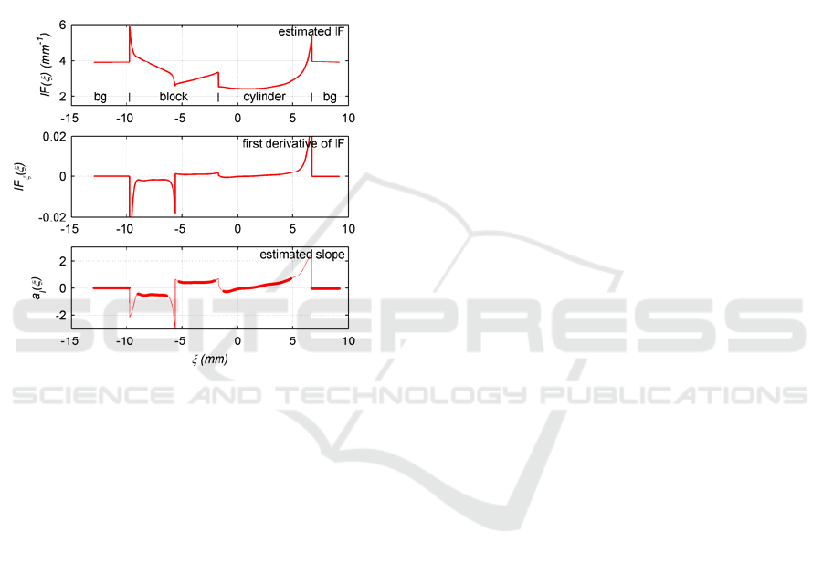
Figure 6: Estimated IF, and its derivative together with the
estimated slope of the profile.
The IF-based estimates are shown as the red
thick lines in Figure 5. The estimated slopes (eq.
(11)) are shown in Figure 6. For the background, and
the two sides of the block, these slopes corresponds
well with the ground truth, i.e.
0, 1, and 1a =− +
l
,
respectively. We used the derivative of
a
l
to decide
whether the corresponding surface patch is planar or
not. Here too, the estimates correspond well to our
expectation, albeit that the accuracy could be
improved. Clearly the IF-method, being dependant
on derivatives, is sensitive to errors in the IF.
6 CONCLUSIONS
We have introduced and demonstrated a new method
for retrieving depth from images of sinusoidally
illuminated scenes. The method is based on the IF
rather than phase. It has the ability to resolve the
ambiguity caused by occlusions in the scene. Phase-
based methods cannot resolve these ambiguities. The
IF method can, but only works for planar surface
patches. We are currently working on extensions to
relieve this condition by, for instance, allowing
quadratic surfaces.
We have assumed an orthographic projection of
the illumination pattern. Currently, we are also
working on a method that uses a perspective
projection model for both the projector and the
camera.
REFERENCES
Salvi, J., Pagès, J., Battle, J., 2004, Pattern codification
strategies in structured light systems. Pattern
Recognition, 37, 827-849.
Srinivasan, V., Liu, H. C., Halioua, M., 1985. Automated
phase-measuring profilometry: a phase mapping
approach. Applied Optics, Vol. 24, No. 2, 185-188.
Takeda, M., Mutoh, K., 1983. Fourier transform
profiliometry for the automatic measurement of 3-D
object shapes. Applied Optics, Vol. 22, No. 24, 3977-
3982.
Su, X., Chen, W., 2001, Fourier transform profilimetry: a
review. Optics and Lasers in Engineering, 35, 263-
284.
Cuevas, F. J., Servin, M., Rodriguez-Vera, R., 1999,
Depth object recovery using radial basis functions.
Optics Communications, 163, 270-277.
Tang, S., Hung, Y. Y., 1990, Fast profilometer for the
automatic measurement of 3-D object shapes. Applied
Optics, Vol. 29, No. 20, 3012-3018.
Tay, C. J., Quan, C., Yang, F. J., He, X.Y., 2004, A new
method for phase extraction from a single fringe
pattern. Optics Communications, 239, 251-258.
Guan, C., Hassebrook, L.G., Lau, D.L., 2003, Composite
structured light pattern for three-dimensional video.
Optics Express, Vol. 11, No. 5, 406-417.
Sansoni, G., Redaelli, E., 2005, A 3D vision system based
on one-shot projection and phase demodulation for
fast profilometry. Measurement Science Technology,
16, 1109-1118.
Hu, Y., Xi., J., Chicharo, J., Yang, Z., 2007, Blind color
isolation for color-channel-based fringe pattern
profilometry using digital projection. J. Opt. Soc. Am
A, Vol. 24, No. 8, 2372-2382.
Boashash, B., 1992, Estimating and Interpreting The
Instantaneous Frequency of a Signal – Part 1:
Fundamentals. Proceedings of the IEEE, Vol. 80, No.
4, 520-538.
Boashash, B., 1992, Estimating and Interpreting The
Instantaneous Frequency of a Signal – Part 2:
Algorithms and Applications. Proceedings of the
IEEE, Vol. 80, No. 4, 540-568.
VISAPP 2009 - International Conference on Computer Vision Theory and Applications
428
