
INERTIAL SENSOR BASED IDENTIFICATION OF
HUMAN MOVEMENTS
Ivo Stancic
1
, Josip Music
1
, Ana Kuzmanic Skelin
1
, Tea Marasovic
1
, Norberto Salgado
2
Tamara Supuk
1
and Vlasta Zanchi
1
1
Faculty of Electrical engineering, Mechanical Engineering and Naval Architecture – FESB
University of Split, Rudjera Boskovica bb, Split, Croatia
2
Department of Electronic, Telecommunications and Informatics, University of Aveiro, Aveiro, Portugal
Keywords: Inertial sensors, Head movement, Standing up movement, Kalman filtering, Spine load during sitting and
standing.
Abstract: The scope of this paper is the presentation of experiments which involve measurements and identification of
human movements by using the inertial sensors. We describe the purpose, design and obtained results of
two experiments, as well as our future plans which include the exploration of the forces acting at spine
segments by measurements with inertial sensors. The first experiment implemented the method for
measuring the range of motion (RoM) of head in transverse plane (Kuzmanic, 2007). It was done in the
Laboratory of Biomechanics and Automatic Control – LaBACS, University of Split. In the second
experiment we analyzed the standing – up movement and we used the robot assistive device for the support
of human while performing the standing – up task. Measurements for purposes of this experiment were done
in the Laboratory of Biomedical Engineering and Robotics, University of Ljubljana. We have proposed the
new method which uses the Extended Kalman filtering for combining the data acquired from inertial sensor
measurements of standing – up movement with data from the dynamic human body model (Music, 2008).
Our plans regarding the next experiment are focused on the identification of the spinal load during sitting
and standing, by using the inertial sensors measurement system.
1 MEASUREMENT OF THE
HEAD’S RANGE OF MOTION
The measurement of range of motion (RoM) and
static posture of the head gives important physical
parameters for clinical assessment and diagnosis
related to cervical spine functions. In literature, this
movement is referred as a cervical range of motion.
The detection of an abnormal RoM or asymmetrical
patterns is an essential for preventing cervical
dysfunction (McAviney, 2005; Wu, 2007).
One of our aims was to investigate the feasibility of
the use of inertial sensors in routine clinical
assessments. Therefore, our goal was to design the
system based on inertial sensors and to propose the
method for measuring the range of motion (RoM) of
head in transverse plane. The measurement was
performed using single inertial measurement unit
MTx XSens sensor (XSens Motion Technologies,
Netherlands), Fig. 1. Specialized software for sensor
data acquisition, with high visualization abilities has
been developed in LaBACAS. MTx XSens sensor
can provide useful, noninvasive measurement of
head motion in three cardinal planes for the fast
evaluation of disturbances related to head/neck
problems and cervical dysfunctions. The advantage
of the proposed method over standard methods is the
ability to measure unilateral RoM of the head. This
technique overcomes the limits of ‘gold standard’
measurement devices by estimating the neutral
position, which is assumed to be a nontrivial problem
in standard RoM measurement. In addition, a
proposal for use of sensor for visual feedback RoM
assessment is presented. LaBACS MTx Software
was developed by in-house, to control the operation
of the inertial measurement unit (IMU), acquire the
data and display them in the real time. Program was
developed under Microsoft Visual Studio 2005, using
MFC (Microsoft Foundation Class). Fig. 2. shows a
frame of running software. Measurement was done
on 6 subjects without any known symptoms of
300
Stancic I., Music J., Kuzmanic Skelin A., Marasovic T., Salgado N., Supuk T. and Zanchi V. (2009).
INERTIAL SENSOR BASED IDENTIFICATION OF HUMAN MOVEMENTS.
In Proceedings of the International Conference on Biomedical Electronics and Devices, pages 300-303
DOI: 10.5220/0001777403000303
Copyright
c
SciTePress
cervical dysfunction. Five repetitions of movements
were analyzed and averaged for each subject in order
to eliminate the variability during movement
recording. In accordance with standard, total RoM is
calculated by subtraction of maximal and minimal
angle, or by summation of left and right RoM,
assuming that the neutral position angle is known.
During the measurement neutral position is identified
statistically, over time interval of five repetitions of
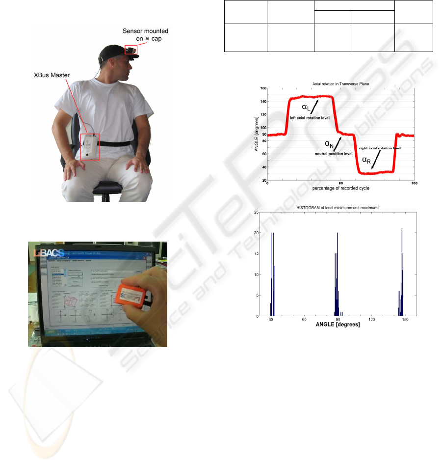
cyclic RoM movement, Fig. 3 b).
Figure 1: Measurement setup: Subject with sensor
mounted on a cap.
Figure 2: User interface of LaBACS MTx Software.
1.1 Results of the First Experiment
The results of the measurement on 6 asymptomatic
subjects are given in Table 1. Resulting angles of
each group are described in terms of mean RoM
± standard deviation [
o
], for the movement on the
left (LRoM) and right side (RRoM). The results of
the present study demonstrate similar ranges of
motion as found in literature (Dvir, 2000), although
the existing results are obtained with different
instrumentation. Measurement of individual neutral
position has a standard deviation ranging from
minimally ±1.12
o
to maximally ±3.36
o
. These results
imply that the subjects are able to return the head to a
self-defined neutral position. Therefore, the
measurement method of head motion based on
inertial sensors is valid for current application of
RoM in transverse plane and is suitable for
measurement of head neutral position, as well.
Table 1: RoM results for 6 asymptomatic subjects.
left side:
LRoM
right side:
RRoM
RoM (total) LRoM/
RRoM
1) 2)
73.02
0
± 7.61
0
74.34
0
± 9.44
0
147.28
0
± 15.51
o
147.36
0
± 15.54
o
1.022
0
± 0.096
0
1) α
L
– α
R
where α
L
is maximal and α
R
is minimal head
angle; 2) LRoM + RRoM
a)
b)
Figure 3: a) Recorded angles of cyclic movement; b)
Histogram computation of head neutral position and
endpoint angles.
2 KINEMATIC MEASUREMENTS
OF STANDING – UP MOTION
Number of aiding systems has been developed for
the purpose of standing–up support. Recently, robot
assistive devices have been introduced and their
benefits demonstrated. In acquisition systems, the
kinetic and kinematic parameters of the subject are
required for operation of the robot control algorithm.
Kinematic measurements are usually performed with
INERTIAL SENSOR BASED IDENTIFICATION OF HUMAN MOVEMENTS
301
optical motion analysis systems that are unsuitable
for clinical applications. Therefore, introduction of
miniature, low cost inertial sensors (accelerometers
and gyroscopes) as a body mounted sensors, has
shown to be promising.
We propose a new approach in which the
Extended Kalman filtering (EKF) technique is used
to fuse data acquired from inertial sensor
measurements with data from the dynamic human
body model (Music, 2008). In this way we believe
that better kinematic measurements in ambulatory
settings are possible. We named the approach Model
Based Inertial Sensing - MoBIS.
The proposed human body model consists of
shank, thigh and HAT (Head-Arms-Trunk)
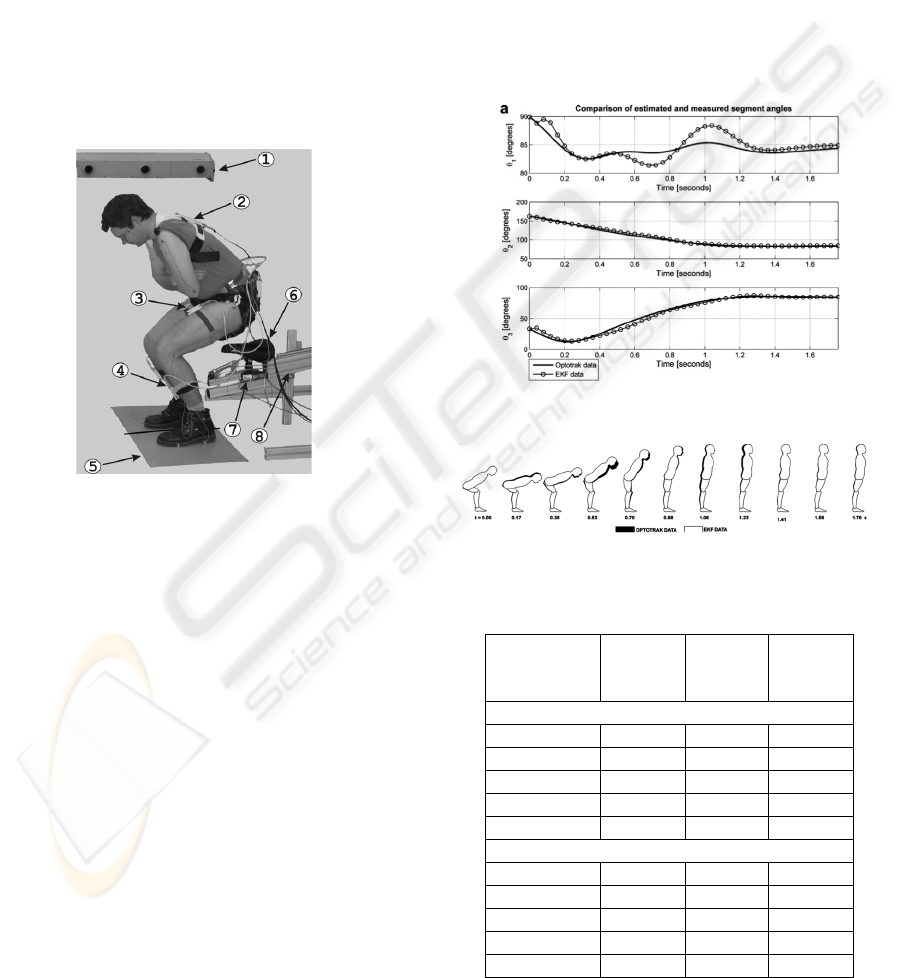
segments, Fig. 4.
Figure 4: Measurement setup: (1) linear infrared cameras,
(2) HAT inertial sensing unit, (3) thigh inertial sensing
unit, (4) shank inertial sensing unit, (5) AMTI OR6-6-1
force plate, (6) seat, (7) JR3 40E15 force sensor, (8)
standing-up robot assistive device.
The segments are assumed to be rigid bodies
with their masses contained at center of mass
(CoM). Segment masses, lengths, moments of inertia
and CoM positions are defined using anthropometric
data. Three joints (ankle, knee and hip) are assumed
to be ideal pin joints with no added friction during
rotation. The model is in contact with its
environment only by the distal end of the shank
segment i.e. by subject’s feet. The assumption of
symmetry of sit-to-stand motion in respect to sagittal
plane was adopted in modeling phase. This
assumption enables the measurements to be carried
out only on one side of the body and results
projected on the other side. The symmetry
assumption does introduce certain error.
2.1 Results of the Second Experiment
The method is validated on both simulated and
measured data. The presented results (Figures 5, 6
and Table 2) show that Model Based Inertial
Sensing (MoBIS) in robot assisted standing-up is a
reliable alternative to optical measurements systems
for motion kinematics assessment. To improve
method performance in terms of accuracy and
reliability, further development (e.g. extensive
testing on a group of healthy and impaired subjects,
introduction of adaptive EKF) is suggested (Music,
2008).
Figure 5: Comparison of actual and measured angles.
Figure 6: Comparison of Optotrak and EKF data.
Table 2: Measurement error.
Shank
RMSE
[deg]
Thigh
RMSE
[deg]
HAT
RMSE
[deg]
Normal/self-selected standing up speed
Meas. 01 6.1 4.1 3.8
Meas. 02 2.1 7.8 6.8
Meas. 03 2.4 5.2 6.8
Meas. 04 3.7 3.5 5.9
Average 1 3.6 5.2 5.8
Fast standing up
Meas. 05 1.4 2.5 3.2
Meas. 06 4.8 2.6 4.7
Meas. 07 4.9 2.4 5
Meas. 08 3.9 2.1 5
Average 2 3.8 2.4 4.5
BIODEVICES 2009 - International Conference on Biomedical Electronics and Devices
302
3 DISCUSSION
AND CONCLUSIONS
Results obtained in described experiments show that
inertial sensors can be implemented into different
measurement systems and bio – devices as reliable
and yet inexpensive tool for identification of
versatile human movements. Our future work
regarding the implementation of inertial sensors
includes the identification of the spinal load during
sitting and standing.
3.1 Segmental Spine Load: Model
and Force Analysis
The main idea is to explore forces acting at single
spine segments. All the measurement procedures,
used in the research, will be noninvasive. The
identification of the single spine segment
coordinates will be done using the inertial sensors.
The later stages will also include the analysis and
calculations of corresponding forces, and therefore,
to that end, ground reaction forces will be measured
(Supuk, 2002). Research will be performed in static
and dynamic conditions, on sitting and standing
subject, Figures 7 and 8. Partial differential
equations will provide mathematical support during
the modeling process, keeping in mind that we are
dealing with compartmental system. Configuration
of the spine, that will be identified based on the
results of measurements obtained by five different
sensor outputs, along with the seat reaction forces
will serve as input parameters for the calculations of
forces acting at the diverse points of the spine (33
vertebrae including the five that are fused to form
the sacrum (the others being separated by
intervertebral discs) and the four bones which form
the tailbone.).
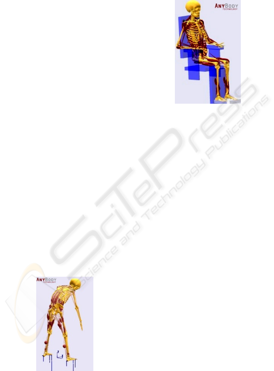
Figure 7: Standing subject spine model.
Figure 8: Musculoskeletal model used to identify spine
configuration of the subject in the seated position.
REFERENCES
Dvir, Z., Prushansky, T., 2000. Reproducibility and
instrument validity of a new ultrasonography-based
system for measuring cervical spine kinematics,
Clinical Biomechanics, Vol. 15, Issue 9, pp. 658-664.
Kuzmanic Skelin, A., Vlak, T., Stancic, I., 2007.
Inertial sensor measurement of head-cervical range of
motion in transverse plane. Proc. of 3rd WSEAS Intl.
Conference on Remote Sensing, Venezia, Italy,
WSEAS Press, pp. 47-51.
McAviney, J., Schulz, D., Bock, R., Harrison, DE.,
Holland, B., 2005. Determining the relationship
between cervical lordosis and neck complaints, J
Manipulative Phisyiol Ther, Vol.28, 2005, pp. 187-
193.
Music, J., Kamnik, R., Munih, M., 2008. Model based
inertial sensing of human body motion kinematics in
sit-to-stand movement, Simulation Modelling Practice
and Theory, Vol. 16, No. 8, pp. 933-944.
Supuk, T., Kuzmanic Skelin, A., Kuzelicki, J., Zanchi, V.,
2002. Estimation of vertical component of ground
reaction force during sit to stand movement: Direct
dynamics approach. In Proceeding of Int.
Electrotehnical and Computer Science Conference
ERK2002, Portoroz, Slovenija, pp. 23-25
Wu, Shyi-Kuen et al, 2007. The feasibility of a video-
based motion analysis system in measuring the
segmental movements between upper and lower
cervical spine, Gait and Posture, Vol.26, 2007, pp.
161-166.
INERTIAL SENSOR BASED IDENTIFICATION OF HUMAN MOVEMENTS
303
