
A TOP DOWN CONSTRUCTION SCHEME FOR IRREGULAR
PYRAMIDS
Romain Goffe
SIC-XLIM, Universit
´
e de Poitiers, CNRS, UMR6172, B
ˆ
atiment SP2MI, F-86962, Futuroscope Chasseneuil, France
Luc Brun
GREYC, ENSICAEN, CNRS, UMR6072, 6 Boulevard du Mar
´
echal Juin, F-14050, Caen, France
Guillaume Damiand
LIRIS, Universit
´
e Lyon, CNRS, UMR5205, Universit
´
e Lyon 1, F-69622, Villeurbanne, France
Keywords:
Segmentation, Irregular pyramid, Topological model, Combinatorial map.
Abstract:
Hierarchical data structures such as irregular pyramids are used by many applications related to image pro-
cessing and segmentation. The construction scheme of such pyramids is bottom-up. Such a scheme forbids the
definition of a level according to more global information defined at upper levels in the hierarchy. Moreover,
the base of the pyramid has to encode any single pixel of the initial image in order to allow the definition of
regions of any shape at higher levels. This last constraint raises major issues of memory usage and processing
costs when irregular pyramids are applied to large images. The objective of this paper is to define a top-down
construction scheme for irregular pyramids. Each level of such a pyramid is encoded by a combinatorial map
associated to an explicit encoding of the geometry and the inclusion relationships of the corresponding parti-
tion. The resulting structure is a stack of finer and finer partitions obtained by successive splitting operations
and is called a top-down pyramid.
1 INTRODUCTION
Quadtrees (Dyer et al., 1980; Jolion and Rosenfeld,
1994) and regular pyramids (Jolion and Rosenfeld,
1994) belong to the first hierarchical data structures
introduced within the computer vision framework.
Both models are based on psycho-visual properties:
focus of attention, for data structure based on recur-
sive split such as quadtrees, and successive process-
ings by neural layers, for bottom-up regular pyramids.
Segmentation using quadtree data structures is based
on a recursive subdivision of a basic shape (e.g. a
square). On the other hand, regular or matrix pyra-
mids are defined as a stack of images with decreasing
resolutions. An entity (square or pixel) defined at a
given level of a pyramid is associated to a connected
set of entities below, called a reduction window (Bis-
ter et al., 1990). Both encoding schemes induce sev-
eral drawbacks on the segmentation process (Bister
et al., 1990).
The irregular pyramid framework introduced by
Meer and Montanvert (Meer, 1989; Montanvert et al.,
1991) partially solves these drawbacks: the stack of
partitions is encoded as a stack of successively re-
duced graphs. Irregular pyramids (Meer, 1989; Mon-
tanvert et al., 1991; Jolion and Montanvert, 1992;
Brun and Kropatsch, 2003) may only be built using a
bottom-up construction scheme. However, a bottom-
up scheme requires an explicit encoding of the base
level image in order to define regions with any shapes
at higher levels. Moreover, in a bottom-up pyramid,
each newly created region has no prior information
about its parents (defined at a later stage). This last
constraint prevents the management of the regions
from depending on the properties of their parents in
the pyramid.
The objective of this paper is the definition of
a top-down hierarchical data structure by extending
the model of two-dimensional topological maps. For
many applications related to image segmentation, it is
163
Goffe R., Brun L. and Damiand G. (2009).
A TOP DOWN CONSTRUCTION SCHEME FOR IRREGULAR PYRAMIDS.
In Proceedings of the Fourth International Conference on Computer Vision Theory and Applications, pages 162-169
DOI: 10.5220/0001782901620169
Copyright
c
SciTePress

critical to minimize memory requirements, mainly for
those processing large images. A top-down approach
rules out the constraint of the explicit storage for the
base: only split regions are kept in memory. Besides,
it offers a perceptual advantage as major features of
an image are discerned first in the pyramid, contrary
to bottom-up models.
We first recall in Section 2, the basics of the dif-
ferent models used to define our top-down irregu-
lar pyramid framework. Then, Section 3 defines our
model of top-down pyramid. We present in Section 4
its construction scheme. Section 5 details the basic
operations used to build a new level of the pyramid.
We finally provide, in Section 6, several experiments
which allow to evaluate the computational times and
memory requirements of our model.
2 RECALLS
2.1 Combinatorial Maps
A combinatorial map encodes all the subdivisions and
incidence relationships of a topological space (Lien-
hardt, 1989). In two dimensions, it is composed of
vertices, edges and faces, respectively defined as cells
of 0, 1 and 2 dimensions and noted i-cells. The bor-
der of an i-cell is a set of ( j < i)-cells. Two i-cells are
said incident if one belongs to the border of the sec-
ond while they are said adjacent if they are both inci-
dent to the same ( j < i)-cell. The degree of an i-cell
is the number of adjacent (i + 1)-cells and a dangling
edge is an edge incident to a degree 1 vertex. Adja-
cency relations are represented by operators noted β
i
and applied to darts, as we will call the abstract basic
elements resulting from a complete decomposition of
the image (Figure 1).
Definition 1 (2-dimensional Combinatorial Map).
A two-dimensional combinatorial map M (or 2-map)
is a triplet M = (D, β
1
, β
2
) where:
(1) D is a finite set of darts;
(2) β
1
is a permutation
1
on D;
(3) β
2
is an involution
2
on D.
Intuitively, a combinatorial map may be under-
stood as a planar graph where relations on edges are
explicitly defined by β
i
operators. Darts allow to dif-
ferentiate the two extremities of an edge and thus, are
1
A permutation is a one to one mapping from S onto S.
2
An involution f is a one to one mapping from S onto S
such that f = f
−1
.
Figure 1: Construction of a 2-map by successive decom-
positions. (A) Original image. (B) Disconnected faces.
(C) Disconnected edges. (D) 2-map: darts are the basic el-
ements represented by arrows, β
1
relations are represented
with arcs and β
2
with bold segments.
assimilated to half-edges. Each dart belongs to a sin-
gle vertex, edge and face of the map. The β
1
permuta-
tion links each dart of a face to the next dart encoun-
tered while turning clockwise around the face (Fig-
ure 1). The β
2
involution links each dart of an edge
to the other dart of the edge which has an opposite
orientation (shared edge between the square and the
triangle in Figure 1). Two darts linked by β
i
are said
i-sewn and two 2-sewn darts belong to two adjacent
faces.
2.2 Topological Maps
Because 2-maps can only represent the topology of
connected objects, we introduce the notion of topo-
logical maps (Brun et al., 2003; Damiand et al., 2004),
an extension of combinatorial maps that uses three
different models to encode: topological relations, ge-
ometrical information and inclusion relationships be-
tween regions.
Topology is based on a 2-map which is minimal
according to its number of cells (Figure 3.A). Al-
though combinatorial maps only represent the topol-
ogy of the space, geometric elements can be added
easily. This association is called embedding. The
geometry relies on the interpixel framework where
an image is considered as a subdivision of a two-
dimensional space in a set of 2-cells, 1-cells and 0-
cells, respectively called pixels, linels, and pointels
(Figure 2). Each border between two regions is thus
defined as a set of linels. Since each dart corresponds
to an oriented boundary, the embedding of a dart de-
fines an order over the set of linels belonging to this
border. The set of linels composing a dart can be rep-
resented explicitly as a sequence of linels or implic-
itly, using a two-dimensional matrix of the size of the
image (Brun et al., 2003; Damiand et al., 2004) (Fig-
ure 3.B).
A region is a set of darts delimited by a β
1
-loop.
Each one has a representative dart which allows to re-
trieve a dart of a given region (e.g. used as a starting
point to find the external border of the region). A set
of adjacent regions is called a connected component
and the union of all the regions create a topologically
VISAPP 2009 - International Conference on Computer Vision Theory and Applications
164
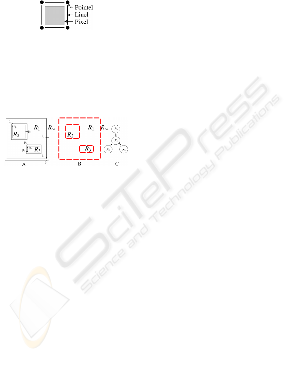
Figure 2: Representation of the interpixel framework: an
image is composed of pixels, linels and pointels.
closed space since we represent the infinite region
3
which encodes the background of the image. A region
included into another one is called a hole and defines
an internal border for the including region. An inclu-
sion tree of regions represents the inclusion relation-
ships of the structure: the father of any region within
the tree is defined as the one which includes it in the
image (Figure 3.C).
Figure 3: The three different models composing a topologi-
cal map. (A) A 2-map representing the topology with darts
and β
i
relations. (B) A geometrical matrix that points out
active linels and pointels. (C) A tree of regions for inclu-
sion relations.
A topological map is a suitable model for image
processing which has been proven complete (repre-
sents both topology and geometry), minimal (retiring
any element would change the topology) and unique
(two topologically equivalent partitions have the same
map) (Damiand et al., 2004). In practice, the min-
imality is required to decrease the number of cells
and minimize memory usage and the completeness
insures that we can encode partitions with regions of
any geometry.
2.3 Pyramids
Simple graph pyramids, first introduced by Meer and
Montanvert (Meer, 1989; Montanvert et al., 1991),
then developed by Jolion (Jolion and Montanvert,
1992) are defined as a stack of simple graphs succes-
sively reduced. Within the segmentation framework,
each graph of such a pyramid encodes a partition. Due
to the limitation of the simple graph data structure,
many issues are encountered when we have to update
these graphs after splitting operations.
3
For visibility reasons, the infinite region may not be
represented in some figures.
Combinatorial pyramids (Brun and Kropatsch,
2003) are built from an initial combinatorial map suc-
cessively reduced by a sequence of contractions and
removal operations. These operations are ruled by
a contraction kernel (forest of the initial combinato-
rial map) and a removal kernel (forest of the dual
combinatorial map). These structures are bottom-up
and the initial combinatorial map (the base) is the
most detailed level: the embedding of each dart of
the base corresponds to a linel. Therefore, the recep-
tive field of any dart may be retrieved from its recep-
tive field and the embedding of the darts defined at
the base (Brun and Kropatsch, 2003). Besides, using
forests avoids disjunctions of connected components
when performing merging operations: two connected
components are linked by a bridge if one is included
into the other (Brun and Kropatsch, 2006). The model
of bottom-up combinatorial pyramid has been gen-
eralized to encode all n-dimensional, orientable or
not and with or without boundary subdivisions (Lien-
hardt, 1989; Simon et al., 2006).
Contrary to bottom-up methods, based on an ex-
plicit encoding of the base of the pyramid, a top-down
approach allows to encode only the upper levels, re-
sulting in a major memory reduction. Moreover, the
focus of attention, encoded by the top-down scheme,
can adapt the segmentation of each region according
to the features of its parents (e.g. with medical im-
ages, the segmentation of cells in a tissue depends on
the tissue itself). Within a top-down scheme, we have
to give up on bridges to represent inclusion relation-
ships. Indeed, the management of the additional con-
nections encoded by the bridges during splitting op-
erations may induce cumbersome computations. For
example, the insertion of an edge at the two endpoints
of a bridge may create an artificial face which has to
be detected and removed. This is why bridges are re-
placed by the use of inclusion tree of regions. More-
over, since the top-down construction scheme avoids
an explicit encoding of the base, the geometry of the
pyramid’s partitions cannot be implicitely encoded at
the base level. The borders of the partition have thus
to be explicitely encoded. These last arguments jus-
tify the use of topological maps as the basis of our
top-down model.
3 MODEL FOR TOP-DOWN
PYRAMIDS
Each level of our top-down pyramid model is encoded
by a topological map, defined by: a 2-map for the
topology, an encoding for the geometrical embedding
of darts and a tree of regions for inclusion relation-
A TOP DOWN CONSTRUCTION SCHEME FOR IRREGULAR PYRAMIDS
165
ships.
Definition 2 (Top-down Topological Pyramid).
Let (n, m, k) ∈ N
3
. A top-down pyramid P is defined
by P = {G
k
} where, ∀k, 0 ≤ k ≤ m:
(1) G
k
= (D
k
, β
k
1
, β
k
2
) is a topological map;
(2) G
k+1
is deduced from G
k
by performing splitting
operations.
Since any level of the top-down pyramid results
from splitting operations (2), every region of G
k
has
a descendant in G
k+1
and every region of G
k
has at
most one antecedent in G
k−1
(same for darts). Thus,
the model is a causal structure (Guigues et al., 2006)
and defines a hierarchy of regions.
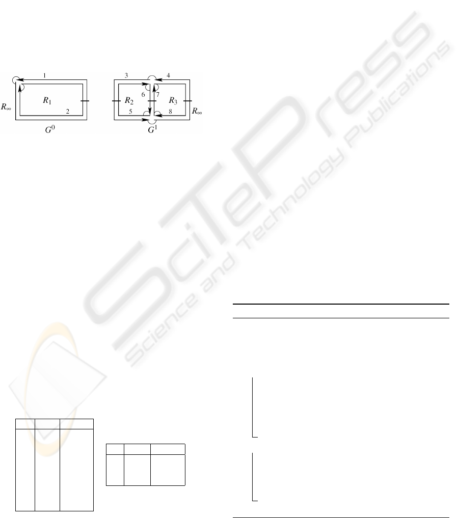
Figure 4: A top-down topological pyramid P, composed of
two levels G
0
and G
1
. Numbers designate darts, β
1
relations
are represented by arcs and β
2
by segments. G
1
is deduced
from G
0
by splitting region R
1
into two regions R
2
and R
3
.
As a hierarchical data structure, the model has to
represent objects and relations through the levels of
the pyramid. So, each dart and region of a map G
k
is
connected to its parent in G
k−1
and its child in G
k+1
(also called ascendant/descendant or up/down). Note
that, although each element (dart or region) has a sin-
gle descendant, there is no loss of information: we
can retrieve for each element the corresponding set of
elements in a lower level. Indeed, the set of children
of a given element is connected so, up and down rela-
tions allow to start from a descendant and to find all
the neighbors which have the same “up”. Neither el-
ements from the top level nor elements newly created
on a level have an antecedent and elements belong-
ing to the base do not have a descendant but several
elements may have the same parent (Table 1).
Table 1: Parent/child relations in pyramid P from Figure 4.
(A) Between darts. (B) Between regions.
D d
up
d
down
1 - 4
2 - 5
3 1 -
4 1 -
5 2 -
6 - -
7 - -
8 2 -
R R
up
R
down
1 - 2
2 1 -
3 1 -
A B
In the following, P denotes a top-down pyramid
composed of m + 1 levels numbered from 0 to m (m
is called the depth of the pyramid). Globally, an ex-
ponent k refers to level k + 1 of the pyramid: G
k
is
the map of level k + 1, D
k
(resp. R
k
) is the set of all
darts (resp. regions) composing level k + 1. An edge
may be noted (d, d
0
) where d and d
0
are the 2-sewn
darts which compose it and R
k
(d) denotes the region
of dart d in level k + 1.
4 CONSTRUCTION SCHEME
This section outlines the global operations construct-
ing a pyramid. The construction is incremental: it
starts from the top and adds new levels one by one at
the bottom. It is composed of three main steps: the
construction of the first (top) level, the creation of a
new level by copying the bottom and the segmenta-
tion of the level that has just been added.
Several methods can be considered to build the
first level of a pyramid but only two are considered
so far. The first method creates a map composed of a
single region enclosing the image and the infinite re-
gion for the outside of the image. The second method
extracts a first topological map from a segmentation
of the image in few regions.
We create a new level by duplicating the last one
of the pyramid. This is why, we build a map equiva-
lent to the bottom (same topology, same geometry and
same tree of regions), link corresponding elements
between the two levels, and finally, add this map at the
bottom of the pyramid (Algorithm 1 and Figure 5.B).
Algorithm 1: Duplication of a level.
Data: A pyramid P of depth m + 1.
Result: A pyramid P of depth m + 2.
Create a new void map G
m+1
;
Copy the geometry of G
m
into G
m+1
;
foreach dart d
up
∈ G
m
do
Create a new dart d
down
in G
m+1
;
Set d
up
as parent of d
down
;
Sew (in G
m+1
) d
down
with the
corresponding down darts of β
1
(d
up
) and
β
2
(d
up
);
foreach region R
up
∈ G
m
do
Create a new region R
down
in G
m+1
;
Set R
up
as parent of R
down
;
Establish inclusions in G
m+1
by setting the
relations of R
down
like those of R
up
;
Set G
m
as parent of G
m+1
;
VISAPP 2009 - International Conference on Computer Vision Theory and Applications
166
The last step of the construction process is the seg-
mentation of the level that has just been duplicated.
This segmentation is based on splitting and merging
operations that transform the level (Algorithm 2).
Algorithm 2: Segmentation of a level.
Data: A level G
k
of a pyramid P.
Result: P with a new segmentation on level G
k
.
foreach region R ∈ G
k
do
if splitting criterion(R) is true then1
Split(R);2
Merge(G
k
, merging criterion);3
Simplify G
k
;4
Compute the new tree of regions;5
Algorithm 2 is composed of four main steps:
• L.1: The splitting criterion indicates if a region
has to be segmented. It is used upstream from the
construction process as an optimization since it
moves uninteresting areas further apart (notion of
focus of attention (Jolion and Rosenfeld, 1994));
• L.2: This step decomposes region R into a set
of square-unit regions, each one enclosing a sin-
gle pixel (Figure 5.C). This operation is detailed
in Section 5.1;
• L.3: The merging criterion determines if two ad-
jacent regions should be merged. In order to pre-
serve the causality property, we restrict the merg-
ing operation to new regions resulting from the
split of a same region (Figure 5.D). Therefore,
two different regions of a level G
p
will never be
merged in a level G
q
, p < q. This operation is
detailed in Section 5.2;
• L.4: The simplification step removes all remain-
ing 2-degree vertices;
• L.5: Because new regions are created, the tree for
inclusion relations has to be rebuilt. Indeed, it
would be too expensive to keep it up-to-date as
many regions are created from a level to another.
Steps L.4 and L.5 rely on the algorithms defined
for topological maps (Damiand et al., 2004). Figure 5
illustrates a simple example of the building process.
5 BASIC OPERATIONS
5.1 Splitting Operation
As mentioned in Section 4, our splitting step decom-
poses a region into a set of basic regions, each one
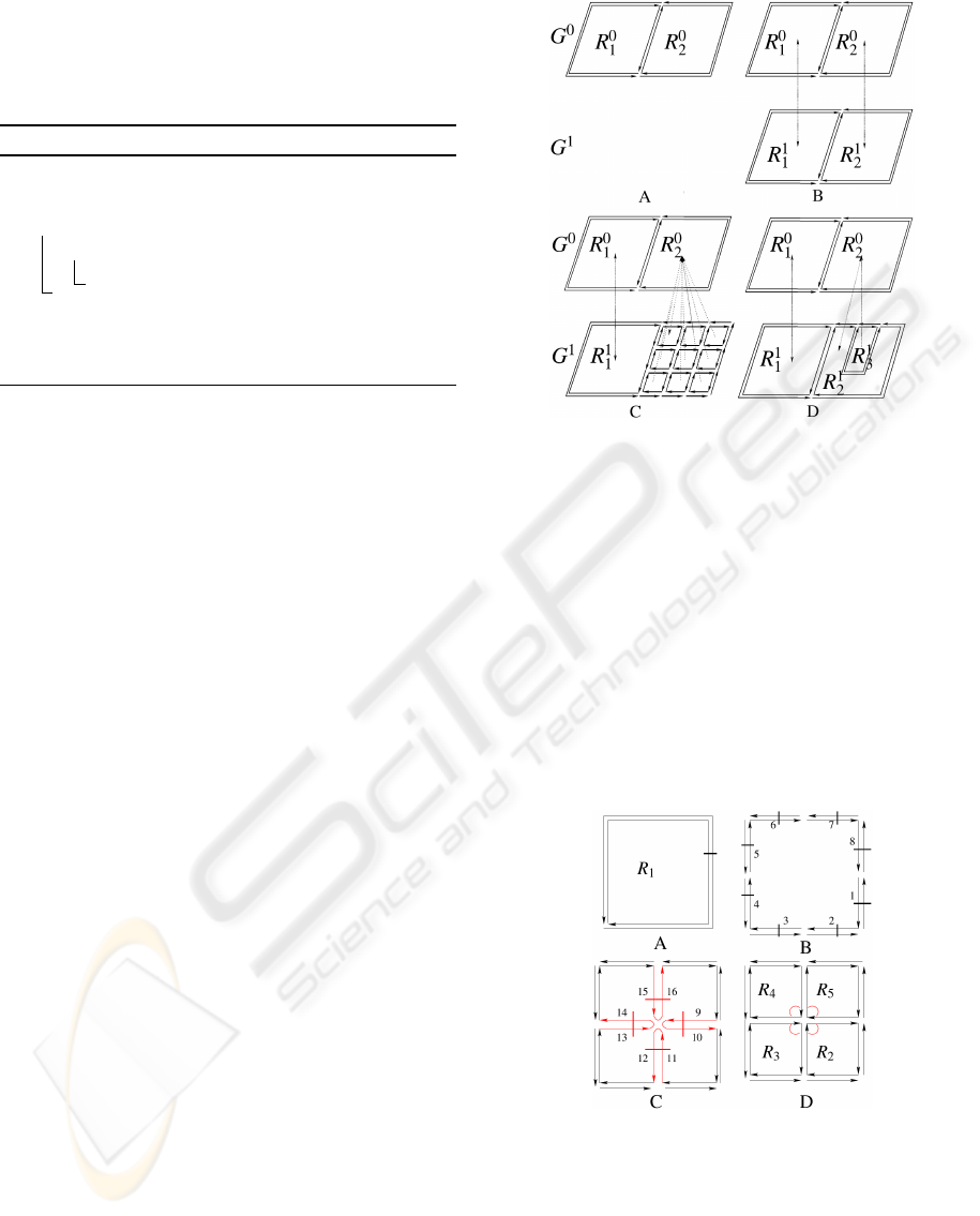
Figure 5: Main steps of the construction process of a top-
down pyramid. (A) Initial step: the pyramid is composed
of a single level G
0
. (B) Duplicate and link: G
1
is a copy
of G
0
and corresponding elements are linked together (for
visibility reasons, dotted lines represent only up/down rela-
tions between regions). (C) Split: R
0
2
is split into a set of
square-unit regions enclosing a single pixel. (D) Merge and
simplify: some of the created regions are merged and draw
R
1
2
and R
1
3
.
enclosing a single pixel. Later, a merging step will
merge these regions: since any couple of adjacent re-
gions may be merged, any subdivision of the initial re-
gion can be encoded. The operation insures that each
created region is both topologically and geometrically
correct (Figure 6).
Figure 6: Decomposition in 4 steps of the splitting process
applied on a region R
1
enclosing 4 pixels. (A) Initial region.
(B) Splitting edges: darts 1 to 8 are stored into list (external
border of R
1
). (C) Insertion of 4 dangling edges while test-
ing darts 1, 3, 5 and 7. (D) Sewing correctly dangling edges
while testing darts 9 and 13.
Assuming that the region to split is denoted R, Al-
gorithm 3 describes the splitting operation which may
be divided into the following steps:
A TOP DOWN CONSTRUCTION SCHEME FOR IRREGULAR PYRAMIDS
167
Algorithm 3: Splitting region
Data: A region R.
Result: R is split into a set of basic regions
enclosing a single pixel.
Split edges of R into unit edges;1
Create list containing every dart of R;2
while ∃ d ∈ list|d is unmarked do
l ← getLinel(d);3
if l
⊥
is not activated then4
Insert edge(d
i
, d
j
) on d;5
Add(d
i
, d
j
) at the end of list;
else if β
2
(d) = β
1
(d) then
1-sew correctly d and β
2
(d) around the6
pointel p incident to β
2
(d);
Mark(d);
• L.1: All the edges belonging to the borders of R
are split into one-linel long edges to allow further
edge insertions;
• L.2: We create a list which initially contains all
the darts resulting from the previous decomposi-
tion of external and internal borders of the region;
• L.3: We retrieve the geometry associated to the
dart. As all edges have been split, the embedding
of each dart of list is a single linel;
• L.4: The external border of a region is clockwise
oriented. Let us denote by l
d
and l
⊥
d
, the oriented
linels encoding respectively the embedding of the
dart d and the next linel encountered after l
d
when
turning counter-clockwise around the pointel as-
sociated to d (e.g. in Figure 6, l
⊥
2
= l
1
). Since
the β
1
permutation connects two consecutive darts
in a clockwise orientation around a face, only l
⊥
d
needs to be considered at this stage. If other darts
remain around the vertex incident to β
2
(d), they
will be considered during further iterations.
• L.5: Actually, an edge insertion on a dart d con-
sists in adding two one-linel long darts d
i
and d
j
(whose embedding is perpendicular to l
d
) on the
pointel p incident to d. Two configurations may
happen as described in Figure 7;
• L.6: In order to sew the 2 darts of the dangling
edge e = (d, β
2
(d)), we geometrically look for
edges perpendicular to e as illustrated in Figure 8.
This operation 1-sew the two darts according to its
number (one or two) of perpendicular edges. At
least one perpendicular edge exists (inserted dur-
ing the previous iteration when processing β
2
(d)).
If four edges are incident to p, processing e will
sew two edges around p and the two others will
be sewn in a further iteration (Figure 6).
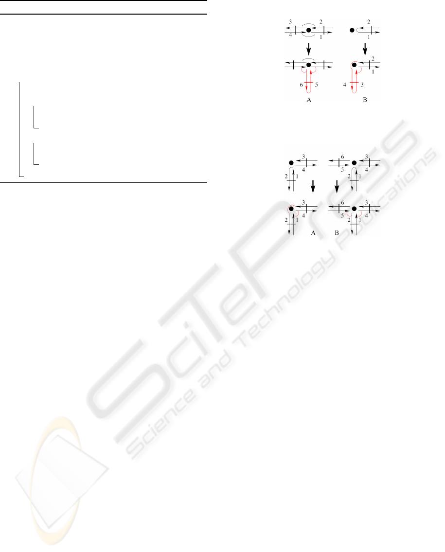
Figure 7: Insertion of a dangling edge on dart 1. (A) In-
sertion of edge (5, 6) on a degree 2 vertex. (B) Insertion of
edge (3, 4) on a degree 1 vertex.
Figure 8: 1-sewing operations when processing dangling
edge (1, 2). (A) One perpendicular edge: 1-sew (1, 4) and
(3, 2). (B) Two perpendicular edges: 1-sew (1, 4) and (5, 2).
This process ensures that each linel within the ini-
tial region is added. Moreover, no dangling edges re-
main: the initial region is initially minimal (i.e. with-
out dangling edges) and if one is inserted, it is added
to the list and then processed and correctly sewn.
Consequently, the splitting operation produces a set
of square-unit regions corresponding to the initial re-
gion.
5.2 Merging Operation
Once the splitting process is done, we need to tra-
verse all the created square-unit regions to segment
the level according to our merging criterion. Actually,
the merging operation is a global process which oper-
ates on a list of darts corresponding to the edges that
were inserted by the splitting operation. This solu-
tion was selected for optimization matter as it avoids a
complete traversal of all the regions. Each edge con-
tained in this list is incident to a couple of adjacent
regions (R, R
0
).
Two configurations may be encountered: simple
or multi adjacency. In the first case, the edge is re-
moved if the merging criterion is satisfied for (R, R
0
)
(Figure 9.A). In case of multi-adjacency, R and R
0
share several edges. If the merging criterion deter-
mines that (R, R
0
) must be merged, all the shared
edges have to be removed (Figure 9.B). Algorithm 4
details the whole process:
VISAPP 2009 - International Conference on Computer Vision Theory and Applications
168
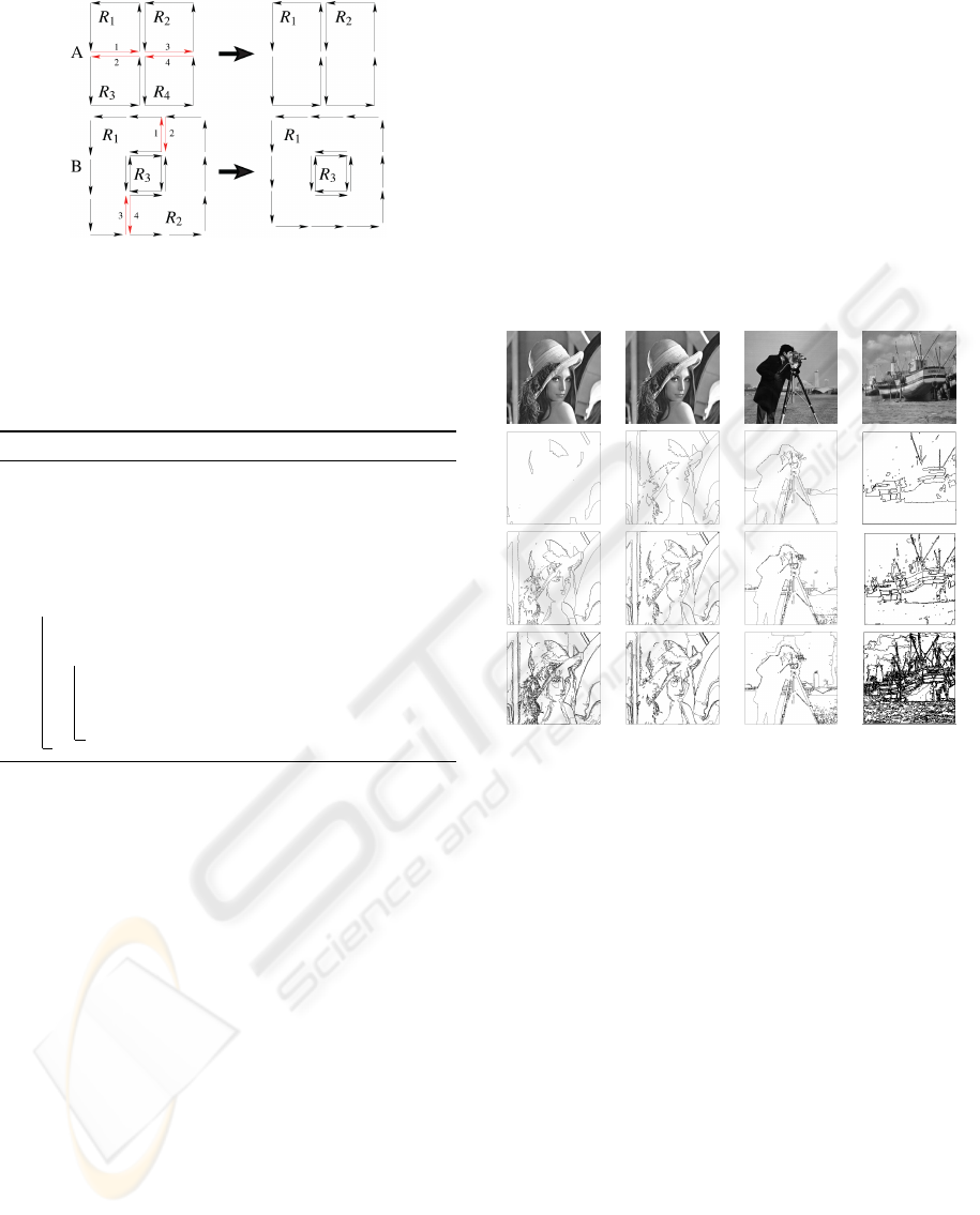
Figure 9: Configurations encountered during the merging
operation between two adjacent regions. (A) Simple ad-
jacency between (R
1
, R
3
) and (R
2
, R
4
): the corresponding
edges (1, 2) and (3, 4) are removed if the merging criterion
is verified. (B) Multi-adjacency between (R
1
, R
2
): if (1, 2)
has been removed, (3, 4) is removed independently of the
merging criterion.
Algorithm 4: Merging operation.
Data: A list of darts corresponding to all the1
edges inserted on G
k
during splitting
operation.
Result: G
k
segmented according to merging
criterion.
foreach dart d ∈ list do
if R(d) = R(β
2
(d)) or merging2
criterion(R(d), R(β
2
(d)))is true then
Turn off getLinel(d) (geometry);3
Relabel the darts of R(β
2
(d));4
Remove d and β
2
(d) (topology);5
• L.1: This list allows to traverse the regions created
by the splitting operation instead of traversing the
whole map. Note that we only need to store one
dart d per edge (the second one is β
2
(d));
• L.2: The first condition aims to detect cases of
multi-adjacency. The merging criterion is a test
between two adjacent regions along the current
edge (i.e. (d, β
2
(d)));
• L.3: Let the geometry know that the linel is not
active any more;
• L.4: This step updates the darts previously com-
posing R(β
2
(d)) as now belonging to R(d);
• L.5: Removal of the two darts, according to the
method in (Damiand and Lienhardt, 2003).
The only constraint applied to the splitting and
merging operations is to preserve the causality of the
structure: merging is thus restricted to the basic re-
gions generated by the split of a same region. There-
fore, within these regions, our merging operation is
unrestricted and may group into a single region, any
connected set of pixels. Any partition of the initial
region may thus be encoded by our split and merge
process. Contrary to quadtrees, our splitting opera-
tion is independent of any geometrical constraint.
6 RESULTS AND ANALYSIS
This top-down model has been implemented in C++
and results have been computed on a personal com-
puter with a CPU AMDX2 3800+ (2GHz) and 1Gb
of RAM on a Linux system.
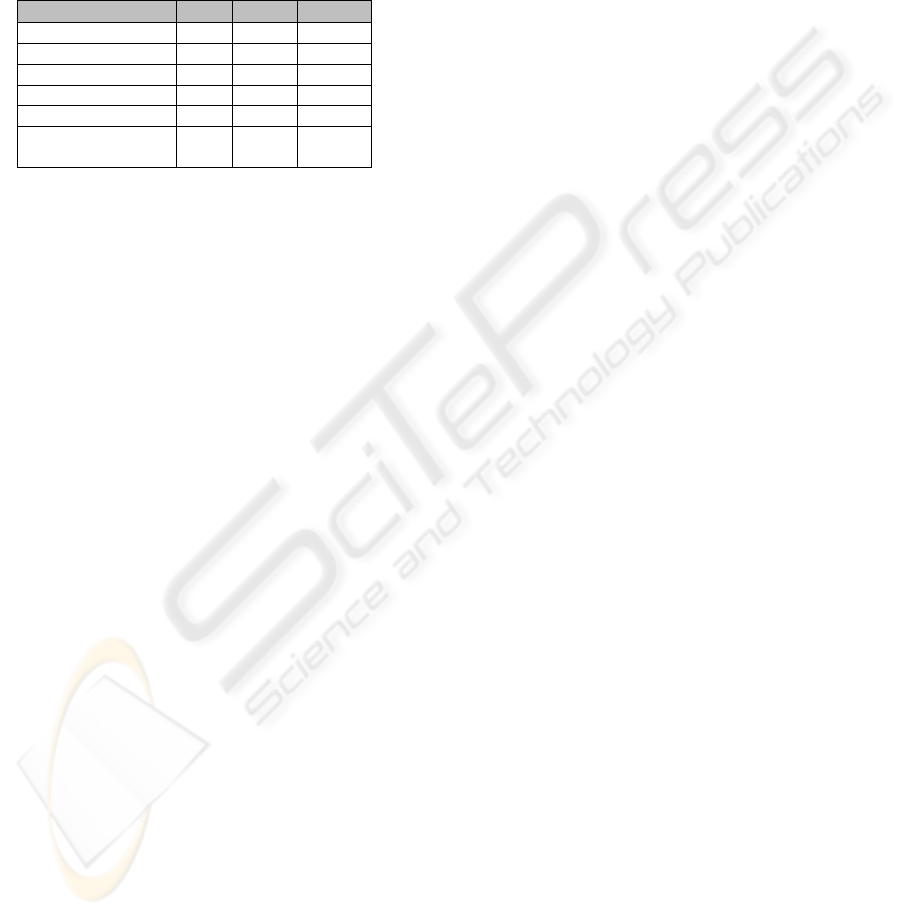
A B C D
Figure 10: Visualization of the top-down construction pro-
cess: first row is the original image followed by levels G
1
,
G
2
and G
3
(G
0
is a single region). Segmentations are based
on user-defined thresholds (A,D) or rely on the standard de-
viation of the parent region (B,C).
The splitting and merging criteria used to obtain
the different segmentations in Figure 10 are defined as
follow: let (R, R
0
) a couple of adjacent regions, M, m
and A denoting the maximum, minimum and average
gray level of R. The symbol tr denotes the threshold
used by the merging criterion.
In Figure 10.A and D, the merging criterion is a
comparison between the average gray levels of two
adjacent regions: (R, R
0
) is merged if |A − A
0
| < tr. In
Figure 10.B and C, tr is proportional to the standard
deviation of the parent region of (R, R
0
): the more ho-
mogeneous a parent region is, the more our segmen-
tation algorithm will search for fine details within its
sons.
The splitting criterion avoids regions with less
than ≤ 10 pixels and those which are going to be
“completely” merged: R is split if M − m > tr. In
Figure 10.A and D, the values of tr are respectively
A TOP DOWN CONSTRUCTION SCHEME FOR IRREGULAR PYRAMIDS
169
set to 80/40/20 and 100/40/10 for the levels G
1
/G
2
/G
3
of the images Lena and Boat. Our splitting and merg-
ing operations are independent of any specific criteria:
more elaborated ones, using geometrical, colorimet-
ric or topological features, may be designed without
modifying our model.
Table 2: Statistics of the top-down construction from the
image of Lena (512*512) in Figure 10.B.
G
1
G
2
G
3
darts 600 7 728 19 090
regions 134 1 624 3 953
total memory (Kb) 306 808 1 604
splitting (s) 2.23 1.42 1.29
merging (s) 0.37 0.27 0.27
total level
3.11 2.05 1.94
construction (s)
Table 2 gives the number of elements, the mem-
ory usage and processing times for each topological
map composing the pyramid of the image Lena. The
number of darts and regions strongly increases from
a level to another as the merging threshold differenti-
ates more regions. It directly impacts the memory size
of the associated topological map. Indeed, the topol-
ogy of a map requires most of the memory, except for
low segmented maps where geometry could require
more. The construction time of a level remains con-
stant because, although more regions are split, they
are smaller in number of pixels.
7 CONCLUSIONS
This paper defines a model of top-down hierarchical
data structure based on topological maps. Topologi-
cal maps are based on three models: a combinatorial
map encoding multiple adjacency of regions, an ex-
plicit encoding of the geometry of the regions border
and an encoding of the inclusion relationships. Such
a model provides a complete description of a partition
and is adapted to splitting operations. Our top-down
pyramid is based on an initial topological map suc-
cessively refined by splitting operations.
This structure is particularly well suited for appli-
cations in segmentation that process large images: a
top-down construction scheme allows to store, at each
step of the algorithm, only the currently split regions
and we avoid the storage of very fine partitions (first
levels of bottom-up irregular pyramids). Besides, can
use global properties of upper levels to refine the seg-
mentation in lower levels and we retrieve the dual re-
lation between quadtrees and matrix pyramids with
top-down and bottom-up approaches.
In our future work, we plan to study different en-
coding of the geometry and of the inclusion relation-
ships of topological maps. We also plan to use other
splitting methods such as (Brun et al., 2003) and to
compare our results with results obtained from other
kinds of pyramids. Finally, we should define segmen-
tation operations which fully exploit the top-down
structure of the pyramid.
REFERENCES
Bister, M., Cornelis, J., and Rosenfeld, A. (1990). A criti-
cal view of pyramid segmentation algorithms. Pattern
Recognition Letter., 11(9):605–617.
Brun, L. and Kropatsch, W. (2003). Combinatorial pyra-
mids. IEEEICIP, 2:33–37.
Brun, L. and Kropatsch, W. (2006). Contains and inside
relationships within combinatorial pyramids. Pattern
Recognition., 39(4):515–526.
Brun, L., Mokhtari, M., and Domenger, J. P. (2003). Incre-
mental modifications on segmented image defined by
discrete maps. Journal of Visual Communication and
Image Representation, 14:251–290.
Damiand, G., Bertrand, Y., and Fiorio, C. (2004). Topolog-
ical model for two-dimensional image representation:
definition and optimal extraction algorithm. Computer
Vision and Image Understanding, 93(2):111–154.
Damiand, G. and Lienhardt, P. (2003). Removal and
contraction for n-dimensional generalized maps. In
DGCI, pages 408–419, Naples, Italy.
Dyer, R., Rosenfeld, A., and Hanan, S. (1980). Region rep-
resentation: Boundary codes from quadtrees. ACM:
Graphics and Image Processing, 23(3):171–179.
Guigues, L., Cocquerez, J. P., and Men, H. (2006). Scale-
sets image analysis. Comput. Vision, 68(3):289–317.
Jolion, J.-M. and Montanvert, A. (1992). The adaptative
pyramid: A framework for 2d image analysis. CVGIP,
55(3):339–348.
Jolion, J.-M. and Rosenfeld, A. (1994). A Pyramid Frame-
work for Early Vision: Multiresolutional Computer
Vision. Kluwer Academic Publishers, Norwell, MA,
USA.
Lienhardt, P. (1989). Subdivision of n-dimensional spaces
and n-dimensional generalized maps. In Sympo-
sium on Computational Geometry, pages 228–236,
Saarbr
¨
ucken, Germany.
Meer, P. (1989). Stochastic image pyramids. CVGIP,
45:269–294.
Montanvert, A., Meer, P., and Rosenfeld, A. (1991). Hi-
erarchical image analysis using irregular tessellations.
IEEETPAMI, 13(4):307–316.
Simon, C., Damiand, G., and Lienhardt, P. (2006). nd gener-
alized map pyramids: definition, representations and
basic operations. Pattern Recognition, 39(4):527–538.
VISAPP 2009 - International Conference on Computer Vision Theory and Applications
170
