
REAL-TIME PIECEWISE PERSPECTIVE PROJECTIONS
Haik Lorenz and J
¨
urgen D
¨
ollner
Hasso-Plattner-Institute, University of Potsdam, Germany
Keywords:
Non-planar projections, Geometry shaders, Geometry amplification, Non-photorealistic rendering.
Abstract:
This paper presents an approach to real-time rendering of non-planar projections with a single center and
straight projection rays. Its goal is to provide optimal and consistent image quality. It operates entirely in
object space to remove the need for image resampling. In contrast to most other object-space approaches, it
does not evaluate non-linear functions on the GPU, but approximates the projection itself by a set of perspective
projection pieces. Within each piece, graphics hardware can provide optimal image quality. The result is a
coherent and crisp rendering. Procedural textures and stylization effects greatly benefit from our method as
they usually rely on screen-space operations. The real-time implementation runs entirely on GPU. It replicates
input primitives on demand and renders them into all relevant projection pieces. The method is independent of
the input mesh density and is not restricted to static meshes. Thus, it is well suited for interactive applications.
We demonstrate it for an analytic and a freely designed projection.
.
1 INTRODUCTION
The pinhole camera model is the most widely used
model for depicting three-dimensional worlds. To-
day’s graphics hardware is tailored to the underlying
projection types: planar perspective or orthographic
projections. Nonetheless, numerous applications in
computer graphics require other, non-pinhole projec-
tion types:
• They are inevitable when using non-planar dis-
plays, such as cylindrical or spherical walls, to
compensate for distortions (Jo et al., 2008).
• Some natural phenomena, such as caustics, reflec-
tions, or refractions off curved surfaces, can be
described by a projection (Wei et al., 2007).
• They can also deliberately introduce distortions
to provide improved perception of a virtual en-
vironment. This includes increased field of view
and lens effects (Popescu and Aliaga, 2006; Brosz
et al., 2007).
• Arts and non-photorealism achieve dramatic ef-
fects using irregular projections (Wood et al.,
1997; Agrawala et al., 2000; Glassner, 2004a;
Glassner, 2004b).
• Images of particular projection types serve as stor-
age for parts of the plenoptic function (Rade-
macher and Bishop, 1998). Most commonly,
these are cubical, spherical, or paraboloidal im-
ages used for rendering reflections or refractions
in real-time (Heidrich and Seidel, 1998; Wan
et al., 2007).
Non-pinhole projections have been discussed exten-
sively in literature, resulting in various camera mod-
els, e.g., (L
¨
offelmann and Gr
¨
oller, 1996; Yu and
McMillan, 2004; Brosz et al., 2007). They cannot be
rendered directly with today’s graphics hardware. In-
stead, ray-tracing is commonly used (L
¨
offelmann and
Gr
¨
oller, 1996). A large body of work exists on imple-
menting ray-tracing on GPU for various phenomena
and scene conditions. (Popov et al., 2007; Wei et al.,
2007) present recent approaches and good surveys of
related methods. Mostly, they use the GPU as power-
ful stream processor instead of as rasterization device
and thus rarely benefit from built-in capabilities such
as anisotropic texture filtering, perspective-correct in-
terpolation, or screen-space derivatives.
This paper focuses on enabling these high qual-
ity rasterization capabilities of current GPUs for non-
pinhole projections. Our approach achieves a signifi-
cantly improved and consistent image quality regard-
less of the input mesh while maintaining real-time
performance (Fig. 1). In particular, we do not use ray
tracing or image resampling, but directly render the
non-pinhole projection. At the same time, we enable
the rasterization hardware to work under perspective
projections exclusively and hence with optimal qual-
147
Lorenz H. and Döllner J. (2009).
REAL-TIME PIECEWISE PERSPECTIVE PROJECTIONS.
In Proceedings of the Fourth International Conference on Computer Graphics Theory and Applications, pages 147-155
DOI: 10.5220/0001786401470155
Copyright
c
SciTePress

Figure 1: A 360
◦
cylindrical view of a city rendered using
a piecewise perspective projection. The city model contains
35,000 triangles and the view uses 160 pieces. At a resolu-
tion of 1600 × 1200, an NVidia 8800GTS achieves 55 fps
with 16x anisotropic texture filtering and 16x antialiasing.
Our technique enables the use of screen-space-dependent
rendering effects such as solid wireframe (Bærentzen et al.,
2006) or pen-and-ink style (Freudenberg et al., 2001).
ity. As a result, procedural textures and stylization
effects can be used instantly regardless of the actual
projection. These properties are achieved by approx-
imating the non-pinhole projection through a set of
connected but disjoint perspective projections. This
construction limits our approach to projections with a
single center and straight projection rays (Single Cen-
ter Of Projection – SCOP).
1.1 Real-time Scop on Gpu
A straightforward and efficient approach to real-
time single-center projections is the implementation
as image-based post-processing effect (Yang et al.,
2005; Trapp and D
¨
ollner, 2008). The rendering con-
sists of two steps: First, a perspective projection is
rendered into an offscreen buffer. Second, this buffer
is used as texture for rendering a deformed mesh.
The offscreen buffer can contain a cube map to en-
able 360
◦
views. This approach is capable of ren-
dering all SCOP effects. It is image-based since the
actual deformation happens after, not during, render-
ing the scene. Its advantages are easy implementation
and good support by graphics hardware. The major
drawback is image quality. The resampling in step
two inevitably introduces blurring artifacts that espe-
cially degrade edges, detailed geometry, procedural
textures, and stylization effects. Today’s hardware ca-
pability of antialiasing through multi-sampling does
not improve image quality substantially as it applies
before resampling.
Object-space approaches do not suffer from im-
age resampling artifacts as they render the image
directly. A simple solution is applying the non-
pinhole projection in the vertex shader (Spindler et al.,
2006). Then a triangle’s vertices are projected cor-
rectly, but the interior and edges are rasterized in-
correctly in a linear fashion. This is acceptable as
long as a triangle’s size on screen and thus the ras-
terization error is limited. Hence, interactive environ-
ments require dynamic refinement. Approaches in-
clude precomputed static levels of detail (Sander and
Mitchell, 2005), progressive meshes (Hoppe, 1996),
adaptive mesh refinement (Boubekeur and Schlick,
2008; Tatarinov, 2008), dynamic mesh refinement
(Lorenz and D
¨
ollner, 2008), or hardware tessellation
units (Tatarchuk, 2007; Casta
˜
no, 2008). They vary
in the distribution of computation between CPU and
GPU. The rendered mesh must be free of T-junctions
to prevent artifacts due to correct vertex location but
incorrect edge rasterization. Even with refinement,
the incorrect rasterization greatly amplifies Z-Buffer
artifacts, such as inaccurate near plane clipping and
interpenetrations of parallel triangles. A solution is
emitting correct depth values in the fragment shader.
This reduces depth test performance and increases
fragment processing overhead due to a disabled early
z-test (Persson, 2007).
A more sophisticated solution is using non-linear
rasterization. Since the rasterizer is a hardwired com-
ponent, (Hou et al., 2006) and (Gascuel et al., 2008)
render a bounding shape for each primitive and use
ray intersection in a fragment shader to compute
the correct fragment and all its attributes under non-
pinhole projections. As a consequence, these meth-
ods cannot benefit from high quality screen-space-
dependent operations built into modern graphics hard-
ware, such as mipmapping, anisotropic filtering, or
screen-space derivatives.
1.2 Piecewise Perspective Projection
Overview
Piecewise perspective projections use an idea pro-
posed in (Hou et al., 2006): simplify a complex pro-
jection by a set of pieces with simpler projections.
The pieces’ projection frusta are connected but dis-
joint with their union approximating the original pro-
jection volume. (Hou et al., 2006) rely on trian-
gle cameras, simple non-pinhole projections, which
makes them capable of rendering multi-perspective
views but prevents them from exploiting hardware
functionality. We restrict the projection pieces to us-
ing perspective projections exclusively, which limits
our technique to SCOP effects.
Key advantage of our construction compared to
all other object-space approaches is the absence of
non-linearities during rasterization. All non-linear as-
pects of the non-pinhole projection are encoded into
the layout of the piecewise approximation. Con-
GRAPP 2009 - International Conference on Computer Graphics Theory and Applications
148

sequently, rasterization and all high quality screen-
space-dependent operations work with optimal qual-
ity within each piece. Similarly, existing shaders, par-
ticularly procedural textures and stylization effects,
can be used instantly. The resulting images do not
exhibit blurring artifacts and capture the non-pinhole
projection regardless of the input mesh and rendering
effect. There is no need for refinement. In addition,
Z-buffer artifacts are not amplified.
The increase in image quality comes at the cost of
increased geometry processing overhead. Each prim-
itive needs to be rendered into each projection piece it
is visible in. Hence, it needs to be processed multiple
times per frame. Depending on the number of pieces
in an approximation, this can result in a substantial
overhead.
The remaining paper is organized as follows: the
next section describes the idea of piecewise perspec-
tive projections in depth and devises a real-time im-
plementation using geometry shaders. Section 3 pro-
vides two example applications. Section 4 provides
experimental results and compares them to alternative
approaches. Section 5 concludes.
2 PIECEWISE PERSPECTIVE
PROJECTION
The key idea of piecewise perspective projections is
the approximation of a non-pinhole projection vol-
ume by a set of connected but disjoint perspective pro-
jection frusta, i.e., projection pieces. Each projection
piece uses a regular perspective projection clipped to
the piece’s boundaries for image formation. Thus,
the rendering encounters no non-linearities and hard-
ware rasterization generates a correct image at opti-
mal quality for each piece. The combination of all
piece images creates an approximation of the desired
non-pinhole projection. The number of pieces defines
the quality of approximation.
For implementing this idea, three challenges need
to be addressed:
1. approximation of the non-pinhole projection with
projection pieces,
2. rendering of a primitive in all projection pieces it
is visible in, and
3. clipping of a primitive’s rendering to the projec-
tion piece’s boundaries.
Approximation. An artifact-free approximation is
only possible for SCOP effects, as other projections
lead to overlapping piece frusta. In general, each pro-
jection piece p uses an individual projection matrix
M
P
(p), such that neighboring pieces produce match-
ing renderings at their shared boundary. Matrix com-
putation depends on the particular projection and hap-
pens once in a preprocessing step. Two typical ap-
proaches are exemplified in Section 3.
Rendering. A simple implementation renders the
whole model for each projection piece with the re-
spective projection matrix and clipping in effect. Ren-
dering should use additional culling to account for a
projection piece’s small screen area but does not re-
quire any change to shaders or meshes to deal with a
non-pinhole projection.
Clipping. Clipping can rely on viewport clipping
if all pieces are rectangular or on user clip planes
for convex pieces. Since both possibilities are per-
formed by the rasterization hardware, no explicit clip-
ping needs to be implemented in a shader. The result-
ing piece images are non-overlapping and thus they
can be rendered directly to the framebuffer without
the need for a dedicated composition step.
Our method can reproduce the same projection ef-
fects as the image-based approach of (Yang et al.,
2005). Their intermediate rendering uses a perspec-
tive projection described by a matrix M
P
. The mesh
used for deforming this rendering implicitly defines
an affine transformation M(t) from the source area of
each triangle t to the screen. An equivalent piecewise
perspective projection can be constructed by clipping
a perspective projection M(t) ∗ M
P
to the deformed
triangle’s boundaries for all triangles t.
The simple implementation mentioned above suf-
fers from increased CPU load due to additional
culling and a large number of draw calls. At the same
time, GPU efficiency is reduced as each draw call ren-
ders to a small screen portion only. Thus, rendering
becomes CPU-bound and real-time performance is
limited to projection approximations with very small
piece counts.
2.1 Real-time Implementation
Our real-time implementation reverses the rendering
approach to make it GPU-friendly. Instead of deter-
mining all primitives for a projection piece, we deter-
mine all relevant, i.e., covered, pieces for a primitive.
We can then render the final image in a single draw
call by replicating each primitive to all its relevant
pieces. Texture buffers allow for changing the pro-
jection matrix within this draw call. User clip planes
cannot be updated that way. The alternative is to de-
fine a standard clip space with fixed clip planes and
provide a transformation from camera space to clip
space for each projection piece.
REAL-TIME PIECEWISE PERSPECTIVE PROJECTIONS
149
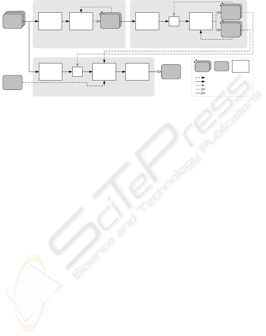
pass 3: indexed rendering
each original primitive is passed as point with all attributes into the rendering pipeline and indexed
by the primitive index; a geometry shader convertes each replication into a rendering primitive
primitive
attributes
vertex shader
geometry shader
(in: points,
out: any primitive)
vertex
cache
fragment shader
GL_POINTS
gl_PrimitiveIDIn
per-primitive
repetition
count
vertex shader
geometry shader
(in: any primitive,
out: points)
per-primitive
replication
count
pass 1: amplification calculation
calculates and writes one replication count per input primitive
gl_PrimitiveIDIn
repetition
numbers
pass 2: primitive index update
uses the existing primitive index as index into replication
counts; each copy of a replication count generates a fraction of the new primitive index
vertex
cache
primitive
index
vertex shader
geometry shader
(in: points,
out: points)
GL_POINTS
gl_PrimitiveIDIn
read as buffer texture (index at tip)
read as attribute / varying
write through transform feedback
write through raster operation
framebuffer
buffer
shader
ping-pong
buffer
read as index
projection &
clip matrices
f(replication number)
replication
numbers (e.g.
0,1,0,0,1,2,…)
primitive
index (e.g.
0,0,1,2,2,2,…)
Figure 2: Primitive replication algorithm overview and data flow. Pass 3 can implement any rendering effect.
Since a primitive can fill the whole screen, the
maximum replication count is the projection piece
count. Hence, a straight forward replication using
geometry shaders, which are currently limited to at
most 128 output vertices, is not possible. In (Lorenz
and D
¨
ollner, 2008) a solution to a similar problem has
been described. They use a fixed three-pass scheme
for per-primitive view-dependent tessellation on GPU
and achieve arbitrary and unbounded geometry am-
plification without CPU intervention. Core of their
scheme is a continuously updated intermediate mesh
of barycentric subtriangles. This transforms the ge-
ometry shader’s output limit from a mesh size limit
to a per-frame growth limit. Since we only require
replicated, not tessellated, primitives, we replace their
intermediate mesh with a primitive index and accom-
panying replication numbers. Both are stored in sep-
arate ping-pong buffers. The primitive index works
similar to a traditional vertex index. The accompa-
nying replication number consecutively numbers all a
single primitive’s occurences in the index. Together,
they enable indexed access to a primitive’s vertex at-
tributes in the vertex shader (e.g., by passing all 3 po-
sitions for a triangle at once) but also allow for distin-
guishing replications of a single primitive in the ge-
ometry shader.
In the following, we provide a brief description
of the rendering process (Fig. 2). For details, re-
fer to (Lorenz and D
¨
ollner, 2008). In the first pass,
all original primitives are processed by a geometry
shader to determine the number of covered projec-
tion pieces. This information is stored in a buffer us-
ing transform feedback. The second pass takes the
previous frame’s primitive index and produces a new
primitive index and matching replication numbers,
such that each primitive is replicated according to the
counts calculated in pass 1. Pass 3 finally renders
all replicated primitives. It uses the primitive index
to fetch all a primitive’s vertex attributes from vertex
buffers and the replication number to select the pro-
jection piece with projection and clip matrix. Addi-
tional vertex, geometry and fragment processing can
implement any effect as if no piecewise perspective
projection was in effect. Thus, existing shaders are
easily incorporated.
This scheme applies to arbitrary “primitive soups”
of any type since no connectivity information or topo-
logical restriction is assumed. Key for rendering is
the determination of covered projection pieces (pass
1) and their enumeration (pass 3). Both depend on the
desired non-pinhole projection. Two aspects need to
be considered. First, while rendering primitives to ir-
relevant pieces does not influence image quality, it de-
grades performance since additional replications are
created and processed only to become clipped again.
Thus, the determination is not required to be exact,
but should be a good estimation. Second, given a
primitive and its replication number, the target pro-
jection piece needs to be identified in O(1) time in a
shader (function f () in Fig. 2). The mapping can be
supported by additional information generated in pass
1. In the following, we present two approaches.
3 APPLICATIONS
Our real-time implementation involves two appli-
cation-dependent parts: projection piece definition
and coverage determination/enumeration. We demon-
strate the use for two typical applications: a horizon-
tal cylindrical projection, which can be described an-
alytically, and texture-based view deformation, which
improves the camera texture technique of (Spindler
et al., 2006).
GRAPP 2009 - International Conference on Computer Graphics Theory and Applications
150
3.1 Cylindrical Projection
A horizontal cylindrical projection uses a perspective
projection in the vertical direction but a non-planar
projection horizontally. Thus, it suffices to limit the
horizontal edge length to control an approximation’s
quality. The piecewise perspective projection then
splits the curved projection volume into narrow rect-
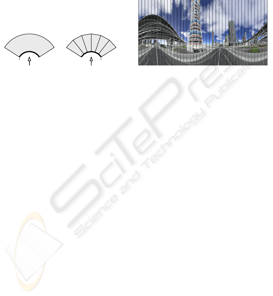
angular slices. Figure 3 sketches this setting.
cylindrical
projection volume
piecewise perspective
approximation
projection surface
projection planes
Figure 3: Top-down view of the cylindrical projection vol-
ume and its approximation with perspective projections.
Projection piece coverage determination and enu-
meration for rendering is rather simple as a single
primitive normally covers a consecutive range of pro-
jection pieces. It suffices to find the leftmost and
rightmost point of the primitive’s projection and ren-
der it to all pieces in between. A special case oc-
curs when cylinder axis and primitive intersect. In
that case, the primitive is potentially visible in all pro-
jection pieces. Finally, wrap-arounds require special
care. In the end, pass 1 outputs both the start piece
index (which can be to the right of the end index)
and piece count. Pass 3 uses a primitive’s replication
number plus the start index modulo n – the number of
projection pieces – as target projection piece.
The projection matrix M of a piece p can be de-
scribed by a series of transformations:
M(p) = M
tx
(p) ∗ M
sx
∗ M
P
∗ M
ry
(p) (1)
M
ry
rotates the center axis of a projection piece about
the y axis onto the negative z axis. M
P
is a perspective
projection matrix with a horizontal field of view ϕ
p
=
ϕ
c
/n, where ϕ
c
denotes the cylindrical field of view.
M
sx
scales the standard postprojective space to fit the
piece’s width on the screen. M
tx
finally moves the
piece’s projection from the screen center to its actual
location on screen.
Clipping requires a standard clip space to enable
fixed clip planes. The following transformation leads
to such a space:
M
clip
(p) = M
s
(M
P
11
;M
P
22
;1) ∗ M
ry
(p) (2)
M
s
is a scaling operation that uses the first (M
P
11
)
and second (M
P
22
) value from the projection matrix’s
diagonal. The complete transformation effectively
transforms into the normalized space used for per-
spective division. The corresponding four clip planes
define an infinite pyramid with the tip being located in
the origin and the opening pointing down the negative
z axis with an opening angle of 90
◦
both vertically
and horizontally.
Figure 4: Rendering of a object-space 360
◦
cylindrical pro-
jection with overlayed wireframe. Piece borders are marked
with black lines.
Fig. 4 depicts a sample image with highlighted
piece boundaries and primitive edges. For clarity, it
uses only 40 pieces. Experiments show, that pieces
of width 10-20 pixels provide a good approximation.
The average replication count is less than 2, while the
maximum replication is the total piece count n.
3.2 Texture-based View Deformation
View deformation (Trapp and D
¨
ollner, 2008) uses one
or more standard perspective views (e.g. a cube map)
and distorts them to create the final image. The distor-
tion is either analytical, such as a paraboloid mapping,
or freely defined, such as camera textures (Spindler
et al., 2006). Both approaches use a rectangular two-
dimensional grid in the perspective view(s) and map
it to a deformed mesh on the screen. The construc-
tion of a piecewise perspective projection follows the
description in Section 2. In the following, we pro-
vide details for an improved implementation of cam-
era textures. They encode the distortion as offset vec-
tors in a 2D texture (Figure 5). A point’s deformed
projection is found by using its perspective projection
for texture lookup and adding the resulting offset vec-
tor to that perspective projection. In contrast to the
original implementation, ours is independent of mesh
density. Regardless of a primitive’s projected size, all
details of the distortion are captured in the primitive’s
interior.
Piecewise perspective projections require splitting
the rectangular grid into triangles. Even though it is
possible to specify a projective mapping from a two-
dimensional rectangle to an arbitrary quadrangle, it
is not possible to guarantee a matching mapping for
REAL-TIME PIECEWISE PERSPECTIVE PROJECTIONS
151
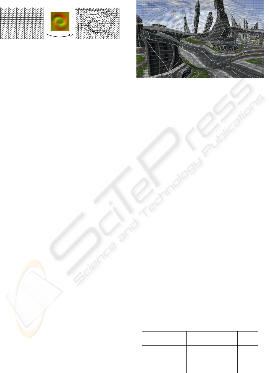
camera
texture
input grid
distorted grid
Figure 5: Projection plane splitting and subsequent distor-
tion using a 16 × 16 pixel camera texture. The model is
rendered directly into the distorted grid.
shared edges. This property would require a bilin-
ear transformation (Heckbert, 1989) current raster-
izers cannot deal with. Splitting the rectangle into
two triangles leads to two affine transformations and
a continuous approximation. Nevertheless, consider-
ing pairs of triangluar projection pieces as one cell is
benefical regarding coverage determination and enu-
meration. It enables operating on a simple rectangular
grid in pass 1. View deformation is irrelevant to pass
1 as it does not change visibility. Pass 2 replicates
primitives for cells. Pass 3 finally emits each primi-
tive twice – once for each triangle in a cell – with the
respective transformation matrices in effect.
A simple solution to determining the coverage of a
primitive is using its bounding box in the undistorted
projection plane. All cells intersected by the bound-
ing box are considered as being covered. Thus, the
output of pass 1 is the position of the lower left cell
c
ll
and width w and height h of the bounding box in
cell units. For efficient storage, all four values use 16-
bit integers and are packed into two 32-bit integers.
Pass 3 can map the replication number r to a cell at
position (c
ll
.x + r mod w ; c
ll
.y +
b
r/w
c
). This two-
dimensional index can be used for lookup in a tex-
ture containing the affine transformation matrices for
both projection pieces in this cell. Since the bounding
box coverage determination is very conservative, we
added culling to pass 3 to discard invisible primitives
before rasterization setup.
The derivation of affine transformation matrices
can be found in (Heckbert, 1989). During rendering,
it is applied subsequent to the original model-view-
projection matrix. Clipping uses a similar approach
as the cylindrical projection. Here, only three clip
planes are in effect, where two neighboring planes of
the pyramid described above are removed and the new
third one is a diagonal. To clip both pieces of one cell
to the same clip planes, one piece’s clip coordinates
are rotated about the z axis by 180
◦
.
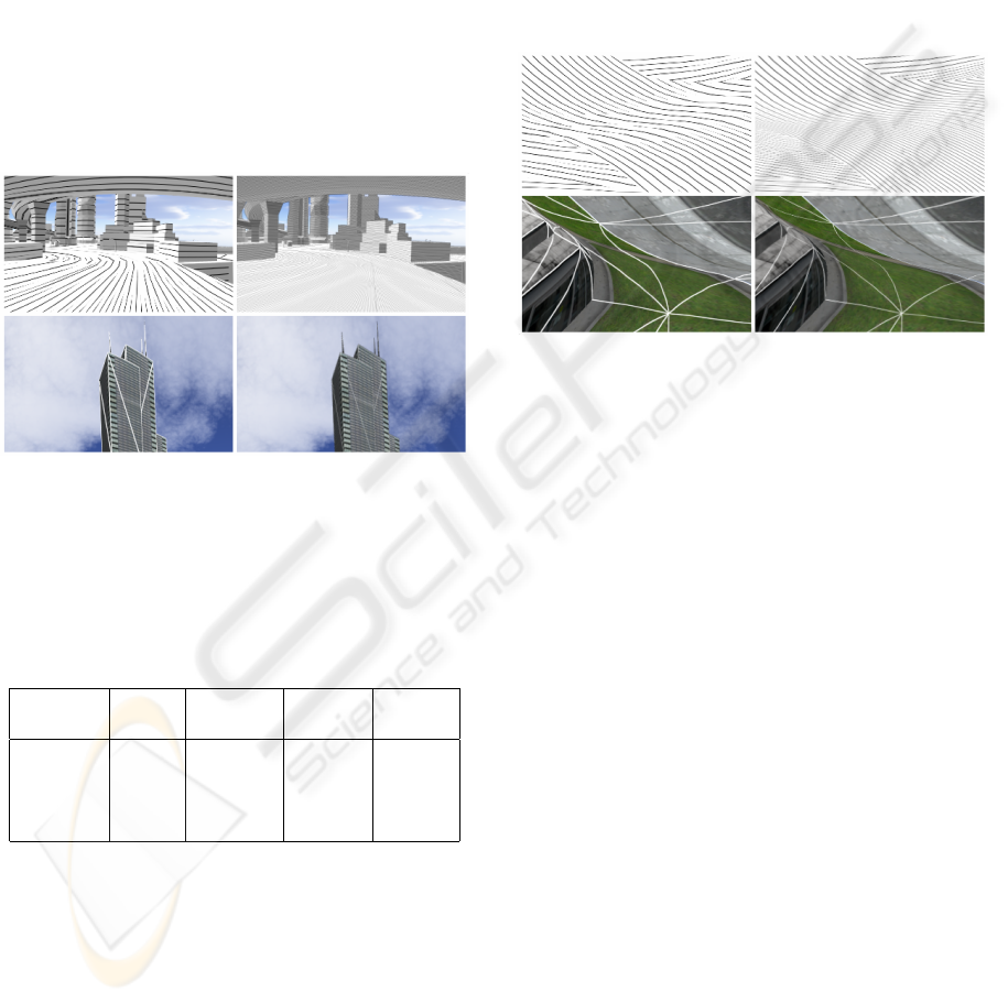
Fig. 6 shows a 128 × 128 camera texture applied
to a view of a city model. A thin black wireframe indi-
cates the triangular projection cells, thick white lines
highlight primitive edges. Even for this moderate tex-
ture size, such a rendering easily requires 1,000,000
Figure 6: Rendering using the camera texture shown in Fig.
5 at a resolution of 128×128. Thin black lines indicate pro-
jection pieces. Thick white lines highlight primitive edges.
triangles while the model only contains about 35,000
primitives. Our implementation of texture-based view
deformation allows for animating the deformation ef-
fect, as this only involves updating the matrices.
4 RESULTS
We compare our object-space technique for both ap-
plications presented in Section 3 to their image-based
implementations. All implementations use native
OpenGL 2.0 with relevant extensions. All measure-
ments have been taken on a desktop PC running Win-
dows XP with an AMD Athlon 64 X2 4200+ proces-
sor, 2GB RAM, and an NVidia GeForce 8800 GTS
with 640 MB RAM. The tests use a path through
the textured city model data shown in Figures 4 and
6. It consists of 35,000 triangles in 14 state groups.
The viewport resolution is 1600 × 1200. In contrast
to (Lorenz and D
¨
ollner, 2008), no latency hiding has
been used since it showed no improvements. Besides
the frame rate, we provide the number of triangles
used for rendering (av. tri count), their replication
ratio to the original triangle count (av. repl. ratio),
and the total size of all vertex buffers used for render-
ing (Vbuf). High quality (HQ) measurements use 16x
anisotropic texture filtering and 16xQ antialiasing.
Table 1: Rendering statistics for the 360
◦
cylindrical cam-
era. Our piecewise perspective projection (PPP) outper-
forms the image-based implementation (IB).
Impl Fps Av. tri Av. repl. Vbuf
count ratio (kB)
IB 41.7 21,151 0.61 1,081
PPP 84.7 67,675 1.96 2,672
IB HQ 33.8 21,151 0.61 1,081
PPP HQ 54.8 67,675 1.96 2,672
GRAPP 2009 - International Conference on Computer Graphics Theory and Applications
152
The image-based implementation of the 360
◦
cylindrical camera uses a dynamic 2048 ×2048 cube-
map that is created in a single pass through lay-
ered rendering. It implements frustum and backface
culling in the geometry shader (Persson, 2007) which
explains the replication count less than 1. The piece-
wise perspective projection uses strips of 10 pixels,
i.e., 160 pieces, for approximation. On average, each
triangle is visible in only two strips. The increased
memory footprint results from the intermediate mesh,
which requires 16 bytes per rendered primitive. In
total, our method outperforms the image-based ap-
proach while providing higher image quality (Fig.
7). Even for smaller cubemaps, the image-based ap-
proach does not overtake ours, but image quality fur-
ther degrades.
Figure 7: Comparision of image quality for cylindrical pro-
jection. Closeups of screen shots for PPP (left) and IB
(right). Top: pen-and-ink style, bottom: depth-dependent
solid wireframe.
Table 2: Rendering statistics for the view deformation with
a 128 × 128 camera texture. While achieving significantly
better image quality, performance can not compete with the
image-based approach.
Impl Fps Av. tri Av. repl. Vbuf
count ratio (kB)
IB 206.2 34,596 1 1,081
PPP 8.4 727,982 21.04 13,858
IB HQ 95.8 34,596 1 1,081
PPP HQ 8.2 727,982 21.04 13,858
For the texture-based view deformation, the
image-based technique uses only a 2D texture, no
cubemap. Therefor, it achieves higher frame rates
than for the cylindrical projection. In contrast, our
method needs to render a significantly higher amount
of triangles, which translates to a severely reduced
speed. Each input triangle spans on average about 21
of the 32,258 projection pieces. While delivering in-
teractive frame rates, the vertex processing overhead
is substantial. The bottleneck is pass 3. Primitive
replication performed in pass 1 and 2 accounts for
only 6% of the total workload. Consequently, a more
aggressive coverage determination than the bounding
box test could significantly improve performance. In
addition, a projection piece size of 20 × 20 pixels suf-
fices for good approximations, i.e., the camera texture
resolution should be adapted to the viewport resolu-
tion. In our example, using a suitable 80 × 60 camera
texture increases the frame rate to 22.1 fps (HQ: 20.9
fps) at an av. tri count of 351,954. Figure 8 shows the
improved image quality.
Figure 8: Comparision of image quality for texture-based
view deformation. Closeups of screen shots for PPP (left)
and IB (right). Top: pen-and-ink style, bottom: depth-
dependent solid wireframe.
5 CONCLUSIONS
This paper has presented a novel object-space ap-
proach to rendering non-pinhole projections with a
single projection center. The piecewise perspective
projection technique removes non-linearities from
rendering by approximating a projection with a set
of perspective projections. The distorted image is
formed directly on screen without intermediate ren-
dering steps. As a result, all image quality opti-
mizations provided by modern graphics hardware that
assume a perspective projection continue to operate
with regular precision. Particularly, antialiasing, pro-
cedural textures, and stylization effects profit from
our technique. It can be implemented on any graph-
ics hardware but requires DirectX10 features for real-
time performance. Core is on-demand replication of
primitives on the GPU using geometry shaders and
transform feedback, such that a primitive is rendered
into only those projection pieces it actually covers.
The technique’s drawback is a high geometry pro-
cessing overhead. Primitive replication itself is rather
efficient. The major bottleneck is vertex processing in
pass 3 since a rendered primitive covers at most one
projection piece. In the example with a 128 × 128
REAL-TIME PIECEWISE PERSPECTIVE PROJECTIONS
153

pixel view deformation texture, up to 1,000,000 tri-
angles are needed for rendering a frame. In the fu-
ture, we seek to improve the performance of pass 3
both by better coverage determination and exploita-
tion of hardware caches during processing of repli-
cated primitives. A second direction of research is
evaluating applicability to other types of projections,
such as slit or pushbroom cameras. The rendering
scheme might also prove useful for other algorithms,
e.g., (Hou et al., 2006). Finally, future graphics
hardware will include an additional tessellation unit
(Casta
˜
no, 2008), which might enable a single-pass
implementation of piecewise perspective projections.
ACKNOWLEDGEMENTS
This work has been funded by the German Federal
Ministry of Education and Research (BMBF) as part
of the InnoProfile research group “3D Geoinforma-
tion” (www.3dgi.de).
REFERENCES
Agrawala, M., Zorin, D., and Munzner, T. (2000). Artistic
multiprojection rendering. In Proc. of the Eurograph-
ics Workshop on Rendering Techniques 2000, pages
125–136. Springer-Verlag.
Bærentzen, A., Nielsen, S. L., Gjøl, M., Larsen, B. D., and
Christensen, N. J. (2006). Single-pass wireframe ren-
dering. In ACM SIGGRAPH 2006 Sketches, page 149.
ACM.
Boubekeur, T. and Schlick, C. (2008). A flexible kernel for
adaptive mesh refinement on GPU. Computer Graph-
ics Forum, 27(1):102–114.
Brosz, J., Samavati, F. F., Sheelagh, M. T. C., and Sousa,
M. C. (2007). Single camera flexible projection. In
Proc. of NPAR ’07, pages 33–42. ACM.
Casta
˜
no, I. (2008). Tesselation of displaced subdivision sur-
faces in DX11. In XNA Gamefest 2008.
Freudenberg, B., Masuch, M., and Strothotte, T. (2001).
Walk-through illustrations: Frame-coherent pen-and-
ink in game engine. In Proc. of Eurographics 2001,
pages 184–191.
Gascuel, J.-D., Holzschuch, N., Fournier, G., and P
´
eroche,
B. (2008). Fast non-linear projections using graphics
hardware. In Symposium on Interactive 3D graphics
and games SI3D ’08, pages 107–114. ACM.
Glassner, A. S. (2004a). Digital cubism. IEEE Computer
Graphics and Applications, 24(3):82–90.
Glassner, A. S. (2004b). Digital cubism, part 2. IEEE Com-
puter Graphics and Applications, 24(4):84–95.
Heckbert, P. S. (1989). Fundamentals of texture mapping
and image warping. Technical report, University of
California at Berkeley, Berkeley, CA, USA.
Heidrich, W. and Seidel, H.-P. (1998). View-independent
environment maps. In HWWS ’98: Proc. of the ACM
SIGGRAPH/EUROGRAPHICS workshop on Graph-
ics hardware, pages 39–45. ACM.
Hoppe, H. (1996). Progressive meshes. In Proc. of SIG-
GRAPH ’96, pages 99–108. ACM.
Hou, X., Wei, L.-Y., Shum, H.-Y., and Guo, B. (2006).
Real-time multi-perspective rendering on graphics
hardware. In EUROGRAPHICS Symposium on Ren-
dering. Blackwell Publishing.
Jo, K., Minamizawa, K., Nii, H., Kawakami, N., and Tachi,
S. (2008). A GPU-based real-time rendering method
for immersive stereoscopic displays. In ACM SIG-
GRAPH 2008 posters, page 1. ACM.
L
¨
offelmann, H. and Gr
¨
oller, E. (1996). Ray tracing with
extended cameras. Journal of Visualization and Com-
puter Animation, 7(4):211–227.
Lorenz, H. and D
¨
ollner, J. (2008). Dynamic mesh refine-
ment on GPU using geometry shaders. In Proc. of the
16th WSCG.
Persson, E. (2007). ATI radeon HD2000 programming
guide. Technical report, AMD, Inc.
Popescu, V. and Aliaga, D. G. (2006). The depth discon-
tinuity occlusion camera. In SI3D, pages 139–143.
ACM.
Popov, S., Gunther, J., Seidel, H.-P., and Slusallek, P.
(2007). Stackless kd-tree traversal for high perfor-
mance gpu ray tracing. Computer Graphics Forum,
26:415–424.
Rademacher, P. and Bishop, G. (1998). Multiple-center-of-
projection images. In SIGGRAPH, pages 199–206.
Sander, P. V. and Mitchell, J. L. (2005). Progressive Buffers:
View-dependent Geometry and Texture for LOD Ren-
dering. In Symposium on Geometry Processing, pages
129–138. Eurographics Association.
Spindler, M., Bubke, M., Germer, T., and Strothotte,
T. (2006). Camera textures. In Proc. of the 4th
GRAPHITE, pages 295–302. ACM.
Tatarchuk, N. (2007). Real-time tessellation on GPU. In
Course 28: Advanced Real-Time Rendering in 3D
Graphics and Games. ACM SIGGRAPH 2007.
Tatarinov, A. (2008). Instanced tessellation in DirectX10.
In GDC ’08: Game Developers’ Conference 2008.
Trapp, M. and D
¨
ollner, J. (2008). A generalization approach
for 3d viewing deformations of single-center projec-
tions. In Proc. of GRAPP 2008, pages 162–170. IN-
STICC Press.
Wan, L., Wong, T.-T., and Leung, C.-S. (2007). Isocube:
Exploiting the cubemap hardware. IEEE Trans. on
Vis. and Comp. Graphics, 13(4):720–731.
Wei, L.-Y., Liu, B., Yang, X., Ma, C., Xu, Y.-Q., and Guo,
B. (2007). Nonlinear beam tracing on a GPU. Tech-
nical report, Microsoft, MSR-TR-2007-168.
GRAPP 2009 - International Conference on Computer Graphics Theory and Applications
154

Wood, D. N., Finkelstein, A., Hughes, J. F., Thayer,
C. E., and Salesin, D. H. (1997). Multiperspective
panoramas for cel animation. In Proc. of ACM SIG-
GRAPH ’97, pages 243–250. ACM Press/Addison-
Wesley Publishing Co.
Yang, Y., Chen, J. X., and Beheshti, M. (2005). Nonlinear
perspective projections and magic lenses: 3d view de-
formation. IEEE Comput. Graph. Appl., 25(1):76–84.
Yu, J. and McMillan, L. (2004). General linear cameras. In
ECCV (2), volume 3022 of Lecture Notes in Computer
Science, pages 14–27. Springer.
REAL-TIME PIECEWISE PERSPECTIVE PROJECTIONS
155
