INTERACTIVE STEREO RENDERING FOR NON-PLANAR
PROJECTIONS OF 3D VIRTUAL ENVIRONMENTS
With a Comparison of Image- and Geometry-based Approaches
Matthias Trapp, Haik Lorenz and J
¨
urgen D
¨
ollner
Hasso-Plattner-Institute, University of Potsdam, Prof.-Dr.-Helmert-Str. 2-3, Potsdam, Germany
Keywords:
Stereoscopic Imaging, Non-planar projections, Real-time rendering.
Abstract:
Stereo rendering, as an additional visual cue for humans, is an important method to increase the immersion
into 3D virtual environments. Stereo pairs synthesized for the left and right eye are displayed in a way that
the human visual system interprets as 3D perception. Stereoscopy is an emerging field in cinematography
and gaming. While generating stereo images is well known for standard projections, the implementation of
stereoscopic viewing for interactive non-planar single-center projections, such as cylindrical and spherical pro-
jections, is still a challenge. This paper presents the results of adapting an existing image-based approach for
generating interactive stereoscopic non-planar projections for polygonal scenes on consumer graphics hard-
ware. In particular, it introduces a rendering technique for generating image-based, non-planar stereo pairs
within a single rendering pass. Further, this paper presents a comparison between the image-based and a
geometry-based approach with respect to selected criteria.
1 INTRODUCTION
Stereoscopy is the phenomenon of simultaneous vi-
sion with two eyes, producing a perception of the rel-
ative distances between objects in space. Stereoscopy
can be created by using a stereo image pair displayed
with active or passive stereo viewing concepts, which
enable the experience of the stereo sensation. This
feature is a requirement for 3D immersive digital en-
vironments. Creating stereo image pairs is straight-
forward for planar projections that can be accelerated
by graphics hardware. The renderer needs to create
an image pair, one image for the left eye and one for
the right eye. Most of todays computer games and
visualization frameworks offer a 3D stereo mode for
standard planar projections.
Enabling interactive stereo rendering for non-
planar projections is not a trivial problem. This is
especially true for rendering on polygonal consumer
graphics hardware without the support of parallel or
distributed systems. The optimal solution for this
problem enfolds the following attributes: It should
enable rendering at interactive frame rates for large-
scale models, such as virtual 3D city models or land-
scapes on current consumer hardware. Further, the
approach should be applicable to multiple variants
of single-center projections, support omni-directional
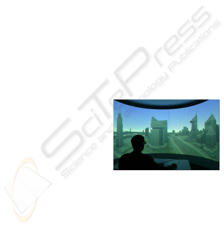
Figure 1: Application of a passive stereo rendering tech-
nique for immersive virtual environments.
stereo, deliver high-quality images, and should be
easy to implement and integrate into existing render-
ing frameworks. Figure 1 shows a passive anaglyph
stereo rendering of a 180
◦
cylindrical projection per-
formed in real-time, displayed on a half-cylindrical
screen.
This paper presents the application of image-
based (IBA) and geometry-based (GBA) approaches
for creating non-planar projections (NPP) to stereo
rendering, and makes to the following contributions
to the reader: It extends an image-based approach for
generating non-planar projection described in (Trapp
199
Trapp M., Lorenz H. and Döllner J. (2009).
INTERACTIVE STEREO RENDERING FOR NON-PLANAR PROJECTIONS OF 3D VIRTUAL ENVIRONMENTS - With a Comparison of Image- and
Geometry-based Approaches.
In Proceedings of the Fourth International Conference on Computer Graphics Theory and Applications, pages 199-204
DOI: 10.5220/0001790701990204
Copyright
c
SciTePress

and D
¨
ollner, 2008) with the functionality of interac-
tive rendering for active and passive stereo viewing.
We present a new rendering technique that renders
theses stereo images within a single scene render-
ing pass. The paper gives explanations for the im-
plementation using modern graphics hardware. We
further present a performance evaluation of the ex-
tended rendering technique as well as a compari-
son between IBA and GBA described in (Lorenz and
D
¨
ollner, 2008) by using different criteria.
This paper is structured as follows. Section 2 gives
an overview of related and previous work concerning
our topic. Section 3 introduces the basic concepts of
stereoscopic rendering and reviews the image-based
and geometry-based approaches for generating non-
planar projections. Section 4 focuses on the imple-
mentation of our rendering technique and presents a
performance evaluation. Section 5 compares IBA and
GBA. Section 6 discusses of the results and concludes
the paper.
2 RELATED & PREVIOUS WORK
Besides approaches for omni-directional non-planar
projections and camera systems (Peleg et al., 2001)
that stitch real-world images to obtain a still stereo
image, we find approaches for stereo rendering on
multi-projector systems (Bimber et al., 2005). This
work reflects non-planar projections for single projec-
tion centers which can be created using image-based
and geometry-based approaches. We focus on the last
two.
Image-based Approaches. These rendering tech-
niques are mainly based on two phases. First, a raster
representation of the virtual scene is created using off-
screen rendering. In the second phase, this represen-
tation is used to create different projections or image-
distortions using image warping in a post processing
step (Yang et al., 2005). In (Trapp and D
¨
ollner, 2008)
a generalization of this approach is described that uses
a cube map texture to represent the virtual environ-
ment and create multiple NPPs and variants of image
distortions.
Geometry-based Approaches. A straight-forward
GBA implementation simply projects all mesh ver-
tices non-planarly and rasterizes the primitives imme-
diately (Spindler et al., 2006). The inadequate linear
interpolation during rasterization requires highly tes-
sellated meshes for artifact-free renderings. Dynamic
mesh tessellation based on instancing (Boubekeur and
Schlick, 2008; Tatarinov, 2008), geometry shaders
(Lorenz and D
¨
ollner, 2008), or hardware tessellation
units (Tatarchuk, 2007) can ensure this property for
arbitrary meshes. An alternative approach is tessellat-
ing the non-planar projection into smaller and simpler
projections. (Hou et al., 2006) describes an approach
for rendering arbitrary projections which is conceptu-
ally based on beam tracing.
3 BASIC CONCEPTS
Regardless of the rendering techniques used for cre-
ating non-planar projections, the creation of stereo-
scopic views comprises the following two basic steps:
1. Generating Stereo Pairs: The NPP for the left
and right images are synthesized by using image-
based or geometry-based rendering techniques.
2. Stereo Rendering: The stereo pairs are combined
into a single frame buffer (passive stereo) or ren-
dered into two frame buffer (active stereo) by us-
ing post-processing compositing passes.
3.1 Image-based Projections
Before we describe how to create stereo renderings
for non-planar projections, we briefly review the ap-
proach described in (Trapp and D
¨
ollner, 2008). This
approach uses a dynamically created cube-map tex-
ture to capture the complete virtual environment that
surrounds the virtual scene camera. The non-planar
projections are derived by applying a projection func-
tion δ
P
that samples the cube map using computed
normal vectors. This functionality is implemented in
a fragment shader program using a post-processing
pass. It is activated when rendering a screen-aligned
quad that covers the whole view port.
This paper adapts and extends the described con-
cept to support stereo rendering. A na
¨
ıve approach
is the creation of two cube maps using two render-
ing passes and then perform stereo rendering by com-
puting two non-planar projections. To avoid unneces-
sary state changes for multi-pass rendering, we pro-
pose a method that creates two cube map textures
within a single rendering pass. This fully hardware-
accelerated technique is described in Section 4. It
integrates into the referenced image-based approach,
and therefore benefits from further functionality such
as generalizations of non-planar projections.
3.2 Geometry-based Projections
Object-space approaches do not rely on resampling of
an intermediate texture to achieve the non-planar pro-
jection effect. They apply the projection directly to
GRAPP 2009 - International Conference on Computer Graphics Theory and Applications
200
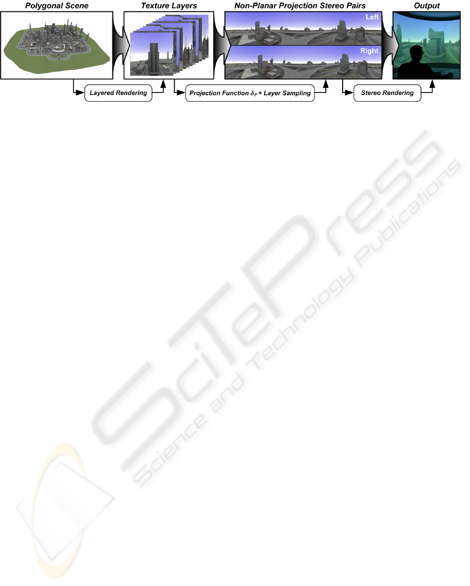
Figure 2: Overview of the implementation concept for image-based stereo rendering for non-planar projections. Layered
rendering is used to create image representations of the input geometry. These images are synthesized into stereo pairs of
non-planar projections which are then viewed in stereo.
mesh vertices and render the final image immediately
using regular rasterization. At this point, we sum-
marize the approach taken by (Lorenz and D
¨
ollner,
2008). They use geometry shaders to generate a view-
dependent tessellation with limited edge length per
primitive. For performance, they rely on an inter-
mediate mesh using barycentric coordinates. Since
geometry shaders are currently not capable of emit-
ting sufficient primitives at once, a three-pass scheme
is used: first, the required tessellation level is deter-
mined per original primitive. Second, the existing
tessellated intermediate mesh is refined to meet the
new tessellation requirements. Third, the intermedi-
ate mesh is converted into a fully attributed mesh, pro-
jected, and rendered to the screen.
To enable stereo rendering, layered rendering can
be used to create both images at once. The third pass
simply emits each primitive twice using separate pro-
jections and directs them into two different layers. A
subsequent compositing pass creates the stereo view.
4 IMPLEMENTATION
Our exemplary implementation is based on OpenGL
(NVIDIA, 2008) and the OpenGL shading language
(Kessenich, 2006). The GBA enables the direct out-
put of the stereo pair using a single scene evaluation
and is not discussed furthermore. This section focuses
on the extension of the IBA to create the raster repre-
sentation within a single scene rendering pass. Fig-
ure 2 shows an overview of our implementation con-
cept. The rendering process for creating stereo pairs
enfolds the following three steps per frame:
1. Update Camera Orientation: The twelve camera
orientations for all cube-map faces are updated us-
ing the parallel camera mode. The off-axis and
toe-in camera modes (Bourke and Morse, 2007)
are not used, since they lead to artifacts or miss-
ing stereo disparity.
2. Create Raster Representations: There are three al-
ternatives for creating raster representation of the
virtual 3D scene. The first uses multi-pass ren-
dering to create two cube-map textures by ren-
dering one pass for each cube map face, i.e.,
twelve passes in total. The second requires one
pass for each cube-map texture by using render-
to-cubemap (RTC), i.e., two passes in total. The
third creates twelve layers, corresponding to each
face of two cube maps textures, within a single
rendering pass. This section focuses on the third
alternative.
3. Apply Projection: The raster representations are
transformed into two non-planar projections (left,
right). This is done in one or two full-screen post-
processing passes using a single frame buffer for
passive stereo rendering or a dual frame buffer for
active hardware stereo rendering.
4.1 Creating Raster Representations
The present generation of raster-based polygonal ren-
dering hardware (Blythe, 2006) enables the applica-
tion of layered rendering or RTC. Using the support
of geometry amplification, there are two possibilities
to create a raster representation of the virtual scene:
render to twelve layers interpreted as faces of two
cube-map textures or render to six layers interpreted
as a single cube-map texture with two render targets
by using multiple render-targets (MRT). Currently,
there is a lack of support for multiple depth buffers.
Thus, using MRT is not possible because both targets
would share the same depth buffer. This would lead
to incorrect rendering results.
However, the first approach requires the binding
of two cube map textures to a frame buffer object. Un-
fortunately, this is not possible due to API restrictions
(OpenGL and Direct3D). Therefore, we perform ren-
dering to twelve 2D texture layers and interpret them
as two cube map textures. The texture layers are orga-
nized within a single 3D texture or 2D texture array.
INTERACTIVE STEREO RENDERING FOR NON-PLANAR PROJECTIONS OF 3D VIRTUAL ENVIRONMENTS -
With a Comparison of Image- and Geometry-based Approaches
201

#version 120
#extension EXT_geometry_shader4 : enable
uniform mat4 VPM[12];//View projection matrices
bool cullViewFrustum(in vec4 P[3]) {
const vec4 plane = vec4(-1.0, -1.0, 1.0, 1.0);
vec4 T[3];
T[0] = clamp(P[0].xyxy * plane - P[0].w,0.0,1.0);
T[1] = clamp(P[1].xyxy * plane - P[1].w,0.0,1.0);
T[2] = clamp(P[2].xyxy * plane - P[2].w,0.0,1.0);
return !any(notEqual(T[0]*T[1]*T[2], vec4(0.0)));
}
bool cullBackFace(in vec4 P[3]) {
vec2 d0 = P[1].xy * P[0].w - P[0].xy * P[1].w;
vec2 d1 = P[2].xy * P[0].w - P[0].xy * P[2].w;
float w = min(min(P[0].w, P[1].w), P[2].w);
return d1.x * d0.y < d0.x * d1.y || w <= 0.0;
}
void main(void) {
for(int face = 0; face < 12; ++face) {
gl_Layer = face; //Assign layer ID
vec4 P[3]; //Compute screen coordinates
P[0] = VPM[face] * gl_PositionIn[0];
P[1] = VPM[face] * gl_PositionIn[1];
P[2] = VPM[face] * gl_PositionIn[2];
//Perfrom culling algorithms
if(cullViewFrustum(P) && cullBackFace(P)) {
for (int i = 0; i < 3; i++) {
gl_Position = P[i];
//Fill further interpolants
EmitVertex();
}//endfor
EndPrimitive();
}//endif
}//endfor }
Figure 3: OpenGL geometry shader implementation of lay-
ered rendering.
4.2 Shader-based Implementation
To implement the layered-rendering technique, we
use OpenGL with extensions (NVIDIA, 2008) and
geometry shader functionality. A geometry shader
duplicates and emits triangles which are transformed
into the camera-coordinate system of the respective
cube map face and are then projected. Therefore, we
calculate the view-projection transformation matrices
and bind them as shader constants. A layer ID (0-
11) is assigned to every emitted triangle. It defines
the target layer of the framebuffer object. The geom-
etry shader shown in Figure 3 implements the main
logic of our concept. Since a triangle can only be
visible in at most five cube map faces, we can limit
the maximum primitive output to 30 triangles. Fur-
ther, the geometry shader uses a conservative view-
frustum culling (cullViewFrustum) and back-face
culling (cullBackFace) (Persson, 2007).
4.3 Layer Sampling
After texture-layer creation, there are two different
ways to emulate the cube-map texture. Copying the
2D layers into two cube-map textures introduces un-
necessary state changes per frame. As alternative, we
chose to re-implement cube map texture sampling in
a fragment shader program. The sampling algorithm
consists of two parts: face selection that maps the
cube face intersected by the normal to the layer num-
ber of the texture array and the 2D texture coordinate
generation. There are mainly two ways to implement
such algorithm within a fragment shader program:
• Analytic Sampling Approach (ASA): Sampling
can be implemented via cube-ray intersection or
using dynamic branching to determine faces with-
out additional data structures.
• Reference Sampling Approach (RSA): Instead of
performing ASA computation per sample, we
can derive the faces and sampling coordinates
by encoding the cube map face IDs and 2D tex-
ture coordinates into a reference cube-map texture
(RCT). This texture is created in a preprocess-
ing step and uses a 32bit floating-point format for
high-precision sampling, and also to avoid value
clamping of the face IDs.
The ASA implementation requires 54 arithmetic logic
unit (ALU) instructions while the RSA needs only
four. RSA without mip-mapped cube map texture in-
troduces sampling artifacts at the borders of the RCT.
To minimize these artifacts, the resolution of the ref-
erence cube map should be the same as for the texture
layers. This adds additional memory requirements.
Conducted performance measurements show only a
small difference between both techniques (average of
< 0.02 FPS on a NVIDIA GeForce GTX 280). Ac-
cording to the reasons above, we chose to use ASA
over RSA.
4.4 Stereo Rendering
After the NPP for the left and right eye are created, the
rendering technique has to perform the image synthe-
sis for stereo viewing:
• Rendering for Passive Stereo: Passive stereo
viewing is independent of the refresh rates of
the output device and can be achieved by using
mainly two methods: anaglyph or polarized ren-
dering. Anaglyph images provide a stereoscopic
3D effect when viewed with two colored glasses,
each with a chromatically opposite color (usu-
ally red and cyan). This can be implemented by
computing two projections and performing a full-
screen compositing pass. Another possibility is
the use of polarized screens or projector filters in
combination with polarized glasses.
• Rendering for Active Stereo: Frame-sequential,
active stereo can be achieved by using shutter
glasses that are synchronized with the graphics
hardware. Here, alternate left and right images
GRAPP 2009 - International Conference on Computer Graphics Theory and Applications
202
are displayed on the screen, multiplexed in time.
Active stereo can be implemented using OpenGL
and a quad buffer. Similar to polarized rendering,
it requires the evaluation of the projection func-
tion twice.
4.5 Performance Evaluation
The performance tests are conducted on two differ-
ent platforms: NVIDIA GeForce 8800 GTS GPU
with 640MB video RAM on an AthlonTM64 X2 Dual
Core 4200+ with 2.21 GHz, 2 GB of main memory,
as well as NVIDIA GeForce GTX 280 with 1024 MB
video RAM on a Intel Core2 Duo, 3 GHz 3,25 GB
of main memory. Table 1 shows a comparison of
the two different cube map creation alternatives de-
scribed in Section 4.1 with respect to the number of
input triangles. Each test comprises the creation of
two cube maps or one texture array with 1024
2
pixel
texture resolution and the rendering of a horizontal
360
◦
cylindrical projection with a view port size of
2048 ×768 pixels using anaglyph stereo viewing. No
cube map face culling techniques were used.
Table 1: Performance comparison of image-based render-
ing for creating anaglyph stereoscopic views. The mea-
surements (FPS) are taken for a 360
◦
cylindrical projection
with anaglyph passive stereo and a view port resolution of
2048 × 768 pixels.
Triangles Passes 8800 GTS GTX 280
34,596 2 6.01 20.93
1 6.37 29.23
236,276 2 0.80 7.82
1 0.84 8.95
540,655 2 0.57 3.57
1 0.39 4.13
3,210,162 2 0.11 0.45
1 0.09 0.60
5 COMPARISON
We compare the geometry-based and image-based ap-
proaches with respect to the following criteria:
Stereo Functionality. The image-based approach is
limited to generating directional panoramic views be-
cause the raster representations are created with a
fixed base line for each camera orientation. Following
to that, the angle disparity is zero for views along the
base-line and the user observes only depth disparity.
However, the geometry-based approach is able to cre-
ate full 360
◦
omni-directional stereo panorama. The
Table 2: Performance comparison between the image-based
and geometry-based approach for generating stereo im-
ages pairs. The measurements (FPS) are taken for a 180
◦
panoramic view with anaglyph passive stereo and a view
port resolution of 1280 × 1024 pixels.
IBA GBA
Triangles GTS GTX GTS GTX
34,596 20.66 42.55 31.32 52.15
236,276 6.04 24.51 12.42 35.77
540,655 2.58 9.40 3.49 9.11
3,210,162 0.41 2.83 0.93 4.14
IBA is limited to the parallel camera mode to avoid ar-
tifacts in the stereo pairs. Thus, the GBA has a clear
advantage over the IBA.
Rendering Performance. Table 2 shows a compar-
ison between IBA and GBA with respect to the num-
ber of input primitives. Both rendering techniques
require only a single scene rendering pass for pas-
sive stereo viewing of a single cylindrical projection
with a horizontal FOV of 180
◦
and a vertical FOV
of 90
◦
. The IBA uses cube map face culling to ren-
der only necessary faces. The measurement shows
that the GBA performs better than the IBA for low to
medium model complexity. For a higher model com-
plexity, both approaches obtain similar non-real-time
performance, but the GBA is still faster. In the most
common case of rendering a single NPP, GBA should
be preferred over the IBA.
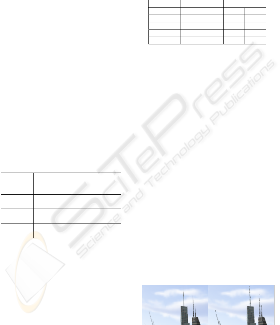
Image Quality. The major drawback of the IBA is
image-quality. In contrast to GBA, sampling artifacts
are introduced while creating the projections. This is
especially problematic for wire-frame renderings or
NPR techniques such as hatching or similar. Figure 4
shows the advantage of GBA over IBA.
Memory Footprint. A further criteria considers the
memory footprint for data related to the rendering
technique, e.g., texture size and geometry. This is
an important criteria for applications that use out-of-
Figure 4: Comparison of the image quality between the
geometry-based (left) and image-based approach (right).
The screen shots are conducted using a cube map texture
of 2048
2
pixels on a target resolution of 1600 × 1200 pix-
els.
INTERACTIVE STEREO RENDERING FOR NON-PLANAR PROJECTIONS OF 3D VIRTUAL ENVIRONMENTS -
With a Comparison of Image- and Geometry-based Approaches
203

core rendering mechanisms. The footprint of the IBA
can be considered constant. It depends on the tex-
ture resolution s, the precision per color channel b,
the number of color channels c, and the number of
raster layers l. The footprint can be approximated
by: O
IBA
(l, s, b, c) = 2 · l · c · b · s
2
byte without mip-
maps. This parametrization enables the user to bal-
ance the trade-off between image quality and memory
consumptions, as well as the runtime complexity.
The memory footprint of the GBA is dynamically
view-depended and scales linearly with the number
of input triangles t. Further, memory footprint de-
pends on the average rate of primitive amplification r
(for a 180
◦
cylindrical projection r = 1.5 −2), and the
size of each triangle in an intermediate data structure
i = 16 byte. The amount of additional memory can
be approximated by: O
GBA
(t, r, i) = t · r · i. Following
to that, the space complexity of the GBA is indepen-
dent of rendering a single NPP or a stereo pair of NPP.
For the complex model (3,210,162 triangles) the addi-
tional memory requirement for a 180
◦
panorama pro-
jection is O
GBA
=∼ 69 MB. This corresponds to four
RGBA raster layers with 1024
2
pixels resolution. For
a higher FOV: O
GBA
< O
IBA
is valid in any case.
6 CONCLUSIONS
This paper presents an overview for creating stereo
renderings of non-planar projections with image-
based and geometry-based rendering techniques. In
particular, it describes the implementation of a single-
pass image-base rendering technique as an extension
to an existing framework. We evaluate the perfor-
mance of this technique with respect to the number of
input triangles. We further present a comparison be-
tween geometry-based and image-based approaches
for generating stereo pairs with respect to of four dif-
ferent criteria.
This comparison shows that both approaches are
capable of rendering stereographic non-planar projec-
tions. The GBA is predominant over IBA in the range
of functionality with respects to stereo rendering, the
quality of the output images, as well as the render-
ing performance. The IBA has advantages consider-
ing the constant space and low implementation com-
plexity. A disadvantage of both rendering techniques
is the limitation to polygonal scenes only. They can-
not be applied directly to volume rendering without
major changes.
Following to these results, we consider the GBA
more suitable for stereo rendering of non-planar pro-
jections than the IBA. According to our performance
measurements, both approaches achieve satisfying
results for 3D scenes of the medium complexity
(500,000 triangles).
REFERENCES
Bimber, O., Wetzstein, G., Emmerling, A., and Nitschke, C.
(2005). Enabling View-Dependent Stereoscopic Pro-
jection in Real Environments. In IEEE ISMAR ’05,
pages 14–23, Washington, DC, USA. IEEE Computer
Society.
Blythe, D. (2006). The Direct3D 10 System. In SIGGRAPH
’06: ACM SIGGRAPH 2006 Papers, pages 724–734,
New York, NY, USA. ACM Press.
Boubekeur, T. and Schlick, C. (2008). A Flexible Kernel
for Adaptive Mesh Refinement on GPU. Computer
Graphics Forum, 27(1):102–114.
Bourke, P. D. and Morse, P. (2007). Stereoscopy, Theory
and Practice. Workshop, VSMM 2007, Brisbane.
Hou, X., Wei, L.-Y., Shum, H.-Y., and Guo, B. (2006).
Real-time Multi-Perspective Rendering on Graphics
Hardware. In EUROGRAPHICS Symposium on Ren-
dering. Blackwell Publishing.
Kessenich, J. (2006). The OpenGL Shading Language Lan-
guage Version: 1.20 Document Revision: 8.
Lorenz, H. and D
¨
ollner, J. (2008). Dynamic Mesh Refine-
ment on GPU using Geometry Shaders. In Proceed-
ings of the 16-th WCSG 2008.
NVIDIA (2008). NVIDIA OpenGL Extension Specifications
for the GeForce 8 Series Architecture (G8x). NVIDIA.
Peleg, S., Ben-Ezra, M., and Pritch, Y. (2001). Omnis-
tereo: Panoramic Stereo Imaging. IEEE Transac-
tions on Pattern Analysis and Machine Intelligence,
23(3):279–290.
Persson, E. (2007). ATI Radeon HD 2000 Programming
Guide. AMD Graphics Products Group.
Spindler, M., Bubke, M., Germer, T., and Strothotte, T.
(2006). Camera Textures. In Proceedings of the 4th
GRAPHITE, pages 295–302. ACM.
Tatarchuk, N. (2007). Real-Time Tessellation on GPU.
In Course 28: Advanced Real-Time Rendering in 3D
Graphics and Games. ACM SIGGRAPH 2007.
Tatarinov, A. (2008). Instanced Tessellation in DirectX10.
In GDC ’08: Game Developers’ Conference 2008.
Trapp, M. and D
¨
ollner, J. (2008). A Generalization
Approach for 3D Viewing Deformations of Single-
Center Projections. In Jos
´
e Braz, N. J. N. and Pereira,
J. M., editors, GRAPP 2008, number 3, pages 162–
170. INSTICC Press.
Yang, Y., Chen, J. X., and Beheshti, M. (2005). Nonlinear
Perspective Projections and Magic Lenses: 3D View
Deformation. IEEE Computer Graphics and Applica-
tions, pages 76–84.
GRAPP 2009 - International Conference on Computer Graphics Theory and Applications
204
