
EXACT ALGEBRAIC METHOD OF OPTICAL FLOW DETECTION
VIA MODULATED INTEGRAL IMAGING
Theoretical Formulation and Real-time Implementation using Correlation Image
Sensor
Shigeru Ando, Toru Kurihara
Department of Information Physics and Computing, University of Tokyo, Tokyo, Japan
Dabi Wei
Department of Control and Systems Engineering, Tokyo Institute of Technology, Tokyo, Japan
Keywords:
Optical flow equation, Weighted integral method, Modulated imaging, Correlation image sensor, Computer
vision, Velocity field measurement, Particle image velocimetry.
Abstract:
A novel mathematical method and a sensing system that detects velocity vector distribution on an optical
image with a pixel-wise spatial resolution and a frame-wise temporal resolution is proposed. It is provided by
the complex sinusoidally-modulated imaging using the three-phase correlation image sensor (3PCIS) and the
exact algebraic inversion method based on the optical flow identity (OFI) satisfied by an intensity image and
a complex-sinusoidally modulated image captured by the 3PCIS. Since the OFI is free from time derivatives,
any limitations on the object velocity and inaccuracies due to approximated time derivatives is thoroughly
avoided. An experimental system was constructed with a 320×256 pixel 3PCIS device and a standard PC for
inversion operations and display. Several experimental results are shown including the dense motion capture
of face and gesture and the particle image velocimetry of water vortices.
1 INTRODUCTION
Optical flow is the two-dimensional velocity field that
describes the apparent motion of image patterns. The
computation of optical flow has been widely studied
since the 1970’s motivated by broad range of applica-
tions such as detection and tracking of an object, sep-
aration from a background or more generally segmen-
tation, three-dimensional motion computation, etc.
One of the most established algorithm for optical flow
determination both theoretically and practically will
be the gradient-based method. It is based on the op-
tical flow constraint (OFC) equation describing the
intensity-invariance of moving patterns. According to
B. McCane(McCane et al., 2001), Horn and Schunk’s
algorithm(Horn and Schunk, 1981) with regulariza-
tion is still one of the best performer among numer-
ous optical flow retrieval algorithms. The determina-
tion of optical flow from conventional image indeed is
structurally very difficult due to the well-known aper-
ture problem. It is stated clearly that optical flow can-
not be retrieved locally for the information we get lo-
cally is one-dimensional; the conventionalOFC deter-
mines the optical flow only in one direction (normal
flow).
Recently, a novel imaging device, three-phase
correlation image sensor (3PCIS), has been devel-
oped(Ando and Kimachi, 2003; Ando et al., 2007),
which can capture, not only the intensity distribu-
tion as a conventional camera, but also produce si-
multaneously a complex-valued image consisting on
quadrature demodulated components of time-varying
intensity distribution. For the optical flow determina-
tion, the 3PCIS can offer an alternative and extended
method to compute locally and therefore quickly the
velocity field. A gradient-based algorithm for the im-
ages from 3PCIS was proposed and its basic proper-
ties were examined using simple images(Wei et al.,
2007). It showed that, contrary to algorithms on con-
ventional image, the computations are operated on
only one frame, thus the temporal differentiation be-
tween frames which is one of the main sources of er-
rors is not required and therefore the accuracy is not
limited by the velocity(Ando et al., 2008).
480
Ando S., Kurihara T. and Wei D. (2009).
EXACT ALGEBRAIC METHOD OF OPTICAL FLOW DETECTION VIA MODULATED INTEGRAL IMAGING - Theoretical Formulation and Real-time
Implementation using Correlation Image Sensor.
In Proceedings of the Four th International Conference on Computer Vision Theory and Applications, pages 481-487
DOI: 10.5220/0001794104810487
Copyright
c
SciTePress

The purpose of this paper is to formulate more ex-
actly the algorithm and its performance and realize
the novel scheme as a real time sensing system with
maximal resolution and examine the performance for
various objects and in various situations. An experi-
mental system was constructed with a 320×256 pixel
3PCIS and a standard PC for necessary computations
and display. Several experimental results are shown
including the dense motion capture of face and ges-
ture, motion detection with extended velocity range,
and the particle image velocimetry of water vortices.
2 THEORY
2.1 Optical Flow Constraint
We consider the brightness f on the object observed
in the moving coordinate system is constant. Then the
optical flow velocity
v
x
,v
y
matches the OFC
(v
x
∂
x
+ v
y
∂
y
) f(x,y,t) + ∂
t
f(x,y,t) = 0 (1)
where, ∂/∂x ≡∂
x
,∂/∂y ≡∂
y
,∂/∂t ≡ ∂
t
.
Traditional optical flow estimation based on the OFC
obtains the unknown velocity v
x
,v
y
from ∂
x
f,∂
y
f,∂
t
f
as the observed quantities. Since one equation is in-
sufficient to retrieve the two unknowns, addition of
some hypothesis such as a locally uniform velocity
field(Lucas and Kanade, 1982), or a smoothness con-
straint of the velocity field (Horn and Schunk, 1981)
is necessary. To obtain ∂
t
f, we need two or more
frames for differencing. Also, this approximation is
the principal source of errors. When the difference is
small, the operation decreases the significant digits.
When it is large, the difference approximation of dif-
ferential is not any more justified and great errors can
be encountered.
2.2 Integral Optical Flow Constraint
To tackle these problems, we introduce a novel
mathematical technique, i.e., the modulated integral
method. It is based on an identity relation
(v
x
∂
x
+ v
y
∂
y
+ ∂
t
) f(x,y,t) = 0
∀
t ∈ [−
T
2
,
T
2
]
↔
Z
T/2
−T/2
{(v
x
∂
x
+ v
y
∂
y
+ ∂
t
) f(x,y,t)}w(t)dt
∀
w(t) (2)
in a frame interval [−T/2,T/2] of an image sensor.
As the modulating function w(t), we can consider an
arbitrary set of complete functions. Here, we restrict
our attention to the complex exponential function set
{e
−jωt
}, ω = 2πn/T, n = 0,1, 2···. Then, evalua-
tion of the second equation using the integral by parts
leads to
Z
T/2
−T/2
{(v
x
∂
x
+ v
y
∂
y
) f(x,y,t)}e
−jωt
dt
+
Z
T/2
−T/2
{∂
t
f(x,y,t)}e
−jωt
dt
= (v
x
∂
x
+ v
y
∂
y
)g
ω
(x,y) + jωg
ω
(x,y)
+
f(x,y,t)e
−jωt
T/2
−T/2
= 0, (3)
where
g
ω
(x,y) ≡
Z
T/2
−T/2
f(x,y,t)e
−jωt
dt (4)
is the correlation image. Here, the third term
is the difference between the instantaneous images
weighted by e
−jωt
at the beginning and end of the
frame, which is not observable. Letting ω = 0, we
obtain another relation on the intensity image as
(v
x
∂
x
+ v
y
∂
y
)g
0
(x,y) + [ f (x,y,t)]
T/2
−T/2
= 0. (5)
The difference term remains although it is not
weighted by e
−jωt
. We show in the next section the
difference terms can be eliminated to obtain an exact
algebraic relation to solve (v
x
,v
y
).
2.3 Direct Algebraic Solution
Assume that we can obtain two images simultane-
ously with modulation frequencies ω = 0 and ω 6= 0.
Since ωT = 2nπ where n is an integer, it follows that
e
jωT/2
= e
−jωT/2
= (−1)
n
at the integral boundaries,
and thus
f(x,y,t)e
−jωt
T/2
−T/2
= (−1)
n
[ f(x,y,t)]
T/2
−T/2
. (6)
Therefore, by combining Eqs. (3) and (5), we obtain
a complex equation
(v
x
∂
x
+ v
y
∂
y
){(−1)
n
g
0
(x,y) −g
ω
(x,y)}
= jωg
ω
(x,y), (7)
which is free from the difference terms. Describing
Eq. (7) in matrix-vector form, we obtain
Av = b, (8)
where
A =
∂
x
((−1)
n
g
0
−ℜg
ω
) ∂
y
((−1)
n
g
0
−ℜg
ω
)
∂
x
ℑg
ω
∂
y
ℑg
ω
v =
v
x
v
y
, b =
−ωℑg
ω
−ωℜg
ω
, (9)
EXACT ALGEBRAIC METHOD OF OPTICAL FLOW DETECTION VIA MODULATED INTEGRAL IMAGING -
Theoretical Formulation and Real-time Implementation using Correlation Image Sensor
481
where ℜ and ℑ denote the real and the imaginary part,
respectively.
Two (real and imaginary) linear equations in it are
sufficient to solve two real unknowns (v
x
,v
y
). Com-
bining with the gradient vector images ∇g
0
(x,y) and
∇g
ω
(x,y), we can compute the unknowns directly
from one pixel and one frame. We hereafter call
Eq.(7) the optical flow identity (OFI). The OFI if free
from time derivative which is a severe source of er-
ror such as the finite differencing between frames and
the temporal aliasing in large motion. For the spatial
derivative in the OFI, the problem is far less suscep-
tive by virtue of spatially dense image data and mostly
ideal FFT-based gradient operation.
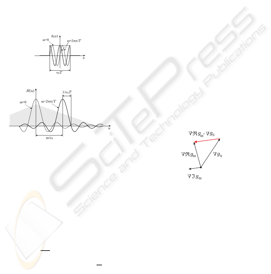
(a) point spread functions
(b) spatial frequency characteristics
Figure 1: Point spread functions (a) and spatial frequency
characteristics (b) in motion direction by means of complex
sinusoidally modulated imaging.
2.4 Modulation Frequency
Performance of the proposed method depends on fre-
quency ω of the modulated imaging with relating to
spatial frequency spectrum of moving objects. This
relation is described by the point spread functions of
motion blur and the corresponding spatial frequency
characteristics:
h(x) ≡ rect(
x
v
x
T
)e
j(ω/v
x
)x
F
←→ H(u) ≡ |v
x
T|sinc(v
x
T(u−
ω
v
x
)). (10)
Fig. 1 shows them when ω = 0 and ω > 0. For ω = 0,
the image is low-pass filtered with bandwidth 2/v
x
T
of the original spectrum (illustrated as a shaded area
in (b)). In another image using ω = 2πn/T (n > 0), it
is band-pass filtered with the same bandwidth 2/v
x
T
but its center at ω/v
x
. According to an increase of ve-
locity v
x
, two spectral bands are shifting toward a low
frequency side. This usually decreases the power of
gradient image, thus decreases the accuracy of veloc-
ity. When the velocity is small or ω is too large, the
spectral band locates in higher frequencies, hence the
power of image and the accuracy of velocity decrease.
Therefore, some optimum values of ω will exist with
relating to the spatial frequency distribution of mov-
ing object.
2.5 Aperture Problem
The aperture problem is arisen when the determinant
of matrix A in Eq. (8) becomes zero. The condition
is illustrated in Fig. 2. Namely, it vanishes when
∇ℜg
ω
−(−1)
n
∇g
0
and ∇ℑg
ω
are parallel. If the mov-
ing pattern is truly uni-directional (same direction in
wide spatial frequency range), the direction of ∇g
ω
and ∇g
0
coincides, thus the aperture problem happens
in the same way as the conventional optical flow de-
tection. When the directions in different frequency
bands are different, however, the directions are differ-
ent, thus the aperture problem can be avoided. In the
proposed method, two frequency bands for g
0
and g
ω
are used, and the aperture problem is only when the
uni-directionalities are common. Therefore, the con-
ditions for aperture problem are relaxed in this sense.
Figure 2: Condition for the aperture problem in the OFI
when n of ωT = 2nπ is even. The velocity is indeterminate
when ∇ℜg
ω
−∇g
0
is parallel to ∇ℑg
ω
.
3 CORRELATION IMAGE
SENSOR
3.1 Principle
As shown in Fig. 3(a), the 3PCIS consists of a pho-
todiode PD, multiplier transistors Q
1
,Q
2
, and Q
3
, ca-
pacitors of the same capacitance C, and readout tran-
sistors SW
1
,SW
2
, and SW
3
. The photo-generated cur-
rent I from the PD is split by Q
1
,Q
2
, and Q
3
in pro-
portion to their respective gate-source voltages V
1
,V
2
,
and V
3
into the drain currents
VISAPP 2009 - International Conference on Computer Vision Theory and Applications
482
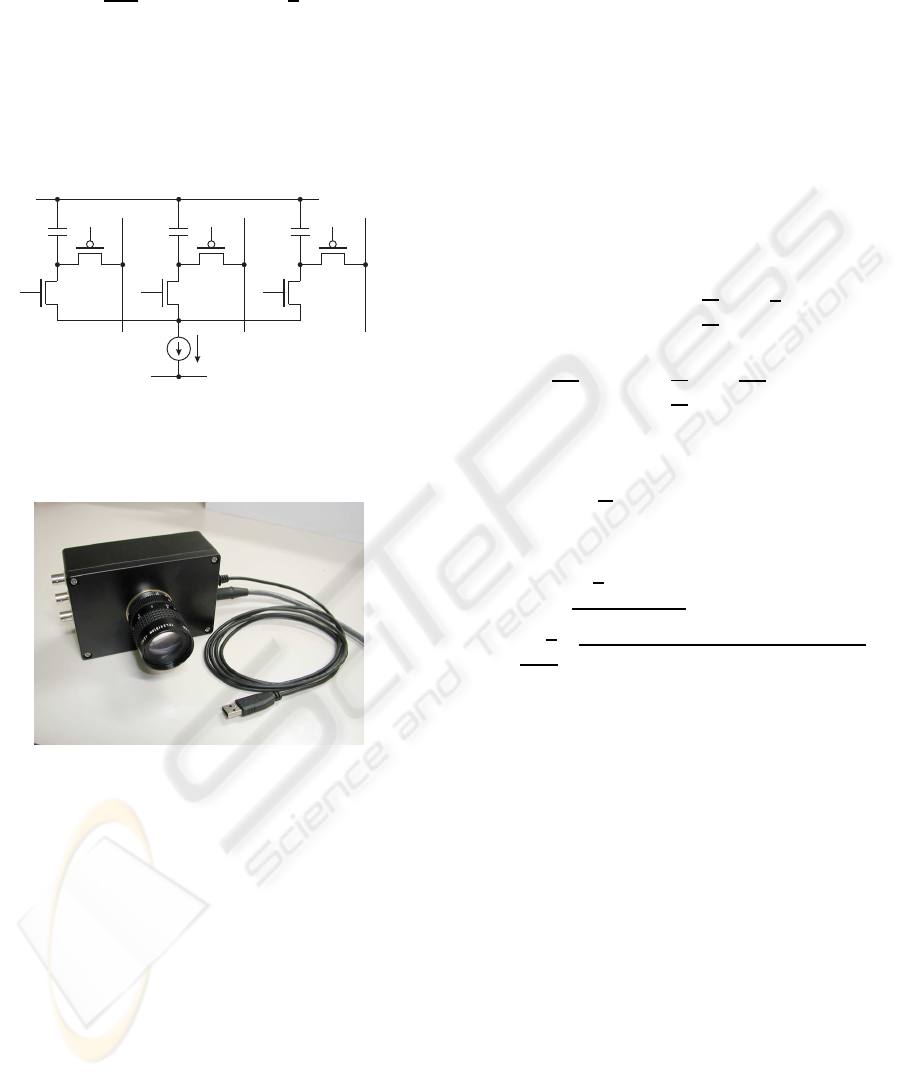
I
1
I
2
I
3
≃ −
qκ
3kT
I(V
1
−
¯
V)
I(V
2
−
¯
V)
I(V
3
−
¯
V)
+
1
3
I
I
I
(11)
(k: Boltzmann constant, T: absolute temperature, q:
electron charge, κ: gate coefficient,
¯
V ≡ (V
1
+ V
2
+
V
3
)/3), and accumulated at three independent capaci-
tors C. By activating SW
1
,SW
2
, and SW
3
, charges are
transferred to external capacitors and the capacitors C
are reset.
I
C
DD
V
1
2
SW
Q
PD
V
1
V
C
Q
2
3
SW
1
SS
V
ysel ysel
=0V
out
3
out
1
C
Q
3
3
V
ysel
out
2
SW
2
=3.3V
Figure 3: The pixel circuit of 3PCIS. V
1
,V
2
, and V
3
are the
reference inputs and I is an input from the PD. The charges
stored in the capacitors C are the sums of the mean intensity
<I > and correlation <IV
i
> between I and V
i
(i = 1,2,3).
Figure 4: Lock-in camera using 3PCIS. This enables paral-
lel correlation detection with two arbitrary analog orthogo-
nal reference signals supplied in the three-phase form. The
three correlation outputs are A/D-converted and transferred
to a PC via the USB.
The 200 ×200 pixel device was fabricated through
the 0.35µm 2 poly-3 metal (2P3M) CMOS pro-
cess provided by VLSI Design and Education Center
(VDEC), Univ. Tokyo, and 320 ×256 devices were
fabricated through the 0.35µm 2P3M CMOS imager
process by SHARP Corp., Japan. Several parameters
and performances of these devices and cameras are
summarized in Table 1.
3.2 Amplitude / Phase Recovery
Three outputs from each pixel of the 3PCIS can be
converted into a background (time-averaged) inten-
sity, a correlation amplitude, and a correlation phase
as follows. Let the time-varying intensity on a pixel
at the coordinates (x,y) be
f(t) = Acos(ωt + φ) + B+ ξ(t). (12)
here, ω is the frequency of the modulated light, φ is
the phase, A is the amplitude, B is the stationary back-
ground intensity, and ξ(t) denotes any time-varying
light components except for the frequency ω and DC.
As the reference signals of the 3PCIS, we input three
sinusoidal waves whose frequency is ω and whose ini-
tial phases are 0,2π/3, and 4π/3. Then, the 3PCIS
generates three outputs.
R
1
R
2
R
3
= < f(t)
cosωt
cos(ωt +
2π
3
)
cos(ωt +
4π
3
)
+
1
3
f(t)
f(t)
f(t)
>
=
AT
2
cosφ
cos(φ−
2π
3
)
cos(φ−
4π
3
)
+
BT
3
1
1
1
(13)
Hence, the intensity is expressed as
B =
1
T
(R
1
+ R
2
+ R
3
), (14)
and the correlation amplitude A and the phase φ
are obtained as
φ = tan
−1
(
√
3(R
2
−R
3
)
2R
1
−R
2
−R
3
) (15)
A =
2
√
2
3
q
(R
1
−R
2
)
2
+ (R
2
−R
3
)
2
+ (R
3
−R
1
)
2
.
(16)
The calculations are performed in real time by a PC
from the A/D-converted outputs of the 3PCIS.
4 IMPLEMENTATION
An experimental system was constructed using a
320 × 256 pixel 3PCIS and a PC (Core2 Duo
(TM)
@3.0GHz). Fig. 5 shows the block diagram of the
camera and the algorithm in the PC.
4.1 “Phase-Stamp” Imaging
Usual applications of 3PCIS are to 2-D active sensing
schemes in which reflected lights of modulated illu-
mination or returned lights modulated by a given per-
turbation on the object are observed(Kimachi et al.,
2001; Kimachi et al., 2002; Ando et al., 2007; Ki-
machi, 2007). Contrastively, the phase-stamp imag-
ing is a passive scheme. Moving objects are imaged
EXACT ALGEBRAIC METHOD OF OPTICAL FLOW DETECTION VIA MODULATED INTEGRAL IMAGING -
Theoretical Formulation and Real-time Implementation using Correlation Image Sensor
483
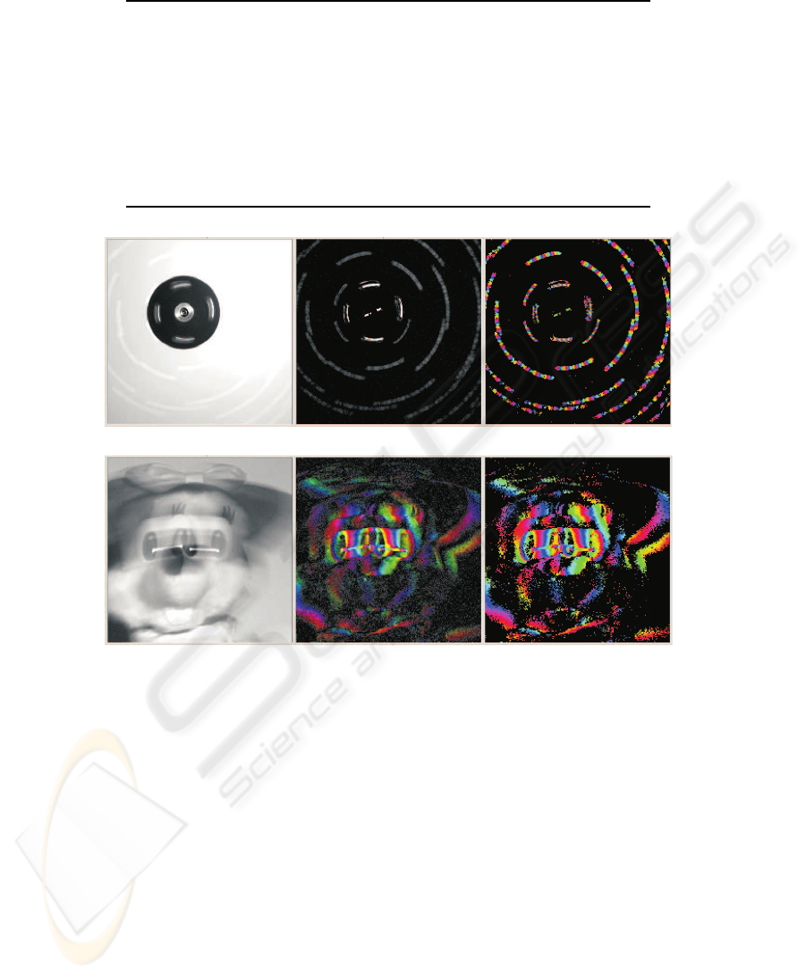
Table 1: Specification of 3PCISs and lock-in cameras used in experiments.
process CMOS 0.35µm 2P3M CMOS 0.35µm 2P3M
image size 200×200 320×256
pixel size 40µm×40µm 24µm×24µm
chip size 9.8mm×9.8mm 9.81mm×9.81mm
correlation SNR — ∼30dB
phase SNR ∼44dB ∼47dB
cutoff frequency ∼400×scan frequency ∼200×scan frequency
correlation output charge readout, 3φ charge readout, 3φ
A/D conversion external (12bit, 3ch) internal (10 bit, 3ch)
frame rate 1.875∼15 frames/s 5.7∼183.1 frames/s
(a) rotating dots (ω = 8π/T)
(b) horizontally moving toy (ω = 2π/T)
Figure 6: Examples of phase stamp imaging. From left to right of each, intensity image, correlation amplitude image, and
correlation phase image (phase is indicated by hue).
while supplying sinusoidal reference signals to the
3PCIS.
The role of modulated imaging scheme can be
readily understood when the objects moving are
sparsely distributed points. When they are imaged
with s sinusoidal reference signal with a fixed fre-
quency, the passage time of a point is recorded as
the phase of correlation image along its lucus. Sta-
tionary objects and background do not appear in the
correlation image although it is involved in the in-
tensity image. An example is shown in Fig. 6(a).
The objects are random dots on a rotating disk. The
reference frequency is such that four cycles of the
sinusoid is involved in a frame. In the correlation
phase images, continuous phase distributions [0,8π]
are recorded along the loci.
For more complex objects, simple correspondence
between time and phase like above is lost because the
loci of their components overlap each other. Never-
theless, rich information is involved in a particular
manner described in the previous section. Fig. 6(b)
shows an example. The correlation amplitude images
are shown with the hue corresponding to the correla-
tion phase. When the toy is moving, significant am-
plitudes appear along the boundary in the correlation
image. In their perpendicular direction, the phase is
changing regularly in proportion to the velocity. Con-
trarily in the intensity images, these regions are cap-
tured only as the blur.
4.2 Differential-of-Gaussian Filtering
This is to obtain gradients and smoothed versions of
g
0
(x,y) and g
ω
(x,y). The filtering is performed in
VISAPP 2009 - International Conference on Computer Vision Theory and Applications
484
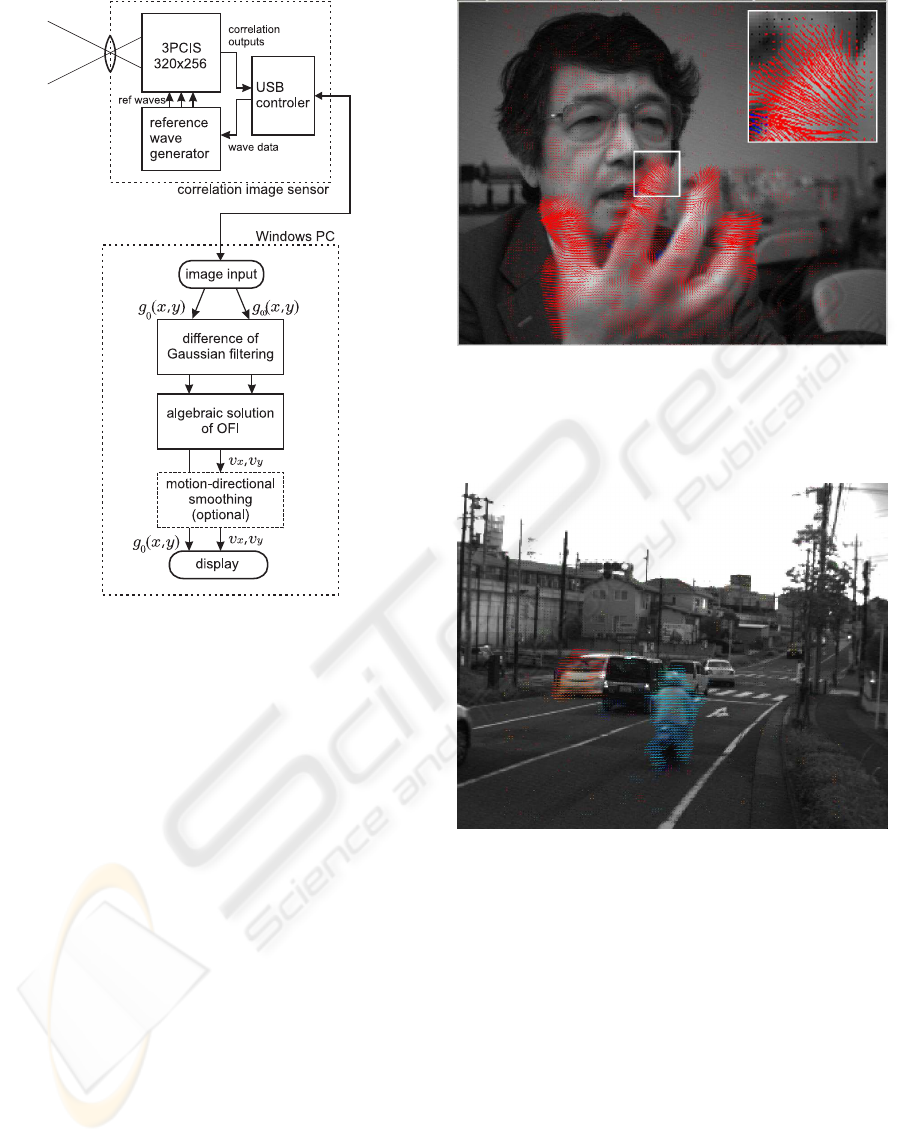
Figure 5: Block diagram of correlation camera using 3PCIS
and algorithms performed by a PC.
Fourier domain using 2-D FFTs. The smoothing pa-
rameter σ (rms size of Gaussian kernel) is variable.
In most applications, σ = 0.5 [pixel length] is an ap-
propriate choice to make a full use of spatial reso-
lution. For fast moving object with low spatial fre-
quency components,σ can be increased to fit the spec-
tral passband to lower spatial frequency components.
The use of consistent gradient operators(Ando, 2000)
is an alternative choice for this stage.
4.3 Motion-directional Smoothing
During a frame time, each object keeps moving in
its motion direction. This causes a smoothing ef-
fect in which the motion vector field is mostly con-
tinuous in the motion direction. Conversely speak-
ing, we can smooth the motion vector field without
a resolution loss so that noises are reduced and esti-
mates are stabilized. In our system, it is performed in
conjunction with the iterative local least squares esti-
mate with varying spatial window(Lucas and Kanade,
1982; Ando, 1986). The window area is elongated
along the previously estimated motion direction and
the motion vector is estimated again.
Figure 7: An example of optical flow detection of face and
gesture. Detected optical flow vectors at every two pixels
are indicated by directed lines. The length and direction are
equal to a movement in a frame. The result is obtained in
real time.
Figure 8: An example of optical flow detection of a traffic
scene. The direction of motion is indicated by hue of line
along with its length and direction.
5 EXPERIMENTS
5.1 Natural Scenes
Facial motion or gesture are a typical target of opti-
cal flow detection that requires high spatio-temporal
resolution and wide dynamic range of motion veloc-
ity. Fig. 7 shows an example of application result.
Detected nonzero optical flow vectors at every two
pixels are indicated by directed lines at the pixels.
The length and direction are equal to a movement in
a frame. Without motion-directional smoothing, the
detection rate of 14 frame/s (a half of frame rate) is
EXACT ALGEBRAIC METHOD OF OPTICAL FLOW DETECTION VIA MODULATED INTEGRAL IMAGING -
Theoretical Formulation and Real-time Implementation using Correlation Image Sensor
485
achieved for 128 ×128 motion vectors. Simultane-
ous processing of image input, calculation, and dis-
play will increase the speed upto the frame rate. With
the motion-directional smoothing, the speed reduces
to about 7 frame/s. Fig. 8 shows another result for a
traffic scene. A man on a motorbike going rightward
and a car coming from behind a waiting car are cap-
tured well by length and direction (indicated by hue)
of the velocity vectors.
5.2 Rapidly Moving Object
By an appropriate selection of sinusoidal frequency,
this system can be adjusted to a wide range of mo-
tion speed. Fig. 9 and Fig. 10 show examples to a
rotating disk when the rotation is stopped, slow, and
fast. For clarity, the direction of motion is indicated
by hue of line along with its length and direction.
The test chart on the disk is so designed that both
the spatial frequency and temporal frequency when
it is rotated is larger in the central zone. When the
rotation speed is slow, most temporal frequencies are
involved in correlation bandwidth of n = 1 sinusoid
(ω is equal to the frame frequency). But when it is
high, the frequency generated at the central exceeds
the bandwidth. In this case, we doubled (n = 2) the
reference signal frequency to capture the high tem-
poral frequency as shown in Fig. 10. Optical flow at
there is captured successfully. But this causes lower
cutoff in the marginal zone, hence the optical flow is
not detected there.
5.3 Particle Image Velocimetry
The proposed sensor is very suitable for the particle
image velocimetry (PIV). Fig. 11 shows an example
of real-time measurement of velocity distribution of
a water surface marked by aluminum powder is de-
tected. The direction of motion is indicated by hue
of line along with its length and direction. In conven-
tional PIV, the velocity is obtained only particle-wise
by tracking the centroid of each particle. Contrarily
in this technique, the resolution is not limited by the
particle size and density. Except for pixels where no
fraction of particle is passing in a frame time, the opti-
cal flow can be detected based on the spatio-temporal
intensity changes.
6 SUMMARY
A novel sensing scheme and algorithm for optical
flow detection with maximal spatio and temporal res-
olution was proposed. An experimental system was
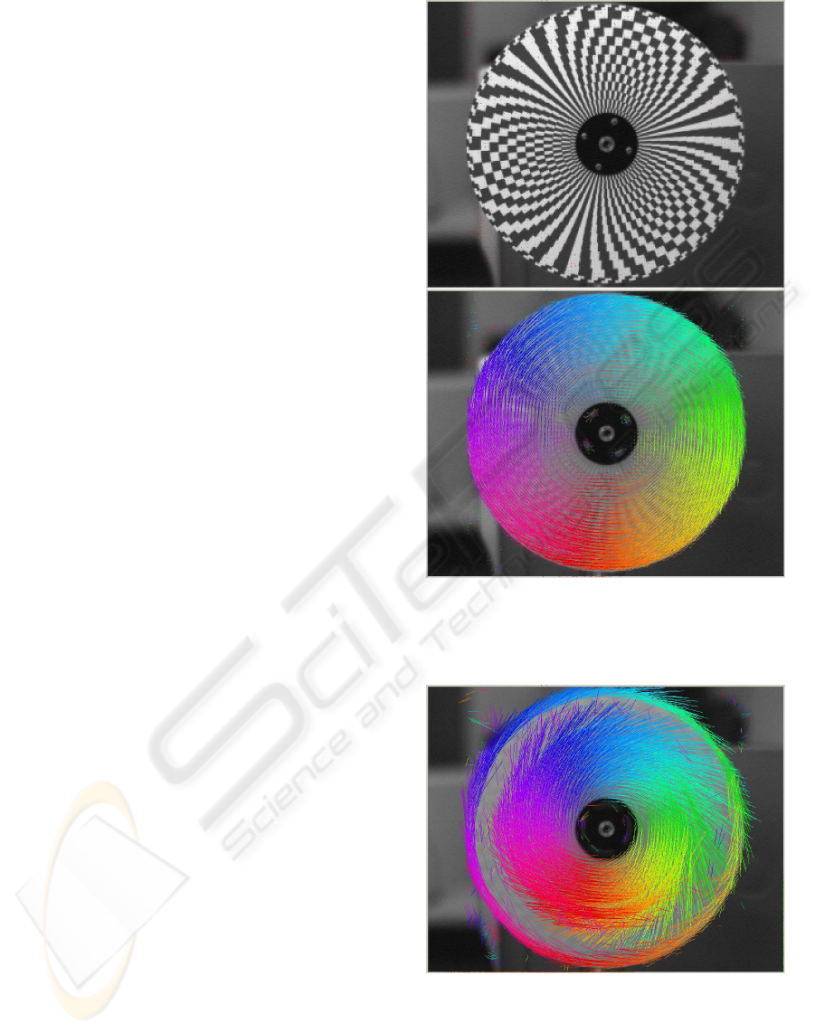
Figure 9: Optical flow of a rotating disk with wide ranging
spatial frequencies. The upper image shows the object when
it is stopped, and the lower image shows the detection result
of optical flow. The direction of motion is indicated by hue
of line along with its length and direction.
Figure 10: Optical flow of fast rotating disk. The object is
same as Fig. 9. The reference signal frequency is increased
to capture the high temporal frequency of the central zone.
The frequency is below cutoff in the marginal zone, hence
the optical flow is not detected.
constructed with a 320 ×256 pixel 3PCIS. Several
experimental results are shown using this system.
VISAPP 2009 - International Conference on Computer Vision Theory and Applications
486
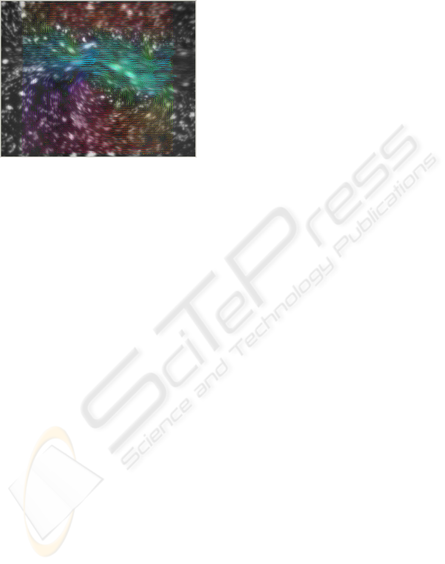
Figure 11: An example of real-time particle image ve-
locimetry. Velocity distribution of a water surface marked
by aluminum powder is detected. The direction of motion is
indicated by hue of line along with its length and direction.
Device development of this work was supported by
VLSI Design and Education Center, University of
Tokyo, and Advanced Technology Research Labora-
tory, Sharp Corporation.
REFERENCES
Ando, S. (1986). A velocity vector field measurement sys-
tem based on spatio-temporal image derivative. In
Trans. SICE, vol.22, pp.1330-1336.
Ando, S. (2000). Consistent gradient operators. In IEEE
Trans. Pattern Anal. Machine Intell., vol.22, no.3,
pp.252-265.
Ando, S. and Kimachi, A. (2003). Correlation image sen-
sor: Two-dimensional matched detection of amplitude
modulated light. In IEEE Trans. Electron Devices,
vol.50, no.10, pp.2059-2066.
Ando, S., Nara, T., Ono, N., and Kurihara, T. (2007). Real-
time orientation-sensitive magneto-optic imager for
leakage flux inspection. In IEEE Trans. Magnetics,
vol.43, no.3, pp.1044-1051.
Ando, S., Wei, D., and Masurel, P. (2008). Optical flow
detection via complex-sinusoidally modulated imag-
ing and its realization with correlation image sensor.
In Trans. IPSJ, Computer Vision and Image Media,
vol.49, no.6, p.13-21.
Horn, B. K. P. and Schunk, B. G. (1981). Determining op-
tical flow. In Artificial Intell., vol.17, pp.185-203.
Kimachi, A. (2007). Real-time heterodyne imaging inter-
ferometry: focal-plane amplitude and phase demodu-
lation using a three-phase correlation image sensor. In
Applied Optics, vol.46, no.1, pp.87-94.
Kimachi, A., Imaizumi, T., Kato, A., and Ando, S. (2002).
Spectral matching imager using correlation image
sensor. In Trans. IEEJ, vol.122-E, no.4, pp.200-206.
Kimachi, A., Kurihara, T., Takamoto, M., and Ando, S.
(2001). A novel range finding system using correla-
tion image sensor. In Trans. IEEJ, vol.121-E, no. 7,
pp.367-375.
Lucas, B. D. and Kanade, T. (1982). An iterative image
registration technique with an application to stereo vi-
sion. In Proc. 7th IJCAI, pp.674-679.
McCane, B., Novins, K., Crannitch, D., and Galvin, B.
(2001). On benchmarking optical flow. In Comput.
Vis. Image Underst., vol.84, no.1, pp.126-143.
Wei, D., Masurel, P., Kurihara, T., and Ando, S. (2007).
Optical flow determination with complex-sinusoidally
modulated imaging. In Trans. IEICE, vol.J90-D, no.8,
pp.2009-2018.
EXACT ALGEBRAIC METHOD OF OPTICAL FLOW DETECTION VIA MODULATED INTEGRAL IMAGING -
Theoretical Formulation and Real-time Implementation using Correlation Image Sensor
487
