NOISE REMOVAL IN CRACK DETECTION ALGORITHM
ON ASPHALT SURFACE IMAGES
Siwaporn Sorncharean and Suebskul Phiphobmongkol
Department of Computer Engineering, Chulalongkorn University, Pathumwan, Bangkok, Thailand
Keywords: Image Processing, Crack Detection, Noise Removal, Asphalt Surface.
Abstract: This paper presents an image processing technique for noise removal in the intermediate stage of crack
detection algorithm. Unlike noise in other domains, noise in this kind of image is unique in terms of size and
dispersal. This technique is based on Newton’s theory of universal gravitation. The technique highlights
noise within an image by giving low values to noise objects while giving high values to cracks, thus,
making it simple to indicate an object as a noise or a crack. This method gave good results in removing
noise from crack segmentation algorithm.
1 INTRODUCTION
Highway management system is typically used for
estimating the budget and for making maintenance
plan. Like all systems, the input of correct data is
essential. Submitting incorrect raw data can envisage
circumstances that would cause grave financial
distress to local, regional, and national governments.
When looking at the area of pavement distress,
visual inspection by human inspectors is time
consuming, requires too many professional
inspectors, and is financially restrictive. Moreover,
distress classifications and measurement are
subjective. Two inspectors may give different results
of distress information even if they are looking at the
same thing.
To solve these problems, automatic crack
monitoring systems were applied. An automatic
system (Pynn, 1999) can be separated into two
phases. In the first phase, the system collected road
surface images using a camera installed on a survey
vehicle. In the second phase, an automatic
processing of collected images was performed to
locate and measure distress.
A major problem of this automatic system was
the accuracy of distress information from automatic
processing of collected images. Many researches
were done to solve this problem by using image
processing techniques. Most crack detection
algorithm consisted of two parts, segmenting crack
lines and identifying them. For example, edge
detectoin algorthim (Yu, 2007), wavelet transform
technique (Subirats, 2006) and grid cell analysis
(Xu, 2006) (Sorncharean, 2008) were used to find
crack lines, and artificial intelligence techniques
(Zhang, 2004) (Tomikawa, 1999) (Meignen, 1997)
were used to classify cracked area.
Since the segmentation phase output still
contained noise, as a result, cracked areas were
misclassified and accuracy of crack detection
algorithm was reduced. To solve the problem, this
paper proposed a technique to remove noise in the
intermediate stage of crack detection algorithm. This
technique is based on Newton’s theory of universal
gravitation.
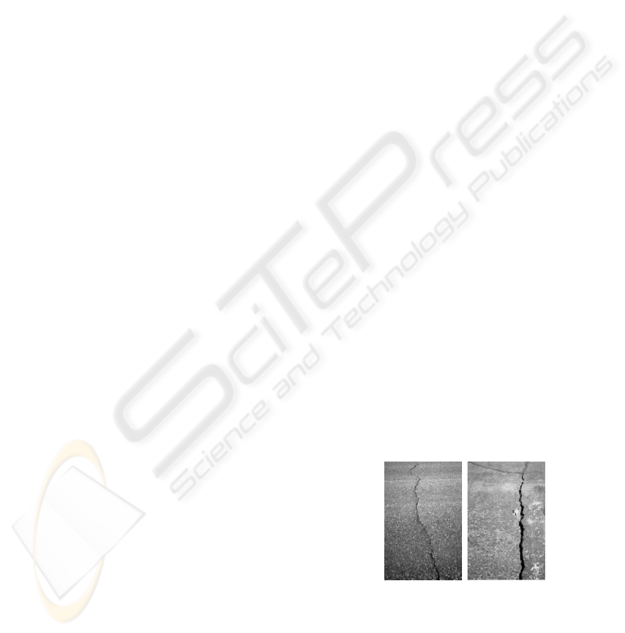
2 CRACK DISTRESS ON
ASPHALT SURFACE IMAGES
Figure 1: Example of crack on asphalt surface images
(transportation information center, 2002).
Crack is one of the major categories of common
asphalt pavement surface distress. Crack may result
from weathering, aging, or structural caused by
repeated traffic loadings. Most inspectors who
evaluate pavement surface conditions identify
269
Sorncharean S. and Phiphobmongkol S. (2009).
NOISE REMOVAL IN CRACK DETECTION ALGORITHM ON ASPHALT SURFACE IMAGES .
In Proceedings of the Fourth International Conference on Computer Vision Theory and Applications, pages 269-272
DOI: 10.5220/0001797902690272
Copyright
c
SciTePress
different types of crack, and link them to causes and
appropriate maintenance. There are six types of
crack, i.e. transverse, reflection, slippage,
longitudinal, block, and alligator crack.
(Transportation Information Center, 2002)
When capturing pavement images, crack line
appeared in an image as long strip of pixels which
perceptibly darker than background, as shown in 2.
Crack segmentation phase in the crack detection
algorithm try to extract crack lines using the crack
feature, darker lines on the background.
Unfortunately, some dark strips or spots are also
sorted out. It is hard to distinguish crack lines and
dark strips and to identify crack type with
confounding objects.
3 PRIOR WORK
The prior work (Sorncharean, 2008) of this research
involved a pavement survey system using area scan
cameras. Each camera had a resolution of 1024 x
960 pixels. A camera covered approximately 1.86 x
1.75 square meters with ground resolution of about
1.8 mm/pixel. The image processing was run on an
Intel Centrino Duo 2.16 GHz computer with 1GB
RAM.
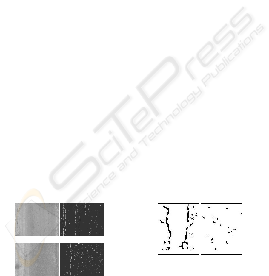
The prior work focused on crack segmentation
phase with enhanced grid cell analysis. The results
of the work, as shown in Figure 2, showed that the
segmentation phase could extract cracks from the
sample images but there were still some noise in the
result images which could confound crack
identification algorithm in the later step.
To handle this problem, noise removal phase
was proposed and applied between the crack
segmentation phase and crack identification phase.
This phase helps removing noise in the intermediate
result images which are the input of the crack
identification phase.
(a)
(b)
Original Result
Figure 2: Examples of noise in result images.
4 THE PROPOSED APPROACH
Noise in the intermediate result is a problem for
classifying crack type. Unlike white noise or salt and
pepper noise (Gonzalez, 1992), this type of noise
cannot be removed by using filters. Noise is a small
object that looks like small piece of crack, thus,
Figure 2: Example of Crack on Asphalt Surface Images
(Transportation Information Center, 2002).
Crack and non-crack objects are blended
together. As a result, it is difficult to identify the
cracking area.
Figure 2 shows the result images with noise
objects from the prior work. Noise could be caused
by dark spots on the original image, as shown in
Figure 2 (a). Another cause of noise is other types of
pavement distress. For example, Figure 2 (b) shows
an original image with a patched area which causes
the result image containing too much noise.
4.1 Crack Appearance
From segmentation process, an object is mostly
justified to be a crack if it has a huge area (pixel
counts), but this is not always true. For example,
large objects (a), (e), and (g) in 0(a) are parts of
crack lines, but many small objects in 0(a) are also
parts of crack lines too.
In contrast to 0(a), 0(b) shows noise objects on
non-cracking area. However, these objects look like
small objects in 0(a), e.g. object (b), (c), and (h). The
distinction between the small objects in 0(a) and
0(b) is the dispersal of the objects themselves. Small
objects in 0(a) are close to huge objects, while the
objects in 0(b) spread over the whole region. From
this distinction, the technique for telling the
difference between crack and non-crack objects was
proposed with an assumption that a crack object is
an object which has large area or stays close to a
large object.
(a) (b)
Figure 3: Enlarged Elements.
4.2 Crack Gravitation
Modern physics describes gravitation as a natural
phenomenon that objects attract each other with a
VISAPP 2009 - International Conference on Computer Vision Theory and Applications
270
force of gravitational attraction. The Newton's
theory of universal gravitation states that the force is
directly dependent upon the masses of both objects
and inversely proportional to the square of the
distance between their centers (Drakos, 1999).
Like force of gravitational attraction, a crack
object is considered as part of a crack line or not by
its area and the distance between it and other
objects. For the purpose of noise removal,
gravitation feature is applied to calculate
gravitational force between each pair of objects. If
the force is strong enough, it indicates that the object
is close to a large object and is considered a crack.
4.3 Gravitation Feature
If an object A has a pixel area of
a
a and an object B
has a pixel area of
b
a , then the magnitude of
gravitational force feature
f
on object A will be
directed toward object B as shown below,
2
ab
aa
f
r
=
(1)
where
r is the shortest distance among the distance
between the two tips of object A and B.
Since the gravitational force is directly
proportional to the product of pixel areas of the two
interacting objects, larger objects will attract each
other with a greater gravitational force. In contrast to
the area, the force is inversely proportional to the
square of the shortest distance,
r , as described
above. Farther distance will result in weaker
gravitational forces.
Due to the fact that most crack objects are
narrow and almost aligned, the center of gravitation
is then applied to the tips of the objects in order to
increase gravitational force to the surrounding
objects. With this concept, the gravitational force
Figure 4: Objects on a Crack Line.
Table 1: Object information for Figure 4.
Interacting
Object Number
Area
(pixel)
Distance
(pixel)
Gravitational
Force
(Feature Value)
(1) 682.00 13.04 1,207.54
(2) 489.00 31.58 147.63
(3) 1,444.00 160.59 16.85
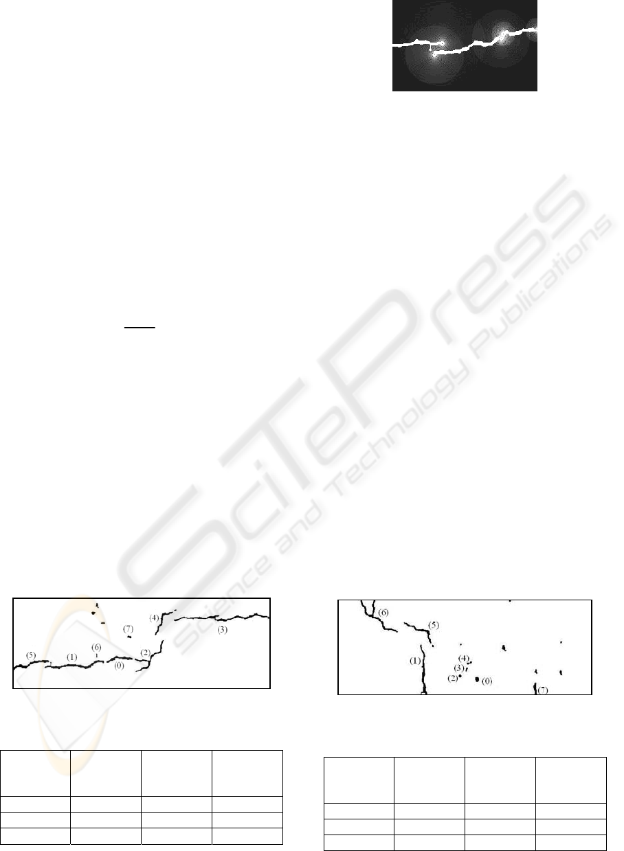
Figure 5: Crack gravitation.
abruptly changes with the distance, thus, make it
easier to perceive an object as a crack.
Figure 5 shows an example of applying
gravitational force feature to the crack objects.
Crack objects are displayed in white object on the
black background. The gravitational force feature
applied to the tip of the objects. The feature values
are shown as grey level. The brighter of the pixel,
the higher value of the feature. The feature shows
that bigger crack object gives stronger gravitational
force value, as can be seen in 0 where strong force
resulted from big objects can reach farther objects.
Moreover, closer crack objects tend to present
higher value of the feature.
In order to classify crack, the area and the
gravitational force are considered. Large area objects
or strong gravitational forces are signs of crack
objects. Otherwise, the objects are indicated as
noise. In other words, weak gravitational forces
show a characteristic of random orientation of small
objects.
5 EXPERIMENTAL RESULT
To test the capability of this feature, the concept was
applied to every pair of crack objects in an example
image to show the feature value. 0 shows an
example of noisy image. Considering object (0) in
Figure 6: Objects on Non-Crack Line.
Table 2: Object information for Figure 6.
Interacting
Object Number
Area
(pixel)
Distance
(pixel)
Gravitational
Force
(
Feature Value)
(1) 1,444.00 141.17 4.46
(2) 32.50 37.01 1.46
(3) 16.00 30.87 1.03
NOISE REMOVAL IN CRACK DETECTION ALGORITHM
ON ASPHALT SURFACE IMAGES
271

Figure 4, it is on a crack line with an area of 301
pixels. The other significant object information is
shown in Table 1 with their feature values arranged
in descending order. The object (1) is on the same
crack line as the considered object (0). Moreover,
the object (1) is the closest object to the object (0).
Unlike object (1), the object (2) is smaller and
farther than the object (1). As a result, object (1)
gives a value of 1,207.54 which is the highest value
of the gravitational force towards object (0) while
the object (2) gives a value of 147.63 which is a
much smaller value.
Looking at object (3) in the 04, it is the biggest
object but very far away from the considered object
(0). Consequently, it gives a value of 16.85 which is
a small amount of feature value.
0 shows the object where the considered object
(0) is noise object with an area of 61 pixels. Partial
object information is shown in Table 2. Since the
considered object (0) is small, the biggest object
gives a little feature value, 4.46, compared to feature
value of the object (1), which is 1,207.54, in 0.
Due to a high range of the feature value, it has
the ability to distinguish an object as a noise object
or a crack. This concept was applied to the example
images in 0. 0 column (a) shows the original
pavement surface with the crack lines. 0 column (b)
shows the result image with too many noise objects
from crack detection algorithm. After applying this
feature for removing noise, the crack lines appear
obviously. The results are shown in 0 column (c).
6 CONCLUSIONS
This paper introduces an image processing feature
for noise removal in the intermediate result images
of the crack detection algorithm. Unlike normal
noise, noise of this kind of image is unique in terms
of size and dispersal. This feature of noise removal
is based on the theory of universal gravitation. This
theory is applied to the objects for keeping crack
objects separated form noise.
(a) (b) (c)
Figure 7: Result images.
Applying this feature to noisy images, the crack
lines are easier to be notice and classified in the
identification phase. With less noise, the
identification algorithm gives more accurate output
for highway management system. In the big picture,
the proposed method helped improve the accuracy of
the crack detection algorithm (Sorncharean, 2008)
and providing more reliable information to the
highway management system.
REFERENCES
Pynn, J., Wright, A., Lodge, R., 1999. Automatic
identification of cracks in road surfaces. In 7th
International Conference on Image Processing and Its
Applications.
Yu, S.-N., Janga, J.-H., Han, C.-S., 2007. Auto inspection
system using a mobile robot for detecting concrete
cracks in a tunnel. In Automation in Construction.
Subirats, P., Dumoulin, J., Legeay, V., Barba, D., 2006.
Automation of Pavement Surface Crack Detection
using the Continuous Wavelet Transform. In IEEE
International Conference on Image Processing 2006.
Xu, B., Huang, Y., 2006. Automatic Inspection of
Pavement Cracking Distress. In Journal of Electronic
Imaging, vol. 15.
Sorncharean, S., Phiphobmongkol, S., 2008. Crack
Detection on Asphalt Surface Image Using Enhanced
Grid Cell Analysis. In DELTA2008, IEEE
International Symposium on Electronic Design, Test
and Applications.
Zhang, H. G., Wang, Q., 2004. Use of Artificial Living
System for Pavement Distress Survey. In 30th Annual
Conference on Industrial Electronics Society 2004.
IEEE Computer Society.
Tomikawa, T., 1999. A study of road crack detection by
the meta-genetic algorithm. In AFRICON. IEEE.
Meignen, D., Bernadet, M., Briand, H., 1997. One
Application of Neural Networks for Detection of
Defects Using Video Data Bases: Identification of
Road Distresses. In Proceedings of the 8th
International Workshop on Database and Expert
Systems Applications. IEEE Computer Society.
Transportation Information Center, University of
Wisconsin – Madison, 2002. Pavement Surface
Evaluation and Rating Asphalt Roads, PASER
Manual.
Gonzalez, R. C., Woods, R. C., 1992. Digital Image
Processing.
Drakos, N., 1999. Newton's Law of Gravity. Online
Document URL: http://theory.uwinnipeg.ca/
mod_tech/node54.html.
VISAPP 2009 - International Conference on Computer Vision Theory and Applications
272
