DIGITAL IMAGE STABILIZATION IN A VIDEO-STREAM
Stabilization of (Undesirable) Image Movements in a Video-Stream
Martin Drahansky and Filip Orsag
Faculty of Information Technology, Brno University of Technology, Bozetechova 2, 61266, Brno, Czech Republic
Keywords: Image, Stabilization, Video-stream, DSP, FPGA.
Abstract: This paper deals with an image stabilization for video based tracking systems. At the beginning an introduc-
tion to the image stabilization is stated. Short description of known algorithms for image stabilization fol-
lows including our solution based on these methods with some optimizations. At the end, we represent a
suitable hardware platform, which was developed and constructed by us and uses DSP, FPGA and SDRAM.
The connection of our software and our hardware is new and very promising.
1 INTRODUCTION
Classical security monitoring systems using video-
cameras are well known. Resolution of such cameras
often doesn’t play an important role, but, in some
cases (especially for military purposes), a high reso-
lution is requested. In this situation, not only a detec-
tion of some movements is awaited, but some recog-
nition or tracking is needed as well. The recognition
can classify the object to one predefined category,
i.e. a tank, soldier, ship, civil person, etc. If the ob-
ject is recognized, the system should be able to track
(follow the motion) this object, so that an automatic
storage system has every time the tracked object in
the middle of the video sequence or an operator can
see this object in the middle of the screen.
Placing of the monitoring system plays an impor-
tant role, especially to the output video stream. If we
have a camera with a high resolution and the camera
is placed in someone’s hand or on a moving object
(car, tank etc.), then the resulting video-stream is of
very poor quality. An optimal solution is to place the
camera on some stable holder, but if the height of
such holder is inconsiderable, the camera will be
exposed to the influences of the surroundings, e.g.
wind, asperity of the road, waves on the sea etc.
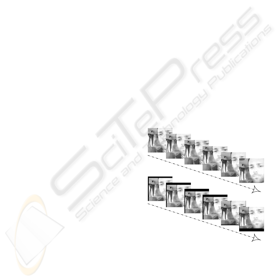
Therefore, the image stabilization in a video-stream
is needed (see Fig. 1). The significant object is al-
ways in the same position in the screen.
We distinguish between two types of movements
with the camera:
Weak shaking (app. ±10° variation in the hori-
zontal and vertical directions and/or some
small units of Hertz)
Strong shaking (more then ±10° variation in the
horizontal and vertical directions and/or tens
of Hertz).
S
equenc
e of i
m
ages
a
fter
s
tabi
l
i
z
at
i
on
S
equenc
e o
f
i
m
ages
bef
or
e s
t
abi
l
i
z
ati
on
Figure 1: Sequence of images before and after the digital
image stabilization.
In the first case, the problem with shaking could
be solved using pure software (digital) image stabili-
zation. On the other hand, strong shaking is imposs-
ible to stabilize only with the software solution, i.e.
some additional hardware is needed. This hardware
can be based either on a servomotor unit or pneu-
matic/hydraulic unit, which are able to compensate
621
Drahansky M. and Orsag F. (2009).
DIGITAL IMAGE STABILIZATION IN A VIDEO-STREAM - Stabilization of (Undesirable) Image Movements in a Video-Stream.
In Proceedings of the Fourth International Conference on Computer Vision Theory and Applications, pages 621-625
DOI: 10.5220/0001803806210625
Copyright
c
SciTePress
the movements of the camera system in the opposite
direction. Such hardware solution exceeds the scope
of this article. Nevertheless, the hardware computing
unit for digital image stabilization is described in the
third chapter. This hardware unit is composed of two
DSP processors with connected FPGAs and
SDRAMs. The purpose of this unit is to ensure suf-
ficient computational power for the digital image
stabilization algorithm, which is introduced in the
following chapter.
2 IMAGE STABILIZATION
ALGORITHMS
Image stabilization algorithms mostly consist of
three main parts: motion estimation, motion smooth-
ing and motion compensation. Main task of the first
block is to estimate a several local motion vectors
and on the basis of these local estimates calculate a
global motion vector. The second block deals with
filtering, integration (respectively), of the estimated
global motion vector. The main purpose of this stage
is to smooth the calculated value and prevent large
and undesirable differences between motion vectors
calculated in past. The last block shifts the acquired
image in inverse direction according to the global
motion vector. This block can take into account
more sophisticated transformations like rotation or
warping.
A lot of various approaches exist nowadays. The
main difference lies in the resultant accuracy of
global motion vector and algorithm used for estima-
tion of local motion vector. We distinguish between
pixel and sub-pixel resolution. Second approach is,
however, complicated and more time consuming
than the previous one because an interpolation me-
thod is needed. So it is rarely used in real-time ap-
plications. Some algorithms consider rotation or
more complex warping in addition to translation.
Table 1 summarizes several basic algorithms and
their parameters. Other algorithms are described e.g.
in (Sachs et al., 2007).
Table 1: Some variants of stabilization algorithms.
Algorithm Accuracy Transformation Ref.
Parametric
Block Matching
sub-pixel translation, rotation
(Vella et
al., 2002)
Gray-Coded Bit
Plane Matching
pixel translation
(Ko et al.,
1999)
Block Matching pixel translation
(Brooks,
2003)
We will concentrate on algorithms that use trans-
lation with pixel accuracy only. In the following
section is described a simply plain matching algo-
rithm and some basic ideas of the stabilization. The
next section will be devoted to one promising algo-
rithm modification of which we used.
2.1 Plain Matching Algorithm
As stated above, the algorithms that deal with stabi-
lization are based on estimation of a motion
represented by a motion vector. The straightforward
solution leads to use of a discrete correlation, cross-
correlation respectively (Brooks, 2003). The discrete
correlation produces a matrix of elements. The ele-
ments with a high correlation (value) correspond to
the locations where a chosen pattern and image
match well. It means that the value of element is a
measure of similarity in relevant point and we can
find locations in an image that are similar to the pat-
tern.
The input is formed by a pattern (in the form of
an image) F and an input image I. It is not necessary
to search the whole image, thus a smaller area
(search window N×N) is defined. At the same time,
this area specifies the maximal shift in vertical and
horizontal direction and is chosen in this manner.
Eq. (1) represents a discrete 2D correlation func-
tion
),( yxIF D
.
∑∑
−=−=
++=
N
Nj
N
Ni
jyixIjiFyxIF ),(),(),(D
(1)
Note that matching according to the first defini-
tion is problematic. Correlation can also be high in
locations where the image intensity is high, even if it
doesn’t match the pattern well. Better performance
can be achieved by a normalized correlation
(Brooks, 2003):
()
∑∑∑∑
∑∑
−=−=−=−=
−=−=
++
++
N
Nj
N
Ni
N
Nj
N
Ni
N
Nj
N
Ni
jiFjyixI
jyixIjiF
2
2
),(),(
),(),(
(2)
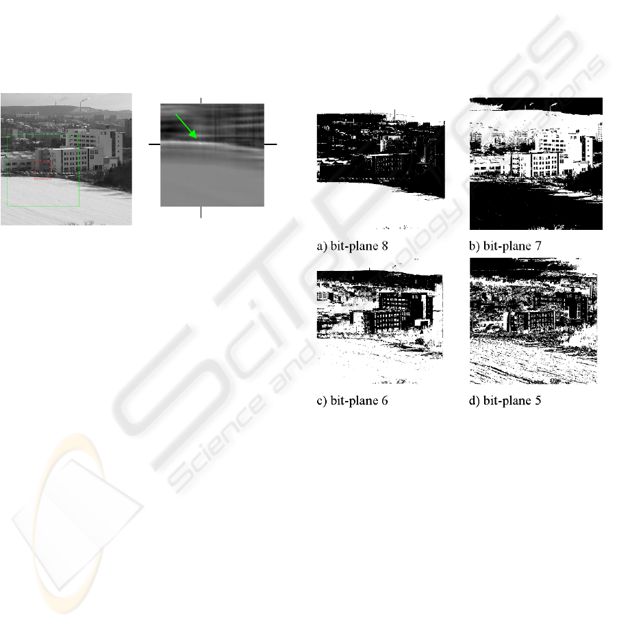
Figure 2 shows an input image, pattern (red
small area) and correlation matrix obtained by the
normalized correlation. We defined the search win-
dow (green big area) and the pattern is searched
within this window. The result matrix has the same
dimensions as the search window (M×M). The pixel
with the maximum value determines position of the
pattern in the search window. Hence, it determines
VISAPP 2009 - International Conference on Computer Vision Theory and Applications
622
position of an area in the search window which is
most similar to the pattern.
The correlation can be calculated in the original
(time) domain according to equation 2 however this
approach is rarely used due to enormous time con-
sumption. Note that for every point of correlation
matrix is necessary to perform 2N×N multiplications
and additions. We can obtain the same result with
lesser effort in the frequency domain (Brooks,
2003).
On the other hand, the Equation (2) appears as
an ideal choice from the hardware processing point
of view. The computation involves only the fixed-
point arithmetic (adders and multipliers) which is
suitable for an FPGA based implementation.
Figure 2: a) Input image with marked search window
(left); b) Correlation matrix obtained by correlation (right).
Stated principle is theoretically ideal solution
when we consider only translation. But in practice
we have to deal with two problems. The first prob-
lem arises from finite resolution of registers and
sampling and it causes existence of several points
with maximal values in the correlation matrix. The
second problem is dependency of results on the
background noise which is present in the input video
signal.
It is necessary (in case of the image stabilization)
to define several independent areas and to calculate
correlation matrices for each of them. We obtain
several local motion vectors and the global motion
vector is calculated as their average or median. This
method prevents errors coming from the correlation
on problematic areas (e.g. with the same intensity).
2.2 Bit Plain Matching Algorithm
Some algorithms, in quest of improving the results,
calculate the correlation from the images passed thru
an edge detector (Ko et al., 1999). This technique
provides certain improvements, but the edge detec-
tors tend to produce many useless pixels and are
sensitive to the image intensity. Last but not least,
the detector introduces additional time-consuming
operation to the phase of processing. As most of
edge detectors are nonlinear systems, it is not possi-
ble to make convolution in the frequency domain.
The noise can be suppressed by ignoring the
least significant bits. Then we can consider only the
higher bits or take only some bit-planes and calcu-
late the correlation using that plane, which consists
only from one and zero values.
Better results can be achieved by gray coded bit
planes. The gray coding allows estimate motion vec-
tor using a single bit-plane by encoding most of the
useful information into a few planes. A small change
in the gray level leads to a small change in the bi-
nary digits representing the intensity. Figure 3 shows
four most significant bit-planes of selected image.
Figure 3: Gray-coded bit planes of image from Fig. 2.
Bit plane matching algorithm does not use corre-
lation, as defined above, and defines a new, but very
similar, operator (see Equation (3)) that has to be
minimized. Note that, in the previous task, we deal
with maximization. In fact, it is the definition of
correlation where the multiplication operator is re-
placed by the binary operator – exclusive or.
∑∑
−=−=
++⊕=
N
Nj
N
Ni
jyixIjiFyxE ),(),(),(
(3)
This error operator is calculated by minimizing
the resulting local motion vector. Several (typically
four) local motion vectors from each area along with
the previous global motion vector are passed through
DIGITAL IMAGE STABILIZATION IN A VIDEO-STREAM - Stabilization of (Undesirable) Image Movements in a
Video-Stream
623
a median operator to produce the current global mo-
tion vector estimate.
Then, the global motion estimate can be option-
ally passed through a filter that is tuned in order to
preserve intentional camera motion while removing
the undesirable high frequency motion.
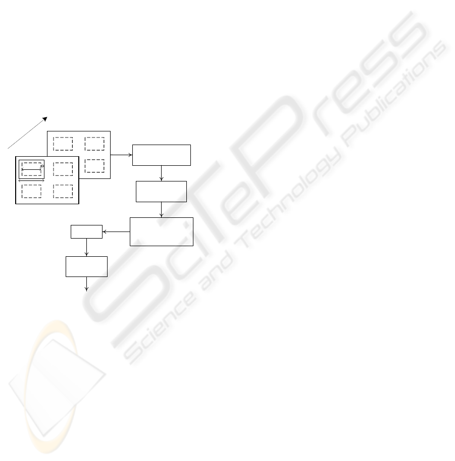
The final filtered motion estimate is used then
for shifting the current frame by an integer number
of pixels in the opposite direction of the motion. The
whole system is depicted at Figure 4.
2.3 Proposed Solution
The method described in the previous section uses
only one bit plane to estimate the local motion vec-
tor. In order to improve the estimation of the local
motion vector, we experimentally determined that at
least two bit planes are suitable to increase the relia-
bility of estimation.
Current Frame
W
M
P
Past Frame
T
i
m
e
Preprocessing –
Gray-Coded Bit
Plane
Four Region
Motion Estimation
Global Motion
Estimation Using
Median
IN
Integration
Motion
Compensation
(Pixel)
OUT
Figure 4: Scheme of digital image stabilization.
The next improvement lies in the usage of more
than one maximum. This solution will be stable in
the situations, where the edges have very low con-
trast. Now we are trying to use 5 highest maximum
peaks in the searching area. This could be taken into
the account by the computation of global motion
vector.
The last optimization is to split the image to
some predefined number of regions, in which the
maximums are searched. Robustness of such algo-
rithm increases using this optimization.
Our intention is to reduce the computational de-
mands on processor (DSP – see next chapter) that
the standalone unit without cooling could operate,
and our algorithm should be stable also in regions,
where nearly no clear edges exist, e.g. desert, sea
etc.
3 HARDWARE SOLUTION
Algorithms mentioned in the previous chapter can be
easily implemented in a common PC. Our goal,
however, is to design a standalone solution to the
image stabilization, which has to fulfill defined spe-
cifications. Result of our aims should be a device
able to stabilize an input video stream and send the
stabilized stream to an output.
The specifications that must be fulfilled are de-
fined as follows:
• Size of the final board must not exceed 100
× 120 mm.
• Height of the final product must be lower
or equal to 12 mm.
• The board should contain four layers not
exceeding total width of 1.5 mm.
• The final product must be able to operate
under military conditions, e.g. temperature
of operation ranges from -40° to 85° C.
The board consists of input/output connectors,
persistent storage units, processing units, microcon-
troller, and video processing unit.
The connectors serve simply for the video input
and output purposes. The persistent storage is in a
form of a FLASH memory containing software,
which is booted after reset of the board. There is a
slot for an SD card too, which enables user to up-
grade the software. A new version of the software is
uploaded to the FLASH memory automatically
when an SD card is present in the slot. The micro-
controller provides means of communications be-
tween the individual components (FLASH memory
– SD Card, FLASH memory – FPGA etc.). The vid-
eo processing unit consists of an encoder and decod-
er determined to encode/decode the video stream.
The main part of the board is the processing unit.
For this task we decided to use a combination of an
FPGA and digital signal processor (FPGA-DSP
combination) as the engine of the board.
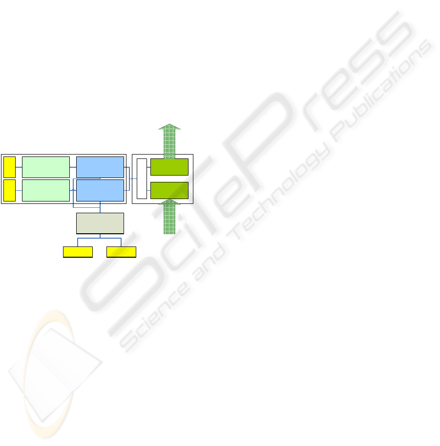
Since the board must count on future upgrades, it
contains an independent pair of the FPGA-DSP
combination (see Figure 5) working in parallel. Each
FPGA-DSP combination has its own memory bank
to avoid memory stalls and shared memory issues.
This way there is one FPGA-DSP pair for the image
stabilization and the other FGPA-DSP pair for the
VISAPP 2009 - International Conference on Computer Vision Theory and Applications
624
future upgrades (e.g. for an object tracking). Each
module can operate separately, is independent (even
though they can use each other’s results), and can be
omitted from the final design, which makes the
board very variable.
The first processing unit serves for the purposes
of the image stabilization. It can read frames from
the input video stream, store it in its memory and
process it. The result frame can be sent to the output
video stream. The second processing unit doesn’t
need to be included on the board. When it is present
on the board however, it can communicate directly
with the first module. It can read frames of the input
video stream and send them to the output video
stream too. When both units are functional and
working, the output stream is given by the second
unit. Each module can be turned off so that each
stage of the video stream processing can be easily
bypassed (it can be useful in some situations to see
the original, unprocessed input video stream).
DSP unit 1
DSP unit 2
SDRAM 1SDRAM 2
FPGA unit 1
FPGA unit 2 Video input
Video output
Interface
Microcontroller
SD cardFlash
Figure 5: Proposed design of the board for the image stabi-
lization.
This solution is a compromise between the
hardware specifications, given constraints and algo-
rithm requirements. The combination of an FPGA
and DSP allows us to spread tasks given by the algo-
rithm between both – the processor and gate array.
Hence, FPGA can perform some general operations
(preliminary steps of the algorithm), whereas the
DSP can focus itself on the calculations (e.g. Fast
Fourier Transform).
4 CONCLUSIONS
We have a standalone unit with two DSP processors
ready to realize digital image stabilization. One
backup DSP-FPGA pair is ready for future use, e.g.
for the task of an object tracking.
At the moment, three parallel ways for the algo-
rithm of image stabilization are used. We try to use
common algorithms for this task, but with our opti-
mizations and improvements to ensure strong ro-
bustness.
The future work is to load the optimized paralle-
lized program to the hardware unit. Testing and fur-
ther optimizations, especially in parallelism, will be
performed soon. Of course, further improvements
will be needed, e.g. for different regions of usage
(e.g. arctic ice region, windy areas etc.). In the fu-
ture, we want to try to implement the image stabili-
zation on another DSP platform which does not use
a fixed point as our contemporary solution.
ACKNOWLEDGEMENTS
This research has been done under the support of the
grant “Security-Oriented Research in Information
Technology”, MSM0021630528 (CZ).
REFERENCES
A.C. Brooks, “Real-Time Digital Image Stabilization”, EE
420 Image Processing Computer Project Final Paper,
EED Northwestern University, USA, March 2003, p.
10.
D. Sachs, S. Nasiri, D. Goehl, “Image Stabilization Tech-
nology Overview”, InvenSense Inc., USA, 2007, p. 18.
S.J. Ko, S.H. Lee, S.W. Jeon, “Fast Digital Image Stabi-
lizer Based on Gray-Coded Bit-Plane Matching”,
IEEE, USA, 1999, pp. 90-91, ISBN 0-7803-5123-1.
F. Vella, A. Castorina, M. Mancuso, G. Messina, “Robust
Digital Image Stabilization Algorithm Using Block
Motion Vectors”, IEEE, USA, 2002, pp. 234-235,
ISBN 0-7803-7300-6.
DIGITAL IMAGE STABILIZATION IN A VIDEO-STREAM - Stabilization of (Undesirable) Image Movements in a
Video-Stream
625
