
ROBUST OCCLUSION HANDLING WITH MULTIPLE
CAMERAS USING A HOMOGRAPHY CONSTRAINT
Anastasios L. Kesidis and Dimitrios I. Kosmopoulos
Computational Intelligence Laboratory, Institute of Informatics and Telecomunications
National Center for Scientific Research “Demokritos”, GR-153 10 Agia Paraskevi, Athens, Greece
Keywords: Multiple views, Occlusions, Homography.
Abstract: The problem of human detection in crowded scenes where people may occlude each other has been tackled
recently using the planar homography constraint in a multiple view framework. The foreground objects
detected in each view are projected on a common plane in an accumulated fashion and then the maxima of
this accumulation are matched to the moving targets. However the superposition of foreground objects
projections on a common plane may create artifacts which can seriously disorientate a human detector by
creating false positives. In this work we present a method which eliminates those artifacts by using only
geometrical information thus contributing to robust human detection for multiple views. The presented
experimental results validate the proposed approach.
1 INTRODUCTION
The problem of detecting moving targets in crowded
scenes is one of the most challenging topics in
computer vision mainly due to occlusions. The
employment of target models for tracking using a
single camera has serious difficulties in cases that
the target is partially or fully occluded (e.g.,
(Makris, 2007). Therefore several researchers used
multiple cameras to compensate that problem.
Having multiple overlapping views increases the
possibility that the target is visible or less occluded
in one of those views.
Regarding the target matching in overlapping
views, there are several taxonomies of the related
methods according to the used features and
according to the requirement for camera calibration.
A popular approach is to consider the targets as
regions and then to use the region features for
matching in multiple views. Color is a popular
feature and is modeled through color histograms,
e.g., (Krumm, 2000) or Gaussian color models, e.g.,
(Mittal, 2003). However, targets having similar
colors may be poorly matched. Different viewpoints
and lighting variations may cause the same target to
be observed with different colors in different
cameras. Inhomogeneous color may also cause
problems if the same target exposes different colors
in different cameras.
Several approaches use geometrical constraints,
which may require either camera calibration or a
homography constraint based on the ground plane.
The 3D methods transform all points, e.g., target
centroids into the common 3D coordinate system
and perform matching based on the proximity of
those points, e.g., (Kelly, 1995). Alternatively the
epipolar constraint is employed, using only the
relative pose of the cameras, e.g., (Cai, 1999).
Several recent works exploit the fact that the
targets move on a common plane, especially for
indoor scenes, e.g., (Eshel, 2008), (Hu, 2006),
(Khan, 2006), and (Khan, 2007). The approach that
is commonly followed in such a framework can be
roughly described by the following stages:
a) Background subtraction to get moving objects.
b) Employment of homography constraint to
project the foreground regions on a common plane.
c) Processing of the projected data to extract the
moving targets - the focus of our work.
d) Optionally additional processing for matching
the targets either using templates or color models,
which will not be further examined here.
Background subtraction includes modeling each
pixel’s color, e.g., as a Gaussian Mixture. Whatever
deviates from the model is considered foreground. A
review can be found in (Hall, 2005).
The projection is based on the results from
560
L. Kesidis A. and I. Kosmopoulos D. (2009).
ROBUST OCCLUSION HANDLING WITH MULTIPLE CAMERAS USING A HOMOGRAPHY CONSTRAINT.
In Proceedings of the Fourth International Conference on Computer Vision Theory and Applications, pages 560-565
DOI: 10.5220/0001804605600565
Copyright
c
SciTePress
previous stage. It calculates offline the
transformation of a reference ground plane to the
plane of each camera through a homography matrix.
It then projects each pixel classified as foreground in
each view in the reference plane, e.g., (Khan, 2006).
In (Khan, 2007) the same idea is extended for
multiple parallel planes to obtain 3D shape of the
monitored targets. In (Eshel, 2008) three planes and
the correlation of intensity values for head detection
are used.
As soon as the projection on the common plane
takes place the detection of moving targets starts
(stage c). In (Khan, 2006) the projected foreground
pixels create a synergy map in an accumulator
fashion and the maxima correspond to ground target
position. This method provided many false positives,
due to intersection of the projected silhouettes that
create undesired maxima. We propose a method for
eliminating these false positives using only
geometrical information, thus avoiding the error-
prone color modeling.
In the next section we present the principles for
the accumulator calculation and the problems that
arise. In section 3 we present how we overcome
these issues. In section 4 we present experimental
results and section 5 concludes this paper.
2 GROUND PLANE
ACCUMULATOR
In this section we calculate the accumulator, we
show the problems in approaches based on (Khan,
2006) and we introduce our solution using only
geometric information.
The planar homographies are geometric entities
that associate points on different planes. Assume
that a point on the ground plane is expressed as
()
T
1,,P ΥΧ=
π
and that the coordinates of this point
on the camera plane are
()
T
1,,P yx
c
=
. The
homography
H
is a 3x3 matrix which relates
π
P and
c
P as follows:
c
PHP =
π
(1)
The homography matrix can be calculated using a
known pattern, visible from all cameras. From the
previous equation we construct the accumulator by
simply projecting on the ground plane the
foreground pixels
()
T
1,, yx
in each camera. The
maxima of this array correspond to ground point
positions of the viewed target on the ground plane,
that is, the position where the feet touch the ground.
The maxima are filtered out by applying a threshold
that equals the number of cameras in use. To extract
the feet blobs, connected component analysis is
performed on the filtered ground points. People are
detected by grouping feet blobs belonging to the
same person into clusters. In the following analysis,
the term “object” refers to a collection of blobs in
the ground plane that belong to the same person.
The main aim of the proposed method is to
efficiently maintain the information contained in the
attributes of the blobs (size, orientation,
connectivity) in order to group them into objects so
that each object correctly identifies the location of a
person in the ground plane. The object position can
then be back projected into the camera views in
order to extract information (e.g. the vertical axis) of
the person(s) position in the original data.
Effective target extraction depends on the
following issues:
1) Blob assignment. Usually an object consists of
one or two blobs depending on the walking cycle.
Thus, the number of blobs that constitute an object is
constantly changing. Therefore, adding or removing
a blob from an object depends on its position on the
plane as well as on the geometrical properties of the
object itself.
2) Blob size. The connected component analysis that
is applied to the accumulator may result to large
blobs as a result of morphological merging of two or
more maxima areas. Figure 1 depicts an example.
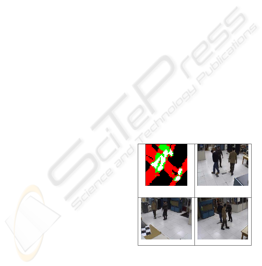
Figure 1: Merged blobs in the ground plane due to
connected component analysis. The white areas
correspond to the maxima.
3) Pseudo-blobs. The projection of each person's
silhouette in the image plane corresponds to a
"shadow" in the ground plane. The homography
Ground plane
Camera 1
Camera 2
Camera 3
ROBUST OCCLUSION HANDLING WITH MULTIPLE CAMERAS USING A HOMOGRAPHY CONSTRAINT
561
transformation may produce maxima at points of
multiple shadow co-occurrences. In Figure 2 blobs 2
and 3 denotes two such cases.
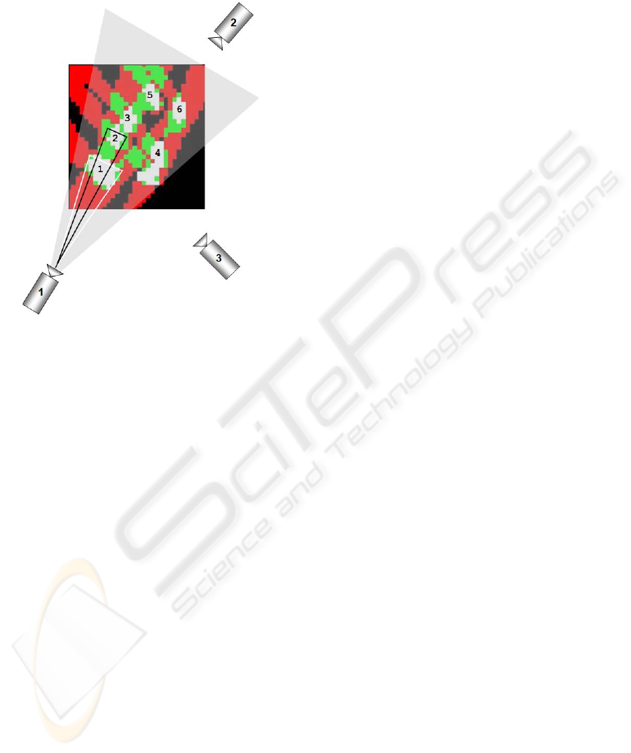
Figure 2: Magnified section of the accumulator displaying
the maxima resulting from three persons for the given
camera configuration. Blobs 1,4,5,6 correspond to
humans, while blobs 2, 3 are false positives.
The following section presents our method
regarding the above issues.
3 TARGET DETECTION
3.1 Object Determination
Let us suppose there are
L
n objects in the ground
plane from the previous frame and that each object
l
M , l=1…
L
n , is represented as an Gaussian
mixture model (GMM) where the probability density
function is composed of a mixture of m component
densities {λ
1
,…, λ
m
}. There are
)( l
m components in
the l-th object and each one corresponds to a
Gaussian distribution that describes the statistical
properties of a maxima subset in the accumulator
array. Let also
B
n denote the number of blobs in the
ground plane that we want to group into objects and
let
j
s denote the number of points in blob
j
B
where j=1…
B
n . For any point
ji
B∈x the
probability that it belongs to object
l
M is given by
()
()
()
()
()
()
∑
=
=
l
m
j
l
j
l
j
ii
Pplp
1
;
λλ
|xx
(2)
Typically, the weight P(λ
j
) of each mixture and the
parameters
(
)
j
p
λ
|x
~
(
)
jj
N Σ,μ
for each component
are unknown and a parameter estimation
methodology is applied to determine them. In the
proposed approach the Expectation Maximization
(EM) algorithm is used to obtain maximum
likelihood estimates of the parameters in the GMM.
For each point
ji
B∈x
an object candidate
i
c is
calculated as
(
)()
⎪
⎩
⎪
⎨
⎧
>
=
otherwise0
;if;argmax
pii
l
i
tlplp
c
xx
(3)
Threshold
p
t defines a minimum allowed
probability that some blob j belongs to some object
l. Let the stochastic vector
j
f hold the probability
mass function
(
)
lc
i
=
Pr regarding the j-th blob, for
all points in the blob. If
j
l
ˆ
=argmax(
j
f
) then the
blob
j
B
is added to object
j
l
M
ˆ
:
()
0andmaxif >>
⎭
⎬
⎫
⎩
⎨
⎧
∪=
jcjj
ll
ltBMM
jj
ˆ
f
ˆˆ
(4)
Threshold
c
t designates a minimum proportion of
points in blob
j
B
that must be closer to some object
j
l
M
ˆ
in order to assign the whole blob to this object.
In case where any of the two conditions in (4) is not
fulfilled, a new object is created that holds only
blob
j
B
, that is
j
l
BM
j
=
ˆ
where
j
l
ˆ
= 1+
L
n
(5)
This case arises in isolated blobs, a typical situation
when a new person enters the scene. The creation of
a new object is affected by thresholds
p
t and
c
t
both of which are application related.
The above process is repeated for all the blobs in
the ground plane. Finally, any objects that have no
blobs assigned to them are eliminated. Otherwise,
the GMM of each object
l
M is recalculated based
on the newly assigned blob points.
3.2 Blob Size Normalization
Connected component analysis on the maxima of the
accumulator may result to merged components
(blobs) that actually correspond to different objects,
as shown in Figure 1. In this case, where the blob
size exceeds a predefined threshold
s
t , a splitting
process is applied before the object determination
VISAPP 2009 - International Conference on Computer Vision Theory and Applications
562

phase in order to break down the blob into several
smaller ones that may then be assimilated by
different objects or even rejected as pseudo-blobs.
In order to split a blob
j
B into two parts a
Gaussian mixture model (GMM) is used with two
components {λ
1
, λ
2
}. Let
k
μ and
k
Σ denote the
mean and variance of component λ
k
. Blob
j
B is
replaced by two blobs
(1)j
B
and
(2)j
B
and each
point
ji
B∈x
is assigned to
{
}
kdBB
ijikj
=∈= thatsuch
)(
x
(6)
where
i
d denotes the closer component according to
the Mahalanobis distance. The process may be
repeated until
j
B is replaced by two or more blobs
with sizes less than threshold
s
t .
3.3 Pseudo-blob Removal
In crowded scenes where people are standing close
to each other, the projection of each person's
silhouette into the accumulator using the
homography may cause the appearance of pseudo-
blobs as a result of overlapping shadows in the
ground plane view. It can be noticed that each
shadow in the ground plane corresponds to a person
in the original image viewed from a specific camera.
Moreover, there are three shadows for each person
each one starting from the blob(s) that correspond to
the feet. The intersection region of any three
shadows forms a potential pseudo-blob area. Figure
2 depicts a ground plane example that corresponds
to three persons standing in a scene viewed by three
cameras (see also Figure 3 , left column). The white
areas correspond to accumulator values equal to 3. It
can be seen that co-linear arrangement of camera
sources with two or more feet blobs results to mutual
shadows overlapping, like blobs 1 and 5. However,
there are cases like blobs 2 and 3 where shadows
from blobs 1, 4 and 5 overlap in the middle region
resulting to pseudo-blobs 2 and 3.
We propose a method for removing these
artificial blobs by examining the visibility of each
blob from the cameras. Specifically, we check if for
any blob
j
B
there are other blobs that conceal it
partially or fully when viewed from the camera. The
visibility of blobs can be effectively computed in a
straightforward fashion by back transforming all
blobs from the ground plane to the camera views.
Rather than comparing blob-to-camera vicinity in
ground plane polar coordinates, the transformed blob
pixels are compared according to their vertical
position in each camera's Cartesian coordinate
system (Figure 3, right column). Specifically, let
j
B
~
denote the transformed pixels of the
j-th blob in the
k-th camera view. Let
{
}
maxmin
...
jjjx
xx=r
denote
the set of x-coordinates that blob
j
B
~
occupies in the
current camera view. Similarly, let
maxj
y
=
{
}
jyj
Bx
~
∈
)(
max denote the largest of all y-
coordinate values. The blob with the greatest
maxj
y
coordinate at x among all blobs with x in their range
of x-coordinates, is given by
(
)
{
}
jxjj
j
xByxy r
~
, ∈∀= :argmax
max
(7)
The visibility of blob
j
B
~
from the camera is
()
∑
∈
=
jx
x
jx
j
xyv
r
r
1
such that
()
jxy =
(8)
where
x denotes the cardinality of set x . The
value of
j
v
ranges from 0 (no visible at all) up to 1
(fully visible). The above process is repeated for the
rest of the cameras. An application related threshold
v
t can be defined to binarize the decision making.
(
)
(
)
∑
>=
v
c
j
j
tvv
~
for all the cameras c
(9)
For each blob,
j
v
~
is an integer value that ranges
from 0 up to the overall number of cameras in use.
For zero value of
j
v
~
, blob
j
B
~
can be rejected as
pseudo-blob since it is not visible (in a certain
degree, controlled by
v
t ) from any camera. In this
case, this blob does not participate in the object
determination process described in section 3.1. In
Figure 3 the left column depicts the three camera
views for the same frame as in Figure 2. The right
column depicts a zoomed area of the feet for the
corresponding foreground silhouettes. Each
horizontal line segment corresponds to the range
jx
r
of a blob
j
B
~
. Thus, for any x offset, the visible blob
is the one closer to the bottom of the image.
4 EXPERIMENTAL RESULTS
The proposed method has been tested in a
surveillance system installed in our lab that consists
ROBUST OCCLUSION HANDLING WITH MULTIPLE CAMERAS USING A HOMOGRAPHY CONSTRAINT
563
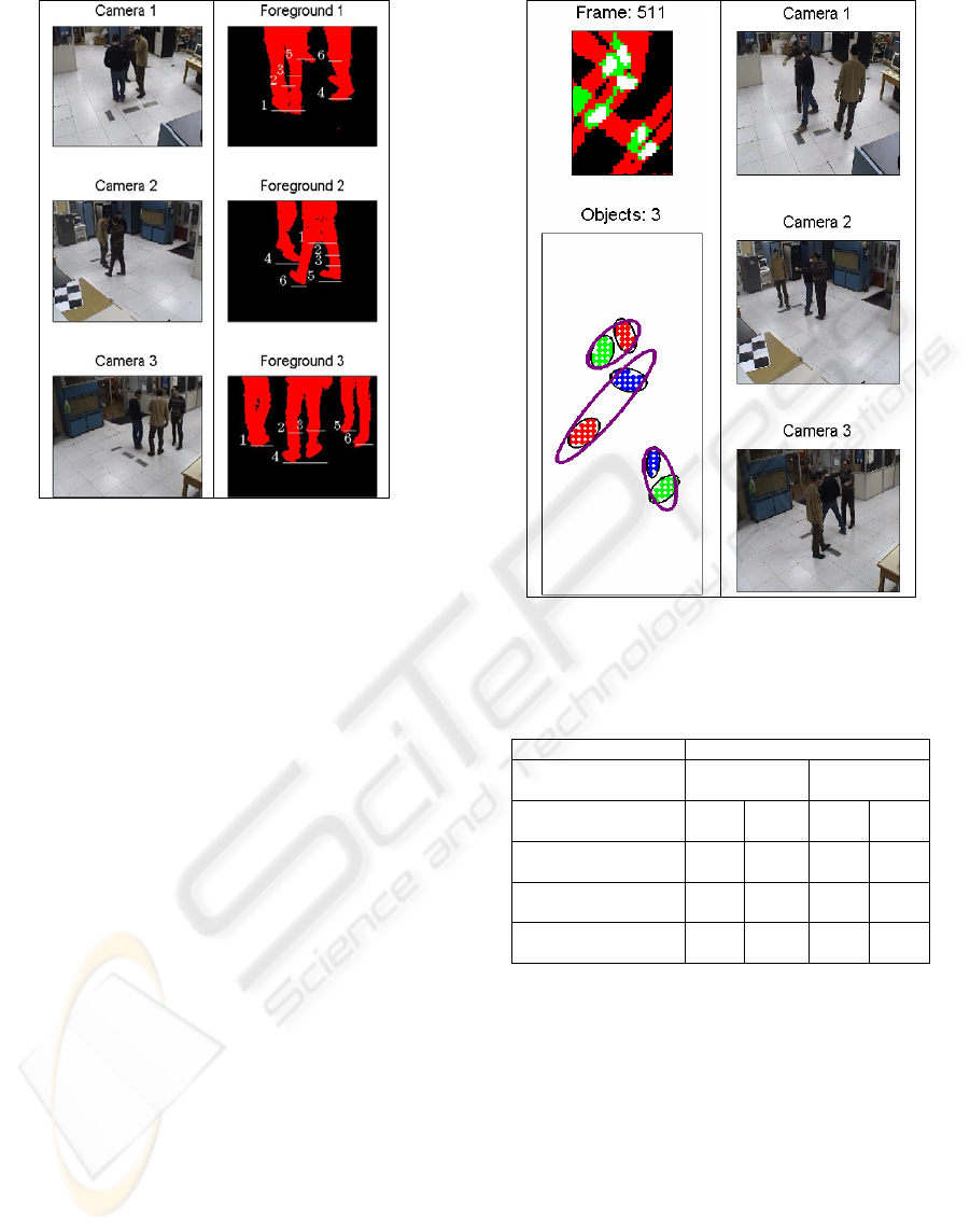
Figure 3: Left column: the three camera views. Right
column: the front view of each blob back-projected to
each view, superimposed to foreground masks. It is clear
that blobs corresponding to real targets are closer to the
bottom of the image in at least one view for some x
coordinates, while this does not happen for the false
positives.
of three cameras as shown in Fig. 2. Cameras 1 and
2 have been deliberately located in a facing position
in order to better simulate a real world situation
where the optimum equidistant installation of 120
degrees between cameras is barely achieved due to
space limitations. To evaluate our method we have
used a sequence of 1650 video frames from each one
of the three cameras that depict a varying number of
persons entering, walking and exiting the scene.
Table 1 summarizes the detected false positives (FP)
when comparing the original (Khan, 2006) and the
proposed method. The results show that for 2 and 3
persons in the scene (when actually overlapping may
occur in the ground plane) the proposed method
significantly decreases the number of false positives
in the blob detection. Indeed, due to the blob
normalization and pseudo-blob removal processes
the proposed method successfully ignores blobs that
do not actually belong to any person in the scene.
Figure 4 depicts the proposed method's efficiency in
a complex and person 1 makes a large stride.As a
result his right foot is clearly closer to the feet that
correspond to person 2. However, in order to keep
its feet (blobs 1 and 3) together. The contours in the
lower left subplot denote the identified objects and
their centre corresponds to the person's vertical axis.
1
2
3
4
Object 1
Object 2
Object 3
1
2
3
4
5
6
5
6
Figure 4: Object determination consistency. The persons
are correctly identified by their blobs (lower left drawing )
even when person's 1 right foot is closer to object 2.
Table 1: False positives for ground plane blobs.
Persons in frame False Positives
Original
method
Proposed
method
1
(148 frames)
0 0% 0 0%
2
(421 frames)
12 2.8% 8 1.9%
3
(1053 frames)
83 7.3% 26 2.4%
Overall
(1622) frames
95 5.8% 34 2.0%
These points are back projected in the 3 cameras
views in order to denote the intersection point of
each person with the ground plane. Figure 5 depicts
an even more complicated case, a few frames later,
where both blob normalization and pseudo-blob
removal are applied. Initially there are 4 blobs in the
ground plane, of which, blobs 1 and 2 exceed the
threshold
s
t =30 (upper left drawing). After the blob
size normalization process is applied, the first one is
divided into blob 1 and 2 as shown in the lower left
drawing of Figure 5, while the other one is replaced
by blobs 3 to 6. However, blobs 2, 4 and 5 are
identified as pseudo-blobs since their visibility from
the cameras is not sufficient enough (less than
VISAPP 2009 - International Conference on Computer Vision Theory and Applications
564
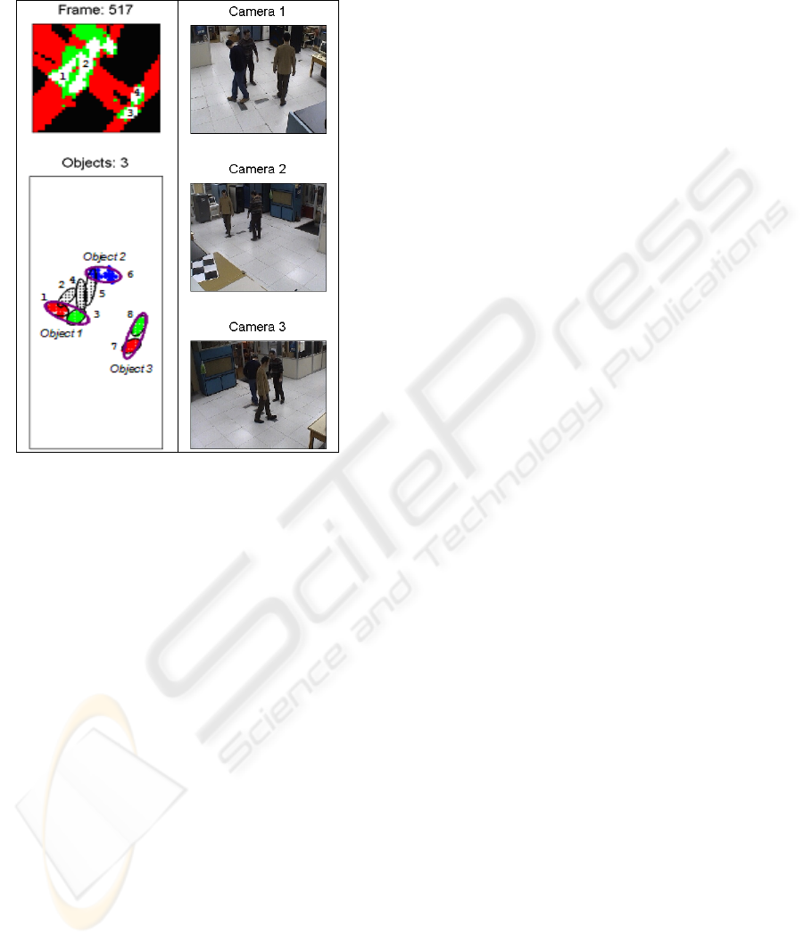
v
t =0.5). The object determination process ignores
them and correctly determines the three objects
consisting by blobs (1,3), (6) and (7,8), respectively.
Figure 5: Blob normalization and pseudo-blob removal for
large blobs. After dividing the large blobs into smaller
ones, only those that are sufficiently visible from the
cameras participate in the object determination process.
5 CONCLUSIONS
In this paper we addressed the problem of detecting
humans in crowded scenes where several occlusions
take place. We have used only geometrical
information given the foreground silhouettes. We
have identified the main sources of errors when
detecting humans based on the homography
constraint. Namely these are the merging – splitting
of accumulator corresponding to maxima and the
appearance of maxima not corresponding to humans.
We have set the criteria for the split operation and
we have shown how to identify and reject the false
positives. The presented experimental results have
verified the proposed approach. Generally if the feet
are partially visible from one camera and detected as
foreground we are able to detect the presence of a
human and not to reject the associated maximum in
the map as false positive. Our next steps include
integrating our detection scheme with a tracker for
consistent monitoring of humans in crowd.
REFERENCES
Makris A., Kosmopoulos D., Perantonis S, Theodoridis S.,
2007. A Hierarchical Feature Fusion Framework for
Adaptive Visual Tracking. In
IEEE Int. Conf. on
Image Processing
, ICIP07, vol 6, pp 289-292.
Eshel, R., Moses, Y., 2008. Homography based multiple
camera detection and tracking of people in a dense
crowd. In
IEEE Conf. on Computer Vision and Pattern
Recognition
, pp. 1-8.
Hu W. , Hu M. , Zhou X. , Tan T., Lou J., Maybank S.,
2006. Principal axis based correspondence between
multiple cameras for people tracking. In
IEEE
Transactions on Pattern Analysis and Machine
Intelligence
, vol. 28, no 4, pp. 663–671.
Hall D., Nascimento J., Ribeiro P., Andrade E., Moreno
P., Pesnel S., List T., Emonet R., Fisher R. B., Victor
J. S., Crowley J. L., 2005. Comparison of target
detection algorithms using adaptive background
models. In
Int. Conf. on Computer Vision, pp. 113–
120.
Khan, S.M., Shah, M., 2006. A multiview approach to
tracking people in crowded scenes using a planar
homography constraint. In
Europ. Conf. on Computer
Vision
, vol. 4, pp. 133–146.
Khan S.M., Yan P., Shah M., 2007. A homographic
framework for the fusion of multi-view silhouettes. In
Int. Conf. on Computer Vision pp. 1-8.
Krumm J., Harris S., Meyers B., Brumitt B., Hale M.,
Shafer S., 2000. Multi-camera multi-person tracking
for easy living. In
3rd IEEE Int. Workshop on Visual
Surveillance
, pp. 3-10.
Mittal A., Davis L. S., 2003. M2tracker: A multi-view
approach to segmenting and tracking people in a
cluttered scene. In
Int. J. Computer Vision, vol. 51, no
3, pp. 189–203.
Kelly P. H., Katkere A., Kuramura D. Y., Moezzi S.,
Chatterjee S., 1995. An architecture for multiple
perspective interactive video. In
3rd ACM Int. Conf.
on Multimedia
, pp. 201–212.
Cai Q., Aggarwal J., 1999. Tracking human motion in
structured environments using a distributed-camera
system. In
IEEE Trans. on Pattern Analysis and
Machine Intelligence
, vol. 21, no 11, pp. 1241–1247.
ROBUST OCCLUSION HANDLING WITH MULTIPLE CAMERAS USING A HOMOGRAPHY CONSTRAINT
565
