
BREADER:
A MODULAR FRAMEWORK FOR VISION
RECOGNITION OF MATHEMATICAL-LOGICAL STRUCTURES
Celia Salmim Rafael
ESTM, IPLeiria, Peniche, Portugal
Jorge Simao
DCC-Faculty of Sciences-University of Porto, Center for the Science of Computation
Cognition and Complexity, Porto, Portugal
Keywords:
Pattern Analysis and Recognition, Geometry Visual Recognition, Mathematical Expression Visual Recogni-
tion, Symbol and Structure Recognition.
Abstract:
We describe a system that uses image processing and computer vision techniques to discover and recognize
mathematical, logical, geometric, and other structures and symbols from bit-map images. The system uses
a modular architecture to allow easy incorporation of new kinds of object recognizers. The systems uses
a “blackboard” data-structure to retain the list of objects that have been recognized. Particular object rec-
ognizers check this list to discover new objects. Initially, objects are simple pixel clusters resulting from
image-processing and segmentation operations. First-level object recognizers include symbol/character rec-
ognizers and basic geometric elements. Higher-level object recognizers collect lower-level objects and build
more complex objects. This includes mathematical-logical expressions, and complex geometric elements such
as polylines, graphs, and others. The recognized objects and structures can be exported to a variety of vector
graphic languages and type-setting systems, such as SVG and L
A
T
E
X.
1 INTRODUCTION
We describe a system that uses image processing and
computer vision techniques to discover and recognize
mathematical, logical, geometric, and other structures
and symbols from bit-map images. The system uses
a modular architecture to allow easy incorporation of
new kinds of object recognizers. The system uses a
“blackboard” data-structure to retain the list of ob-
jects that have been recognized. Particular object rec-
ognizers check this list to discover new objects (Nii,
1986). Initially, objects are simple pixel clusters re-
sulting from image-processing and segmentation op-
erations. First-level object recognizers include sym-
bol/character recognizers and basic geometric ele-
ments. Higher-level object recognizers collect lower-
level objects and built more complex objects. This
includes mathematical-logical expressions, and com-
plex geometric elements such as polylines, graphs,
and others.
The recognized objects and structures can be ex-
ported to a variety of vector graphic languages and
type-setting systems, such as SVG and L
A
T
E
X. The
selection of recognition operations performed by the
system can be selectable according to the application
domain (e.g. mathematics, logics, geometry construc-
tion, program code, etc.). The systems also allow in-
teraction with the user, including selection of different
domains and/or recognizers in different regions of the
same image.
Symbol recognition relies on the computation of
simple but highly predictive cues, stored in a data-
base. Experimented cues include spectral (Fourier-
like) feature vector, and other cues related to symme-
try and topology of symbols. A simple classification
algorithm, sequential or multi-level nearest-neighbor,
is used to compare extracted features with symbol fea-
ture vectors stored in a data-base.
A graph relating symbols positions and topolog-
ical relations is also built, to allow the construction
of high-order objects coding expressions. The edges
of the topological graph are also stored in the “black-
board” data-structure for simple integration with the
rest of the system. Mathematical-logicals structures
are built by recursive application of composition rules
on object and topological relations.
249
Salmim Rafael C. and Simao J. (2009).
BREADER: A MODULAR FRAMEWORK FOR VISION RECOGNITION OF MATHEMATICAL-LOGICAL STRUCTURES.
In Proceedings of the Fourth International Conference on Computer Vision Theory and Applications, pages 249-255
DOI: 10.5220/0001808702490255
Copyright
c
SciTePress
The recognized object structures can be exported
to a variety of vector graphic languages and type-
setting systems, such as SVG. The recognition and
image processing pipeline is highly configurable and
can rely on an interactive GUI. This allows parame-
ters to be set and object exporting options to be se-
lected. The system is built in a modular way such that
adding new types of object recognizers or expression
composition rules is simple. We have been evaluating
the system by testing a variety of images, such as spe-
cially prepared images, and photography images from
classroom boards. The system current version is im-
plementation in R, with plan to be reimplemented in
JAVA.
2 SYSTEM OVERVIEW
The goal of our system is to map raster-images (bit-
maps in some format), containing semantic informa-
tion in mathematical, geometrical, or diagramatic no-
tations, to a vector graphics or other symbolic repre-
sentations. For example, a bit-map image with a line
and a circle, should be mapped to a vector graphics
representation that includes a parametric object rep-
resenting the line, and another parametric object rep-
resenting the circle. Likewise, symbols should be rep-
resented as text like representation (as in OCR), and
mathematical formulas should have a compact rep-
resentation (e.g. expression tree). To make the sys-
tem open, we want the vector representation to be ex-
ported to a variety of formats. Moreover, we want the
system to be modular to allow easy incorporation of
new kinds of object recognizers as the system is de-
veloped and new domains are focused.
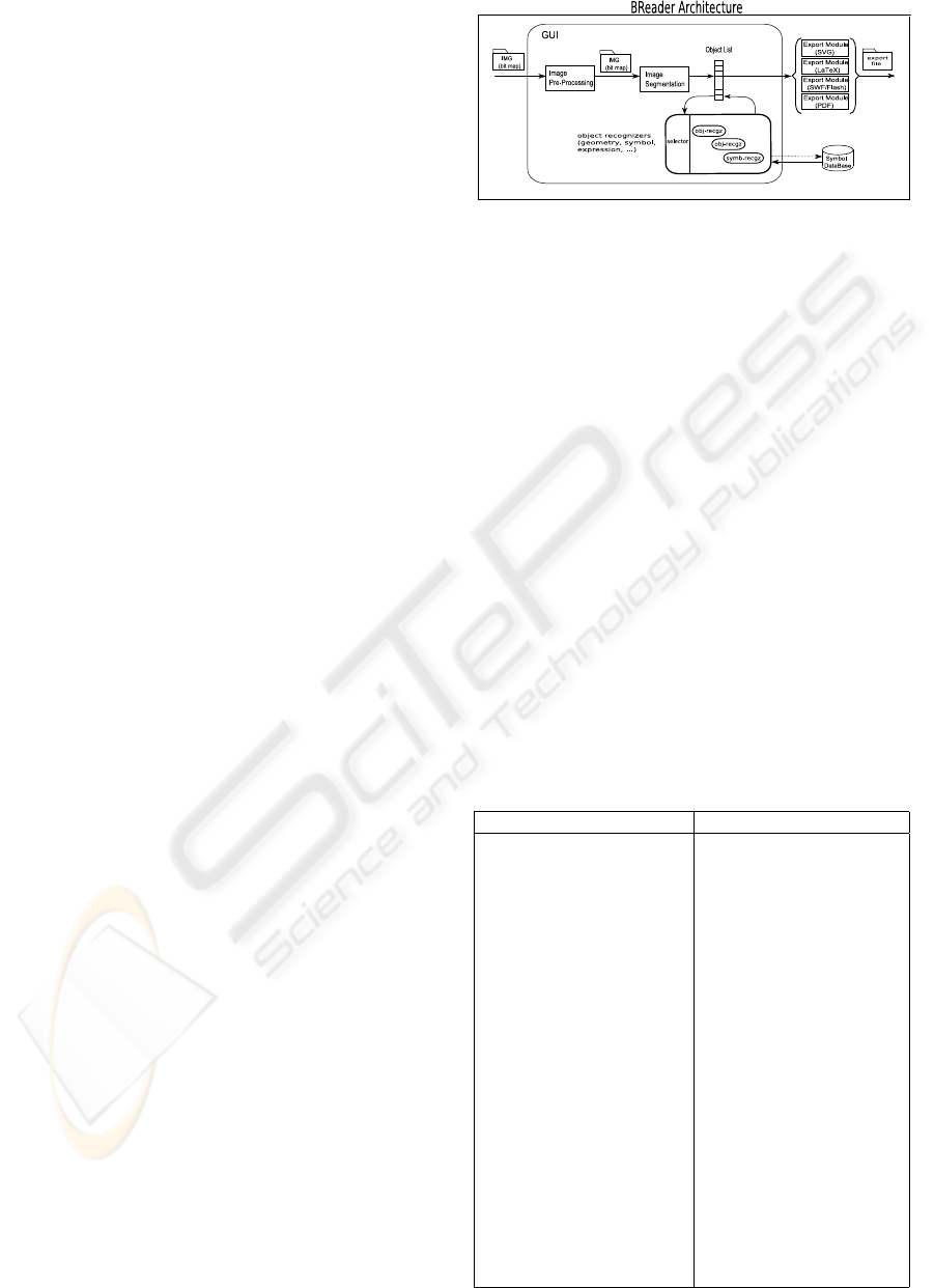
The system uses a ‘blackboard” data-structure and
architecture where a list of objects, designated hereby
lob j, contains all recognized objects so far. Fig-
ure 1 presents a diagrammatic representation of the
proposed system architecture. Initially, raster-images
are fed as input to an image pre-processing module
that prepares the images to further processing. Ad-
ditionally, an image segmentation operation is used
to identify level-0 objects, consisting of pixel clus-
ters, defined as connect or semi-connect line paths
or point sets. This is stored as cluster(lpx) object,
where argument l px is the list of pixel in the clus-
ter. Thus, at an early stage of recognition we have
lob j = {cluster(l px
i
)}.
A set of higher-order object recognizers is then
used to build more complex objects. Some recog-
nizers deal with geometric structures, other deal with
symbol recognition and mathematical-logical expres-
sions building. An intermediate step is to identify
.
.
.
Figure 1: BREADER Architecture as a block diagram.
topological and spatial relations between symbol that
can be used by expression building operations. All
these object recognizers produce as output further
parametrized objects, that are inserted in the object
list lob j. The components objects of a more com-
plex object are usually removed from the list of object
to prevent multiple solution to the recognition pro-
cess. For example, if a circle is recognized in a pixel
cluster and object cluster(l px) is replaced by an ob-
ject circle(c, r). Like-wise, if two clusters are recog-
nized as symbol objects, then objects sym(text
i
) and
sym(text
j
) are introduced in the list of object. Further
processing may recognize the two symbol as part of
a (sub-)expression, and are replaced by an object of
the type expr(op,text
i
,text
j
), where op is the type of
operation.
The final list of objects can be exported to a vari-
ety of file formats for vector graphics and/or typeset-
ting systems. Below, we summarize the list of object
current version of BREADER supports:
Table 1: Summary of objects recognized by the system.
object purpose
bit-map objects
cluster(l px) set of (semi-)connected pixels
resulting from segmentation
simple geometry object
line(x
0
, y
0
, x
1
, y
1
) line-segment connecting
point (x
0
, y
0
) and (x
1
, y
1
)
circle(c
x
, c
y
, r) circle with center at (c
x
, x
y
)
and radius r
second-level geometry object
polyline() connected line-segments
symbols
cues(cm, bb, f s
1
, f s
2
, . . .) list of cues: f s
i
, center-of-mass,
bounding box
sym(label,cm, bb) symbol object after classification
topological and spatial relations
rel(type, sym
i
d, sym
i
d) object type for each
identified relation
expression
expr(op, sym
1
, sym
2
, ...) object type expression:
op is the type of operation
grouping
group(sym
1
, sym
2
, ...) object type group
VISAPP 2009 - International Conference on Computer Vision Theory and Applications
250

3 IMAGE SEGMENTATION
The system segments the image by identifying clus-
ters of connected pixels with similar color codes. This
is done by considering the image map as a graph such
that a pixel (x, y) with a color-code different from 1
was a node (vertex) in the graph. Topological neigh-
boring pixels in any of the 8 von Neaumann directions
(N,NE,E,SE,S,SW,W) are assumed to define a graph
edge if the color code difference is smaller than a pa-
rameter θ
c
.
To identify seed or initial pixels for a cluster the
image is scanned left-to-right, top-to-bottom until a
pixel (x, y) is found such that img(x, y) 6= 1. Once a
seed pixel is found a graph search deep-first (recur-
sive) algorithm is used to identify the set of pixels that
are directly or indirectly connected to the seed pixel
(a path exist between the two pixels). Repeated pixels
are detected to prevent infinite recursion. As pixels
found are grouped in a list of point C
i
defining a clus-
ter. A reference color code c(C
i
) is stored with each
cluster for later selection of colors in vector graphics
files .
Once a cluster is built it is stored in a global list
of clusters C
∗
≡C
∗
i
, and scanning resumes one point
further to the left or down in relation to the seed pixel
from last cluster. During scanning, pixels that have
been already included in any cluster, are not consid-
ered as seeds for further clusters.
We perform a variety of pre-processing operation
at the cluster level, that further simplify and enhance
the recognition process. Namely, we remove from the
cluster list all clusters C
i
with a number of pixel lower
than a fixed threshold θ
s
. This helps in dealing with
noise and impressions in image processing and/or the
segmentation process. We also smooth clusters using
some window size W , such that each point p
i
in a clus-
ter is replaced by the mean point of a set of W points
around p
i
. A point p
j
is considered to be around
p
i
if its index in the cluster list is not further away
than W of the index of p
i
and the distance ||p
i
− p
j
||
is lower than a threshold θ
k
. After all segmentation
operations are performed, each identified cluster pro-
duces a cluster(l px) object that is included in the list
of object lob j.
4 RECOGNITION ALGORITHMS
FOR GEOMETRY
Since the proposed architecture is open-ended new
object recognizers can be introduced at any time. Be-
low, we describe some of algorithms used to recog-
nize simple geometries.
4.1 Sequences Straight Lines
For every segmented cluster, we inspect tangent vec-
tors to see if they have approximately the same ori-
entation. Sequences of tangent vectors considered to
have the same orientation define a straight line/seg-
ment. We define two tangent vectors to be have ap-
proximately the same orientation if the dot-product is
not below some threshold. Every maximal sequence
of vectors with the same orientation (larger than 2)
is replaced by a line(.) object. One particular clus-
ter may produce several line(.), that may be further
processed.
4.2 Polylines and Circles
Given a list of line objects line(.) obtained from a
cluster processing, as described above, we can addi-
tionally see what line segments are close enough by
to form a polyline. This is useful because many vec-
tor graphics languages and typesetting system have
explicit primitives to deal with polylines. Thus if
one is able to recognize and produce such kind of
object, we can make the exported vector represen-
tation of the image smaller in bytes or characters.
To create a polyline object we check for line objects
that whose end-points are close enough to be consid-
ered connected. This operation is done iteratively as
long as new line(.) objects can be added to the poly-
line. The complete processing of a list of line(.) ob-
jects will in general generate a list of polyline(.) ob-
jects and a remaining list of line(.) not included in
any polyline. In general, polyline objects will be of
the form polyline(p
0
, p
1
, p
2
, . . . , p
k
), where p
i
here is
some end-point of a line object.
To check if a cluster can be recognized as a cir-
cle, we compute the center-of-mass of the set of
points in the cluster, defined as: cm = E[(x
i
, y
i
)] =
1
|C|
∑
i∈[1,|C|]
(x
i
, y
i
), where (x
i
, y
i
) are points in cluster
C. We then compute the mean distance (radius) of all
point to the center-of-mass. The test to see if a cluster
represents a circle is done by seeting an upper-bound
for the mean deviation to the center-of-mass. A circle
object is created with cm and ¯r as attributes.
5 RECOGNITION OF SYMBOLS
AND EXPRESSIONS
Symbol and expression recognition is done at three
levels. First, individual cluster are categorized as par-
ticular symbols. Then topological or spatial relation
between symbol are discovered. Finally, hierarchical
BREADER: A MODULAR FRAMEWORK FOR VISION RECOGNITION OF MATHEMATICAL-LOGICAL
STRUCTURES
251

construction of expressions is done by applying sub-
expression recognizers.
5.1 Cues for Symbols Classification
The system takes Fourier-like spectral components
representation for clusters (or line paths), we use sim-
ilar statistics as in recognizing circles. Given a cluster
C ≡ C
0
we compute the center-of-mass cm, and the
mean-radius ¯r ≡r
0
. r
0
is considered the magnitude of
the first spectral component. We then generate a de-
rived cluster C
1
that includes a point for every point
in the original cluster, and made to be at distance σ
i
of the origin (0, 0) with σ
i
= r
i
−¯r, and oriented along
the unitary vector
(x
0
i
,y
0
i
)
r
i
. The second spectral compo-
nent is the mean radius of C
1
. Likewise, for additional
spectral components. To make spectral cues invari-
ant with symbol size, in addition to symbol rotation,
translation, and reflection, we normalize components
by according to first component. This produces a cue
vector of the form: [
r
1
r
0
, . . . ,
r
N
f
r
0
].
Because spectral features might not be enough to
clearly distinguish and correctly classify some sym-
bols, such as reflected symbol pair (e.g. ’p’ and ’q’,
’d’ and ’b’, ’∧’ and ’∨’, ’<’ and ’>’), addition fea-
tures are extracted and maintained in database for ev-
ery symbol. This includes mostly features to identify
the asymmetry profile of symbols.
Cues taken for a cluster are stored
in sets, and stored as a objects of type
cues(cm, bbox, f s
1
, f s
2
, . . .), where f s
i
is a vec-
tor with some set of cues. cm is the center-of-mass
of the cluster, and bbox
i
= [x
min
, y
min
, x
max
, y
max
] is
the bounding box of the cluster. This information is
used to infer topological and spatial relation between
symbols. Once a classification operation is performed
a cues(.) object is transformed in a symbol object
of the form symbol(label, cm, bbox), where label is
same label assigned to the segmented cluster.
5.2 Symbol Classification and Symbol
Relations
The system can in principle be used with a variety of
classification algorithms. So far, we have experiments
with variation of k −nearest −neighboor algorithm
applied to each individual set of cues, and/or combin-
ing multiple sets of cues. In interactive mode assisted
by a GUI, whenever the user does not agree with the
symbol classification, it is possible to introduce a new
text-string label l
k
that is added to symbol data-base.
In order to build expression object to code
mathematical-logical formulas, the system first dis-
Graph for x
i
j
: Graph for
√
λ
:
?>=<89:;
x
(NE,1)
//
(SE,1)
&&
?>=<89:;
i
(SW,1)
oo
?>=<89:;
j
(NW,1)
UU
GFED@ABC
√
.
(contains)
//
(contains)
&&
?>=<89:;
x
(SW,1)
oo
(NE,1)
²²
?>=<89:;
λ
Figure 2: Topological and spatial relations between sym-
bols in expressions.
covers topological and spatial relation between sym-
bols. This includes directional relations, such as to
“north-west at a certain distance”, positional rela-
tions such as “above-below”, and containment rela-
tions such as “contains-inside”. For each identified
relation an object of the type rel(type, sym
i
, sym
j
) is
stored in the list of object lob j. type codes the type of
relation, and sym
i
, sym
j
and are indexes to the symbol
in the relation.
Figure 2 illustrates the identified relation for two
simple mathematical expressions.
5.3 Symbol Expressions
To build symbol expression graphs, a set of ex-
pression recognizers is used to incrementally build
expressions and expression components. Each
expression recognizer codes a particular kind of
sub-expression. Currently, we have defined
and implemented recongizers for the following
sub-expressions: superscript and subscript rela-
tions, roots, fractions, and operator-operands sub-
expression.
In order to build expression object to code
mathematical-logical formulas, the system first dis-
covers topological and spatial relation between sym-
bols. This includes directional relations, such as to
“north-west at a certain distance”, positional rela-
tions such as “above-below”, and containment rela-
tions such as “contains-inside”. For each identified
relation an object of the type rel(type, sym
i
, sym
j
) is
stored in the list of object lob j. type codes the type of
relation, and sym
i
, sym
j
and are indexes to the symbol
in the relation.
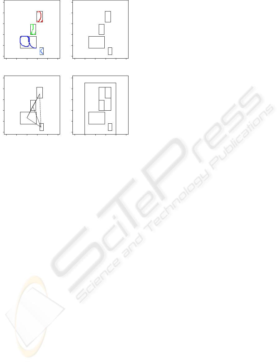
Figure 3 illustrates a complete process to build a
symbol expression graph including the segmentation
process and a topological and expression graph.
VISAPP 2009 - International Conference on Computer Vision Theory and Applications
252
0 20 40 60 80 100
0 20 40 60 80 100
x
y
cl1 (0)
cl2 (1)
cl3 (2)
cl4 (3)
0 20 40 60 80 100
0 20 40 60 80 100
x
y
2 (4)
2 (5)
a (6)
k (7)
0 20 40 60 80 100
0 20 40 60 80 100
x
y
2 (4)
2 (5)
a (6)
k (7)
NW
NW
N
SE
NW
N
SE
SE
NE
S
S
SW
0 20 40 60 80 100
0 20 40 60 80 100
x
y
super/subscript (28)
a (6)
k (7)
superscript (33)
2 (5)
2 (4)
Figure 3: Complete process to build symbol expression
graph - segmentation, topological and expression graph.
6 DEALING WITH OBJECT
INTERCEPTIONS
Dealing with object interception, we allow object rec-
ognizers to “consume” only part of the set of pixels
in a cluster. Remaining pixel cluster are reinserted in
the list of objects, as object of type cluster(.), to be,
possibly, further processed by additional object recog-
nizers. For example, a cluster representing the inter-
ception of a circle and line, may be first recognized as
a straight line, and the remaining pixel afterwards rec-
ognized as a circle. The robustness of the used mech-
anism to different types of interceptions and objects
is still subject for further investigations.
7 GROUPING OBJECTS
Since vector graphics and typessting systems often al-
low objects to be grouped (e.g. with combined trans-
formation, such as translation and scaling), the pro-
posed system also allow object grouping. This is done
interactively by combined selection via GUI, or us-
ing a close-by heuristic. Namely, objects with pixels
at a distance lower than a threshold θ
g
are grouped
together. Naturally, this may generate groups that
have objects further apart due to inclusion by asso-
ciativity (e.g., if we have a is −close b and b is −
close c, then by associativity a, b, c are included in
the same group. Relative positioning of individual
object is maintained in the object group. A group is
instantiated in the list of objects as an object of type
group(ob j
1
, . . . , ob j
n
), that can later be exported to
some file format.
8 EXPORTING TO VECTOR
GRAPHICS FORMATS
The presented system implementation allowed to ex-
port the list of recognized objects (geometry and sym-
bols) to several vector graphics languages and type-
setting systems. This is done simply by iterating over
the list of objects, and creating an equivalent object
in the target system or language for every found ob-
ject. In cases, where there is no direct conversion the
output may approximate the objects in some form.
SVG is a W3 standard for vector graphic repre-
sentations based on a XML syntax and technology.
Basic geometric objects, such as lines, polylines, and
circles, can be converted directly to SVG. Recog-
nized text symbols are mapped to SVG text objects.
We are investigating a way to approach the presenta-
tion in SVG of mathematical symbols not covered by
ASCII code and also Greek letters. We are working
to extend the system to export recognized geometries
and symbolic expressions to other vector languages
and/or type-setting systems. In particular, we plan to
export math formulas to TEX/L
A
T
E
Xand geometries to
one or several of its packages (such as fig, pstricks,
and xypic). SWF/Flash and direct PDF conversion
are also planned.
9 IMPLEMENTATION AND
INTERACTION
We have implemented a prototype version of the sys-
tem in the R statistics language and RTE for a fast
prototype and to test the robustness of the algorithms.
R RTE is slow, and it is hard to work as practical
system for complex images. GUI interaction mech-
anisms are also limited in R. We are currently work-
ing in a JAVA version, for higher performance, web
access, and elaborated interaction.
Since it is hard to define a common set of parame-
ters or order of application of recognizers to all im-
ages, GUI interaction is useful to define parameter
setting on a per-image basis. Moreover, in complex
images the best setting may depend on regions of the
image. To support this kind of detailed interaction, a
GUI has been developed to allow the user to set pa-
rameters and enable recognizers for specific regions.
BREADER: A MODULAR FRAMEWORK FOR VISION RECOGNITION OF MATHEMATICAL-LOGICAL
STRUCTURES
253

For example, if the user knows that a region of an
image only contains geometric elements, symbol and
expression recognition may be turn off.
10 RELATED WORK
The accurate recognition of Latin-script, typewritten
text is now considered largely a solved problem. Al-
though certain applications whith higher accuracy re-
quire human review for errors. Handwriting recogni-
tion problem, including recognition of hand printing,
cursive handwriting, is still the subject of active re-
search.
Systems for handwriting recognition are referred to
as off-line or on-line systems(Rjean Plamond, 2000).
Breader focus on off-line handwriting recognition,
since it does not assume a temporal dimension asso-
ciated to the writing action and recognition proccess.
Handwriting character and word recognition is an ap-
proach to symbol recognition and expression recog-
nition. Lee (Lee et al., 2007) describes a trainable,
multi-stroke symbol recognizer that is insensitive to
orientation, non-uniform scaling, and drawing order.
Progress has been reported in the area of dia-
gram recognition, although most projects have been
specific to a particular domain where recognition is
tailored to the symbols and graphical elements of
a particular type of diagram (Freeman and Plim-
mer, 2007; Chung et al., 2005). In (Kara and Sta-
hovich, 2004) the author present an approach for com-
bined recognition of hand-drawn and diagrammatic
sketches. Graph-based methods have been an been
used for object representation and matching, and have
been applied to hand-drawn pattern recognition prob-
lems (Chan and Yeung, 2000). With these methods,
sketched symbols are first decomposed into basic ge-
ometric primitives, such as lines and arcs, which are
then assembled into a graph structure that encodes
both the intrinsic attributes of the primitives and the
geometric relationships between them.
Different approaches have been proposed for sym-
bol recognition, including template matching ap-
proaches and structural approaches. Neuronal net-
work and statistical approaches (C.C. Tappert and
Wakahara, 1990; Mori et al., 1992) and algorithms
based on nearest-neighbor are most used methods for
implementing classifiers (Ha et al., 1995; Miller and
Viola, 1998).
Mathematical expressions recognition is a specific
form of pattern recognition that usually involves two
main stages: symbol recognition and structural anal-
ysis. Symbol recognition involve a sub-step to per-
form image segmentation followed by recognition of
individual text or mathemathical symbols. Structural
analysis is used to reconstruct the hierarchical struc-
ture of mathemathical expression. The survey paper
(Chan and Yeung, 2000), the authors review most of
the existing work on the topic.
Several papers explore specific problems related
to mathematical notation (Blostein and Grbavec,
1996). In (Miller and Viola, 1998), the author deal
with the particular issue of ambiguities that occur in
mathematical expression recognition. Ming et al.(Li,
2006), presents work to recognize printed mathemat-
ical expressions from document images, based on
method of parsing mathematics notation, which is
based on the combined strategy of baseline and mini-
mum spanning tree method.
A distinguishing feature of the architecure pro-
posed in this article is the focus on modularity, gen-
erality, extensability. Using a blackboard architec-
ture where symbolic representation of recognized ob-
jects can be posted and fetched allows incorporation
of new types of object recognizers. In particular, this
allows geometrical and symbolical structures as found
in mathemathical-logical expression to be recognized
in combination. This is particular useful in complex
diagrams such annotated graphs, many kinds of flow
diagrams, and most diagrams used in mathemathics,
science and engineering lectures.
11 CONCLUSIONS AND FUTURE
WORK
We presented a modular system architecture for com-
bined visual recognition of geometrical, symbolical,
mathematical structures. The system allow new kinds
of object recognizers to be added and selected as
needed. A “blackboard” data-structure is used to re-
tain all recognized object so far, and particular recog-
nizers check this list to discover new objects. Initially,
objects are simple pixel clusters resulting from image-
processing and segmentation operations. First-level
object recognizers include symbol/character recog-
nizers and basic geometric elements. Higher-level ob-
ject recognizers collect lower-level objects and build
more complex objects. This includes mathematical-
logical expressions, and complex geometric elements
such as polylines, graphs, and other. The recognized
objects and structures can be exported to a variety
of vector graphic languages and type-setting systems,
such as SVG and L
A
T
E
X. The systems also allow in-
teraction with the user, including selection of differ-
ent domains and/or recognizers in different regions of
the same image. Future work includes implementa-
tion of additional recognizers, including very high-
VISAPP 2009 - International Conference on Computer Vision Theory and Applications
254

level object such as graph, function plots, and generic
diagrams. Support for recognizers of more complex
mathematical expression such as found in matrix al-
gebra is desired. Mechanisms for coordination of
multiple types of recognizers, possibly independently
developed, is also subject to further investigation.
REFERENCES
Blostein, D. and Grbavec, A. (1996). Recognition of math-
ematical notation.
C.C. Tappert, C. S. and Wakahara, T. (1990). The state
of the art in on-line handwriting recognition. IEEE
Transactions on Pattern Analysis and Machine Intel-
ligence, 12:787–808.
Chan, K.-F. and Yeung, D.-Y. (2000). Mathematical expres-
sion recognition: a survey. IJDAR, 3(1):3–15.
Chung, R., Mirica, P., and Plimmer, B. (2005). Inkkit: a
generic design tool for the tablet pc. In CHINZ ’05:
Proceedings of the 6th ACM SIGCHI New Zealand
chapter’s international conference on Computer-
human interaction, pages 29–30. ACM.
Freeman, I. J. and Plimmer, B. (2007). Connector semantics
for sketched diagram recognition. In AUIC ’07: Pro-
ceedings of the eight Australasian conference on User
interface, pages 71–78. Australian Computer Society,
Inc.
Ha, J., Haralick, R., and Phillips, I. (1995). Understand-
ing mathematical expressions from document images.
icdar, 02:956.
Kara, L. B. and Stahovich, T. F. (2004). Hierarchical pars-
ing and recognition of hand-sketched diagrams. In
UIST ’04: Proceedings of the 17th annual ACM sym-
posium on User interface software and technology,
pages 13–22, New York, NY, USA. ACM.
Lee, W., Kara, L. B., and Stahovich, T. F. (2007). An ef-
ficient graph-based recognizer for hand-drawn sym-
bols. Comput. Graph., 31(4):554–567.
Li, M.-H. H. X.-D. T. N. (2006). Structural analysis of
printed mathematical expressions based on combined
strategy. Machine Learning and Cybernetics, 2006 In-
ternational Conference, pages 3354 – 3358.
Miller, E. G. and Viola, P. A. (1998). Ambiguity and con-
straint in mathematical expression recognition. Nat.
Conf. on Artif. Intell., pages 784–792.
Mori, S., Suen, C., , and Yamamoto, K. (1992). Historical
review of ocr research and development. Proceedings
of the IEEE, 80:1029–1058.
Nii, P. (1986). Blackboard systems part two: Blackboard
application systems. AI Mag., 7(3):82–106.
Rjean Plamond, S. N. S. (2000). On-line and off-line hand-
writing recognition: A comprehensive survey. IEEE
Transactions on Pattern Analysis and Machine Intel-
ligence, 22(1):63–84.
Smith, J. (1998). The Book. The publishing company, Lon-
don, 2nd edition.
BREADER: A MODULAR FRAMEWORK FOR VISION RECOGNITION OF MATHEMATICAL-LOGICAL
STRUCTURES
255
