
END-USER DEVELOPMENT IN A GRAPHICAL USER INTERFACE
SETTING
Martin Auer, Johannes P
¨
olz and Stefan Biffl
Institute of Software Technology and Interactive Systems, Vienna University of Technology
Favoritenstr. 9-11, A-1040 Vienna, Austria
Keywords:
End-user development, Software customization, UML, UML tools.
Abstract:
In many areas, software applications must be highly configurable - using a pre-defined set of options or pref-
erences is not flexible enough. One way to improve an application’s flexibility is to allow users to change
parts of the source code - and thus the application’s behavior - on-the-fly; modern languages like Java greatly
facilitate this by providing reflection features. Such an approach, however, is often limited to user-defined
mathematical formulas, e.g., in software like cash flow engines, reporting tools etc. This paper applies the
concept to a more generic area: the graphical representation of diagrams in a UML tool. Users can create new
types of graphical elements by directly programming how the elements are drawn, all within the UML tool,
and at run time. The approach is flexible, and the user-defined extensions are consistent with the tool’s core
source code.
1 INTRODUCTION
“Using a computer” evolved considerably over the
last decades from an end-user point of view. In the
early days, end users had to actually program the
computer, which provided only a basic set of func-
tionality. Soon, of course, some of those early pro-
grams evolved into ever more sophisticated special-
purpose applications to be distributed to an ever-
growing set of potential end users. These applica-
tions provided a specific, constrained set of high-
level functionality (e.g., the Unix set of command line
tools), while relieving end users from dealing with
low-level programming. This process towards spe-
cialized, stand-alone applications was consolidated
with the advent of graphical user interfaces (GUIs).
These apps provide higher-level functionality (e.g., a
word processor), and they are arguably easier to use
for a wider audience. However, the flexibility and
intra-tool communication is further restricted: the end
user can no longer tweak the tool thoroughly.
This outline - from basic, general-purpose pro-
gramming systems to less flexible, high-level custom
applications - greatly simplifies the manifold currents
in the evolution of software, its application and user
base, and its flexibility. Several counter-trends can be
readily identified:
1. Many modern applications (Eclipse, Excel,
Firefox, to name but a few) can be enhanced and
modified using plugins. The underlying tech-
niques differ; the approaches are similar: in an
external tool some partial functionality is defined
and packaged, and then attached to the main ap-
plication.
2. A variety of tools allows to add user-defined func-
tions or statements. OLAP applications, for ex-
ample, let users enter SQL statements if the usual
drag-and-drop GUI can’t easily assemble particu-
larly complex queries. Financial applications like
cash-flow engines and pricing tools let users enter
additional business logic and payoff functions—
basically additional mathematical formulas and
functions. Usually, the end user is allowed to ac-
cess some basic set of mathematical functions, to
which some restricted data structures are exposed.
The modifications can usually be done within the
tool, at run time.
3. On a larger scale, applications or operating sys-
tems can provide a whole macro language or
5
Auer M., Pölz J. and Biffl S. (2009).
END-USER DEVELOPMENT IN A GRAPHICAL USER INTERFACE SETTING.
In Proceedings of the 11th International Conference on Enterprise Information Systems - Human-Computer Interaction, pages 5-14
DOI: 10.5220/0001809800050014
Copyright
c
SciTePress

framework (VBA for MS Office, AppleScript..).
In this discussion, we’ll focus on VBA-like macro
languages due to their wide-spread use. This ap-
proach exposes more of the main application’s
functions and data structures to the end user. The
macro language’s scope, however, is often still
restricted to a subset of the internal APIs, in
part because the language is usually simpler that
the application’s core language (e.g., Basic vs.
C++). Often, inconsistencies arise: see, for exam-
ple, how Excel’s native cell formulas like MMult
are accessed within VBA. Advanced operations
are possible, but often require embedding exter-
nally created library functions (in VBA, with the
Declare Function command).
4. Finally, open source software discloses an appli-
cation’s entire source code. End users can inspect
and modify all aspects of the software. Users, par-
ticularly large institutions, regularly adapt open
source software to their needs, e.g., database soft-
ware like PostgreSQL is modified to handle new
data types.
Approach (1) is appealing—our main critique is the
media break: the plugin is developed externally and
must be included explicitly in the main application.
In many instances, it is preferable to allow run-time
modifications seamlessly, within the application, like
in approach (2).
Approach (4) is geared towards power users; other
end users might be overwhelmed by the setup and
sheer complexity of the code. Too much is exposed—
many parts of the code are unlikely to be modified.
The highest degree of flexibility is achieved, but at
the expense of severely reducing the target audience.
This paper describes an approach of providing
seamless flexibility for many end users, by letting
users alter parts of the core source code at run time.
Conceptually, it lies between approach (2) and ap-
proach (3):
• Users can access the full core API and data struc-
tures of the tool, unlike in (2). Not only mathe-
matical functions, but the graphical behavior and
the GUI’s reaction to user input can be modified.
• Users can use the tool’s core language (Java in our
case), not a stripped-down or simplified macro di-
alect. API calls and data access are thus consistent
in the user-defined code parts and the surrounding
original code, unlike in (3). This avoids redun-
dancies in the interfaces, data structures, and their
documentation; it is also preferable, for example,
if the code should later be included in the official
distribution branch of the application.
• There is no media break, i.e., no need for external
tools or explicit imports like in (1), or for external
DLLs like in (3). Such media breaks are tedious,
time-consuming and a prime source for errors.
• While the end user has access to the full range of
the internal API and data structures, he can mod-
ify only those parts of the code that are expected
to require this additional level of flexibility. The
proposed approach thus resembles “sand box”, as
opposed to the “sand bucket” in (2) or the “sand
mine” in (3).
This paper addresses two target audiences: end users
and developers of flexible software applications. To
end users we present where and how UMLet provides
flexibility. To developers we outline the implemen-
tation setting and some technical details. We argue
that users should demand this increased level of flex-
ibility, not only in a setting where they are allowed
to define mathematical expressions, but in ones with
more complex tool behavior as well. Developers, in
turn, should embrace this way of deferring design de-
cisions to later stages, up to the end user. Often, they
themselves will find that developing new tool features
is best done at run time, within the tool.
Section 2 gives on overview on related work. Sec-
tion 3 describes this paper’s goal in greater detail.
Section 4 outlines implementation issues. Section 5
presents several examples of UMLet’s end-user de-
velopment process. Section 6 concludes and points
out future research directions.
2 RELATED WORK
2.1 End-User Development
The concept of end-user development (EUD) - de-
fined by Beringer as a “design problem to enable
subject matter experts to create or modify executable
software components” (Beringer, 2004) - has been in-
vestigated for several decades (Martin, 1984). How-
ever, as several authors notice, the advances are be-
hind expectations (Sutcliffe, 2005; Fischer et al.,
2004). Beringer, for example, notes that EUD appli-
cations “only realize a fraction of EUD’s potential and
still suffer from several flaws” (Beringer et al., 2008).
He lists only a handful of partially successful applica-
tions, like macros, spreadsheets, and email filters.
The need for EUD applications, however, be-
comes more evident as increasing numbers of do-
main experts need to customize their software tools
to ever higher degrees, preferably at “use time” (Ko
and Myers, 2005): they become “unwitting program-
mers” (Costabile et al., 2008) as they evolve from cus-
ICEIS 2009 - International Conference on Enterprise Information Systems
6

tomizing software to creating new software function-
alities. Fischer identifies an even bigger group of end
users, the “much larger population of intellectually
disenfranchised knowledge workers who are forced
into a consumer role” as opposed to the traditional
“population of elite scribes who can act as design-
ers” (Fischer and Scharff, 2000).
Several papers describe the requirements for suc-
cessful EUD applications: Ruyter, for example,
stresses that such applications should be simple, give
proper user feedback, and motivate the end user to
play with the system (Ruyter and Sluis, 2006). Segal,
on the other hand, focuses on the problems such ap-
proaches need to deal with and overcome, especially
the problems of sharing knowledge and of software
reuse in a EUD context (Segal, 2007). Also, com-
mon important software engineering activities (like
documentation) are unlikely to be performed by the
task-focused end users (Segal, 2007). The “con-
flict between complexity and power” (Fischer et al.,
2004) leads Sutcliffe to a cost-benefit analysis of
EUD (Sutcliffe, 2005). Others, like Heng (Heng,
2003), emphazize the need for more communication
between system developers and end users to achieve
flexible and maintainable systems.
Another issue - the possible technical frameworks
underlying EUD applications - is discussed, for ex-
ample, by Paterno, who states the need for a transfor-
mation between intuitive representations of function-
ality to more precise, but more difficult to develop,
ones (Berti et al., 2006). Similarly, Fischer describes
some frameworks (like the high-level language Java)
as having a high cost of learning, and thus not being
an ideal EUD environment (Fischer et al., 2004).
Several organizations have recently focused on
this topic, for example, EUD-Net
1
, EUDISMES
2
,
EUSES
3
.
2.2 UML
The Unified Modeling Language (UML) (Booch
et al., 2005) is widely used for modeling object-
oriented software systems. It aims to cover most
parts of the software development process and has
been applied in various environments (e.g., real-time
systems (Evans and Wellings, 1999), or decentral-
ized production control systems (Kohler et al., 2000)).
It was developed between 1994 and 1997 by the “3
Amigos”: Jim Rumbaugh, Ivar Jacobson, and Grady
Booch. Version 1.1 was standardized in November
1
http://giove.isti.cnr.it/eud-net.htm
2
http://www.eudismes.de
3
http://eusesconsortium.org
1997 by the Object Management Group (OMG)
4
. The
OMG is a non-profit industry group now responsi-
ble for defining and maintaining the UML specifica-
tion. The next major revision—UML 2.0—became
the standard in October 2004 and since then evolved
to the current version 2.1.2 of the UML superstructure
and infrastructure specifications.
UML has unified and standardized the concepts
of previous graphical notations like Booch or OMT.
It currently features six types of structure diagrams
(e.g., class diagram, deployment diagram..), as well
as seven types of behavior diagrams (e.g., activity di-
agram, use case diagram..). All in all, UML defines
more than 130 elements
5
; new ones are being added
in each new version. This puts some strain on UML
tools—they often do not cover the whole range of the
graphical notation, and need to be continuously up-
dated to reflect new UML versions.
Due to the widespread use of UML, a large num-
ber of tools is available. According to Smith (Smith,
2004), these can be categorized into:
• UML drawing tools;
• code-centric tools; and
• framework tools.
UML drawing tools focus on fast diagram sketch-
ing and offer great flexibility. Code-centric tools re-
strict the UML specification to fit specific program-
ming languages, but provide additional features like
code generation and reverse engineering. Framework
tools go one step further by supplying the user with
extended code generation mechanisms as well as pro-
viding automated test case generation.
An overview of many UML tools is available on
Jeckle’s Web site
6
. IBM Rational Rose
7
and Vi-
sual Paradigm
8
are two commonly used commercial
framework tools that attempt to support a host of de-
velopment procedures, as well as code generation and
reverse engineering. In contrast, the open source tool
UMLet
9
(Auer et al., 2003) concentrates on fast di-
agram sketching (Auer et al., 2007) and flexibility.
Another aspect of UMLet—presented in this paper—
is the adaptability to new element types via custom
elements, where users can define new UML element
types at run time.
4
http://www.omg.org
5
http://www.omg.org/spec/UML/2.1.2
6
http://www.jeckle.de
7
http://www-306.ibm.com/software/awdtools/developer/rose
8
http://www.visual-paradigm.com
9
http://www.umlet.com
END-USER DEVELOPMENT IN A GRAPHICAL USER INTERFACE SETTING
7
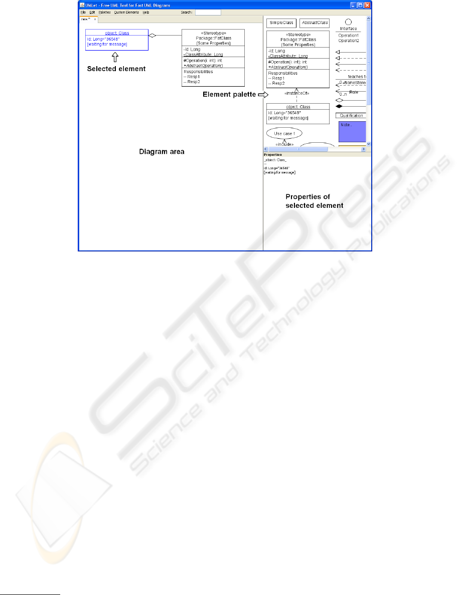
Figure 1: UMLet screenshot.
2.3 Reflection
Reflection is the ability of a programming language
to query and operate with language meta-information,
e.g., to get a list of all available members of a class
in an object-oriented framework. Cazzola (Cazzola
et al., 2000) describes its properties of “transparency,
separation of concerns, and extensibility” as “ac-
cepted as useful for software development and de-
sign” and as “likely to be of increasing relevance in
the modern software engineering scenario”.
Reflection is especially useful to delay parts of
a software design from compile time to run time.
This property is valueable for addressing flexibility
issues in modern software development—it is applied
in COTS components (e.g., Hibernate
10
), in plug-
and-play supporting software (e.g., Firefox
11
), and in
highly customizable software (e.g., UMLet).
A prominent example of a language providing re-
flection capabilities is Java. An established applica-
tion of reflection concepts in the Java environment
is, e.g., the Enterprise JavaBeans component technol-
ogy
12
.
10
http://www.hibernate.org
11
http://www.mozilla-europe.org/en/firefox
12
http://java.sun.com/products/ejb
3 GOALS AND APPROACH
UML defines a wide variety of graphical elements;
each new UML version modifies them, or adds new
ones—so there is a constant need for UML tool up-
dates. End users can thus either wait for a new ver-
sion of a given UML tool, or design their own UML
elements. This paper proposes a way how end users
can develop such new graphical elements within the
UML tool UMLet (Auer et al., 2003).
Following Ruyter’s suggestions (Ruyter and Sluis,
2006), the goal is to keep the approach simple and
to provide immediate feedback to the user—see sec-
tion 3.1. The way users create new elements is that
they can specify—via Java code—how new elements
are painted. This definition takes place within the tool
UMLet, at run time. To reduce the complexity of this
user generated code we use a code frame or template
to avoid exposing unnecessarily complex objects to
the user—see section 3.3.
We use Java as end-user programming language.
The main reason for choosing Java is the greater flexi-
bility compared to a custom domain specific language
(DSL). This allows the user to access both some meth-
ods pre-defined for user convenience, as well as Java’s
complete set of graphics and core libraries. Further-
more, Java’s reflection features make the implemen-
tation of this additional degree of flexibility straight-
forward. Another reason for using a popular object-
ICEIS 2009 - International Conference on Enterprise Information Systems
8
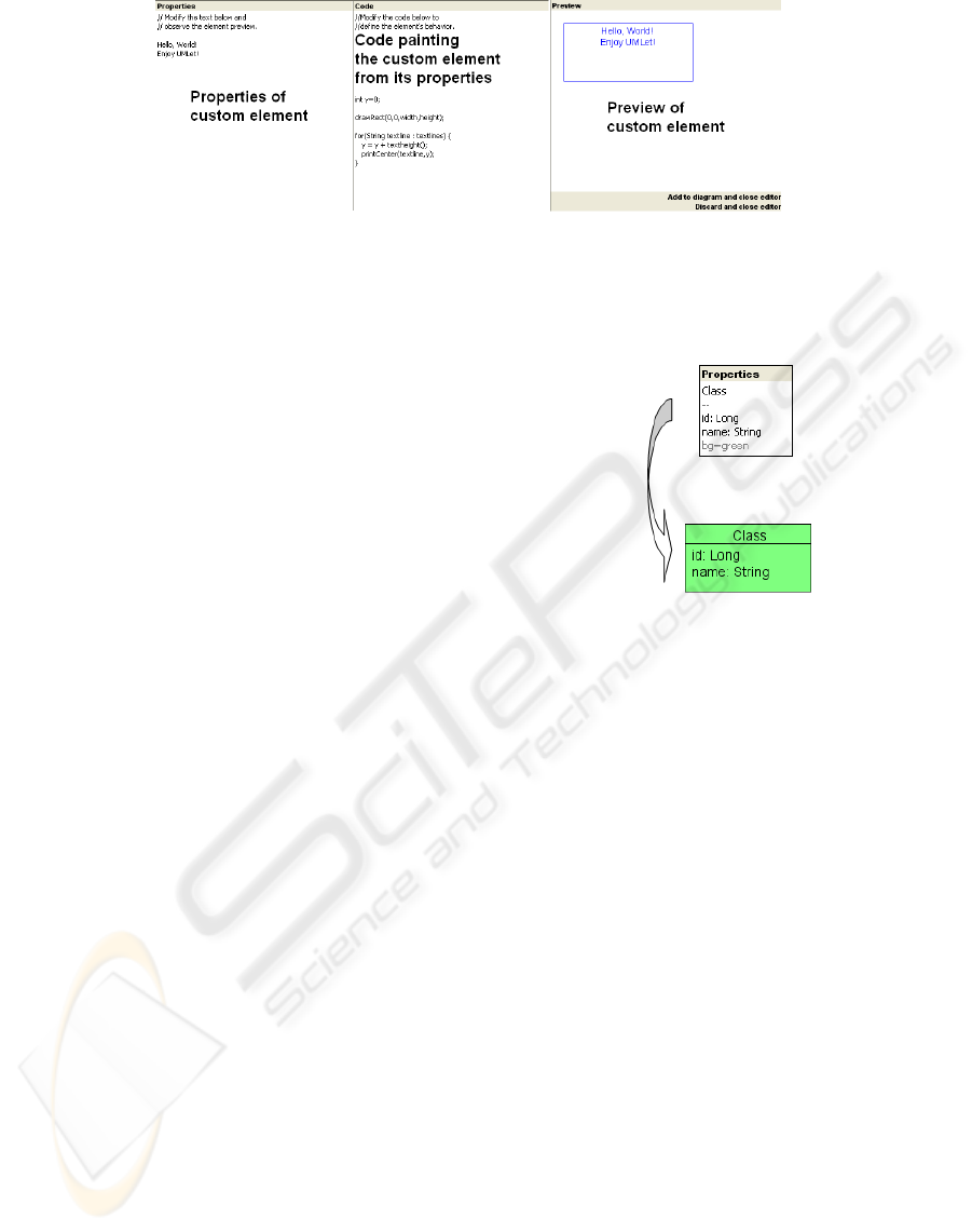
Figure 2: UMLet screenshot. - custom element UI
oriented language is that many UML tool users are
already familiar with it.
3.1 UMLet’s User Interface
UMLet’s user interface (figure 1) basically provides
three panels - the diagram panel, the palette panel,
and the property panel. The diagram panel, of course,
displays the diagram and all the UML elements it con-
tains, and lets the user modify their location—just
like other graphical tools. The palette panel exposes
all available elements and lets users add instances of
those elements to the diagram panel (it does not rep-
resent elements by icons; instead, it represents them
like they would look on the diagram). Finally, the
properties panel is a text panel that lets users view
and modify the properties of a UML element.
In most UML tools, element properties are modi-
fied via pop-up windows, where users can change el-
ement attributes. The property panel in UMLet pro-
vides a shortcut to this workflow: it displays—as a
single string—all relevant properties; users can fast
and easily modify the element’s properties by chang-
ing this string. For example, to add new methods to a
UML class element, one can simply enter their names
as several new lines to the string given in the property
panel.
For each UML element, UMLet’s display or draw-
ing logic is simple: the string given in the property
panel is interpreted, and the graphical representation
of that UML element is modified according to this in-
terpretation. More specifically, all UML elements on
a diagram correspond to a Java object that “draws it-
self”, i.e., interprets its own property panel string and
modifies its own graphical representation.
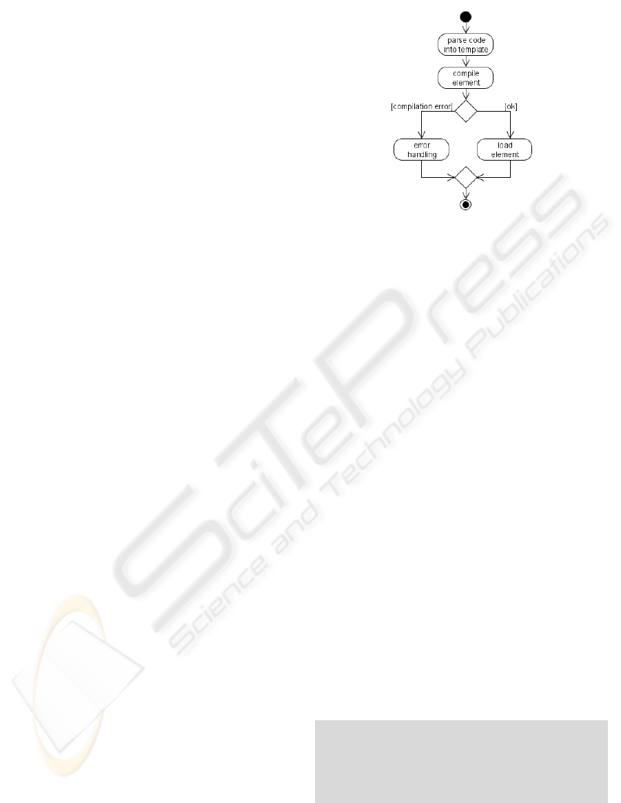
For example, in figure 3 the property panel’s text
of a UML class element is interpreted by that class
element to draw itself. The first line is interpreted as
the class name and printed on top of the class, aligned
centrally. Subsequent lines are treated as method or
attribute names, which are printed left-aligned. The
string “– –” (a double dash) is interpreted as a hor-
izontal line separating class name, attribute names,
and method names; the string “bg=green” sets the el-
ement’s background color to green.
Figure 3: Property text parsing example.
3.2 Custom Elements
To keep the development of new custom elements
simple, the development environment has to be in-
tegrated into the application itself. Integration via a
separate window or by providing a plugin interface
would be possible, but it would represent a media
break and an additional barrier for end users. A more
direct way is provided: as soon as a new custom ele-
ment is created, the property panel expands into three
panels. The panels shown in figure 2 are (from left
to right) the property panel, a source code panel, and
a preview panel. The user can now modify the cus-
tom elements on two different levels. First, as be-
fore, he can change the text in the property panel and
see the consequences in the graphical representation
in the preview panel. But in addition, in the source
code panel he can change the source code that is re-
sponsible for interpreting the property panel text and
for drawing the element in the preview panel. At the
same time, thus, a user can change an element’s prop-
erties, and how those properties are transformed into
a graphical representation.
The code is compiled continuously in the back-
ground, and immediate feedback is provided to the
end user by re-drawing the element in the preview
panel. If the code contains errors, the affected source
END-USER DEVELOPMENT IN A GRAPHICAL USER INTERFACE SETTING
9
code lines are highlighted. Several examples of sim-
ple custom elements are shown in section 5.
3.3 Code Template
End users can thus modify the Java code that de-
termines how a UML element properties are con-
verted to that UML element’s graphical representa-
tion. To avoid exposing to much application logic to
the end user, UMLet provides a code template that
hides most of the the UML element’s internal struc-
ture (i.e., its Java class definition) from the user. Now,
the user only has to modify the source code for a
single method—the drawing method of the graphi-
cal component. Implementing a single method rather
than a full class is easier because it does not re-
quire background knowledge of the object-oriented
architecture; in addition, most surrounding or sup-
port functionality—like file dialogs, context menus,
file exports—are unlikely to need change, and would
only be a distraction.
Another simplification is that the user does not
need to worry about color settings and command pars-
ing. In general, this is done by a global parsing
method. The template takes care of applying the
global parsing mechanism like the color settings, or
the default behavior of element resizing. This way,
some settings are consistent for all, even newly cre-
ated, elements. Only properties specific to a new ele-
ment have to be processed by the user’s code.
Whenever the user’s code needs to be compiled, it
is inserted at the appropriate position in the template
class, and the entire class is compiled. If successful,
the element is generated (i.e., an object of that class is
instantiated), and put on the preview panel, where it
draws itself using the user-provided drawing method.
4 IMPLEMENTATION
The following sections gives a brief implementation
overview of the approach presented in section 3: it de-
scribes the workflow to create a new custom element,
the available predefined methods, the saving of cus-
tom elements, error handling, and code completion.
Finally, some security issues are discussed that arise
when custom elements are exchanged between users.
Although UMLet is implemented in Java, the imple-
mentation details are presented—when possible—in
a language-independent way. The approach should
be readily applicable in other programming languages
that support reflection, provide a compilation API,
and some sort of security manager.
Figure 4: Compilation process.
4.1 Element Generation
The general workflow of the element generation is
shown in figures 4.
First, the custom element class is generated by in-
serting the user code into the template. Then the class
is compiled, loaded, and instantiated via the Java class
loading mechanism. If a compilation error occurs, an
error element is returned instead. After a successful
compilation the generated element may be used just
like predefined elements.
4.2 Class Template Api
The template class provides several predefined meth-
ods. Since the entire Java API is still available, these
methods are not a restriction for the end user but
rather a help to get started.
4.2.1 Text Drawing Methods
The text drawing methods provide the user with draw-
ing functionality such as text printing and boundary
calculation. Text can be printed at either a fixed po-
sition or at a fixed vertical position with an alignment
relative to the element’s horizontal bounds.
The textheight and textwidth methods return a text
line’s height and width in pixels.
void print ( String text , i nt x , in t y)
vo i d prin t L e f t ( St r i ng te xt , in t y)
vo i d pri n t R i g h t ( St r i n g text , in t y )
vo i d pr i n t C e n t e r ( St r i n g tex t , int y )
in t t ex t h e i g h t ( )
in t t ex t w i d t h ( St r i n g t e x t )
ICEIS 2009 - International Conference on Enterprise Information Systems
10

Figure 5: Compilation panel.
4.2.2 Drawing Methods
The predefined drawing methods just call some of the
Java AWT package’s drawing methods. The advan-
tage when using these methods is that they automati-
cally use a consistent back- and foreground color han-
dling.
vo i d drawRec t ( i nt x , in t y , in t w id th , int heig h t )
vo i d drawLin e ( i nt x 1, in t y 1 , in t x 2 , in t y 2 )
vo i d d r a w L in e H o ri z o nt a l ( int y )
vo i d d r a w L i ne V e r ti c a l ( int x )
vo i d dra w C i r c l e ( int x , in t y , int radius )
vo i d dr a w E l l i p s e ( int x , in t y , int r a d ius X , in t
radiusY )
vo i d dr a w P o l y g o n ( Polygon p o l y g o n )
4.2.3 Resizing Methods
Resizing methods help the user to handle ele-
ments that dynamically resize themselves. If the
allowResize method is invoked with the value false,
the user will be unable to resize the element manu-
ally. In this case the element’s dimensions have to be
set in the—user-provided—paint method.
The setElementCentered method moves the ele-
ment’s anchor point to its horizontal center. Any up-
date to the element’s width is then applied in equal
measure on both sides. If the element resizable—i.e.,
the allowResize(false) method has not been called—
the setElementCentered method has no effect.
The isManualResized() method enables the han-
dling both manual and automatic resizing. The el-
ement’s dimensions still have to be computed in its
paint method but only if isManualResized() returns
false. It returns true if the user has already manually
resized the element—in this case, automatic resizing
is suppressed. To switch back to automatic resizing,
the user has to remove the property autoresize=false
that is automatically added to the element’s properties
as soon as the user manually resizes the element.
vo i d al l o w R e s i z e ( boolean a l l o w )
vo i d s e t E l em e n t Ce n t er e d ( )
boolean i sM a n u al R e s iz e d ( )
4.2.4 Other Methods
The addStickingPoint method alters the element’s
sticking polygon. The sticking polygon specifies
where exactly UML relations (basically, the arrows
in a diagram) stick to the element and if they should
be repositioned when a UML element they stick to is
moved by the user. The sticking polygon defaults to a
rectangle enclosing the entire element.
The min and max methods return the minimum
or maximum of its parameters. This is a shortcut to
Java’s Math package to provide faster access to these
frequently used methods.
in t m in ( in t v a l u e 1, i nt v alue 2)
in t m ax ( in t v a l u e 1, i nt v alue 2)
vo i d a d d S t i ck i n g Po i n t ( int x , in t y )
4.3 Error Handling
The error handling mechanism (figure 5) for show-
ing compilation errors in the code follows standard
IDE conventions: it takes the generated compiler er-
ror messages and marks the erroneous lines. If the
user moves the mouse over those lines, the error mes-
sage is displayed.
4.4 Code Completion
Many popular development tools (e.g., Eclipse) im-
plement a code completion feature, where a list of
all available methods and variables is displayed as the
user types. In order to provide the user with a quick
overview of the available predefined methods (see
section 4.2), the method prefixes are displayed when
the user moves to an empty line (figure 5); as soon as
the user starts typing, a detailed list of methods and
variables matching the user input is displayed.
4.5 Saving and Sharing an Element
There are several ways to save and distribute a custom
element; they have different advantages and disadvan-
tages:
END-USER DEVELOPMENT IN A GRAPHICAL USER INTERFACE SETTING
11
1. The custom elements can be stored in separate
files, or within the UML diagram file they are part
of.
2. The custom elements can be stored as Java code,
or as compiled class file.
3. If a copy of a custom element is created on the
same or a different diagram, it can be treated as
another instance of the same custom element (the
copy changes when the original custom element’s
source code is modified), or as a new type of cus-
tom element (changes to the source code in the
original custom element do not affect the copy).
UMLet stores the element’s code directly in the dia-
gram (or palette) containing the element, mostly be-
cause it eases the exchange of diagrams as they re-
main single, self-contained files, and don’t exhibit ad-
ditional dependencies on external files. To keep the
diagram file as small as possible, only the user’s code
is stored, not the surrounding template class. Loading
a custom element internally works just like generating
a new custom element—see section 4.1. The obvious
drawback is the performance impact when loading a
diagram that contains a large number of custom el-
ements. The transparency of the source code-based
file format, though, makes up for the performance
penalty.
Finally, UMLet treats copies of custom elements
as new element types, instead of new instances of the
same element type, in order to handle copies of ele-
ments within a diagram and between diagrams con-
sistently.
One drawback of this “hidden” element exchange
is that an attacker could distribute diagrams contain-
ing malicious custom elements. This security aspect
will be discussed in more detail in section 4.6.
4.6 Security
As mentioned in section 4.5, loading a custom ele-
ment may be a security risk if the user is allowed to
use the entire scope of the underlying programming
language (e.g., a custom element could access the file
system). To protect end-user systems from damage,
several measures can be taken.
The first measure is very easy to implement and
thus commonly used. Whenever a diagram contain-
ing custom elements is loaded, a warning message
that informs the user about the potential risk is dis-
played. The diagram is only loaded after the user con-
firms that the source can be trusted. One problem with
this simple solution is that a lot of users will ignore
these warnings as they are not aware of security risks
or have become insensitive to security related alerts.
Even if the user is aware of the risks he may be still
be fooled to open a malicious diagram—e.g., if the
attacker resembles a trusted source. Another problem
is that users may create malicious elements by acci-
dent and thus harm their own system during custom
element development.
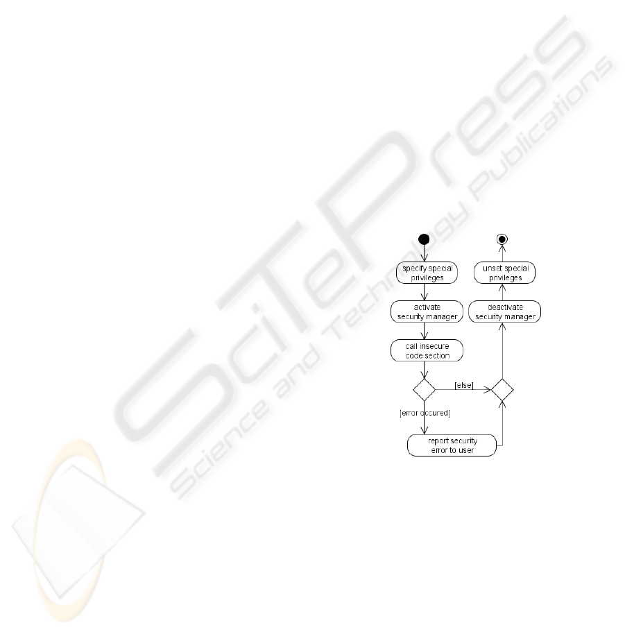
The second security measure does not depend on
the user but relies on the programming language’s se-
curity mechanism. First, all but the paint method of
the abstract custom element class are declared as final
methods—this ensures that these methods cannot be
overridden by the custom element. As a consequence,
custom code can only be placed in the paint method,
even if the attacker finds a way to break out of it. A
security manager (like the one in Java) then enforces
that no security critical operations (e.g., file access)
are performed during execution of the paint method.
To ensure that end users are unable to deactivate the
security manager, a random token only visible to the
method calling the paint method is used for authenti-
cation.
Figure 6 gives an overview how a method call to
paint is handled.
Figure 6: Security workflow.
5 EXAMPLES
The following four custom element examples give a
quick overview of UMLet’s live-compilation possibil-
ities. The examples’ figures show the property panel,
the code panel, and the preview panel.
The textlines variable inside the code panel con-
tains the property panel’s text. The user code then
parses this text to generate the appropriate graphical
representation for the preview panel.
As soon as the source code is modified in the
ICEIS 2009 - International Conference on Enterprise Information Systems
12
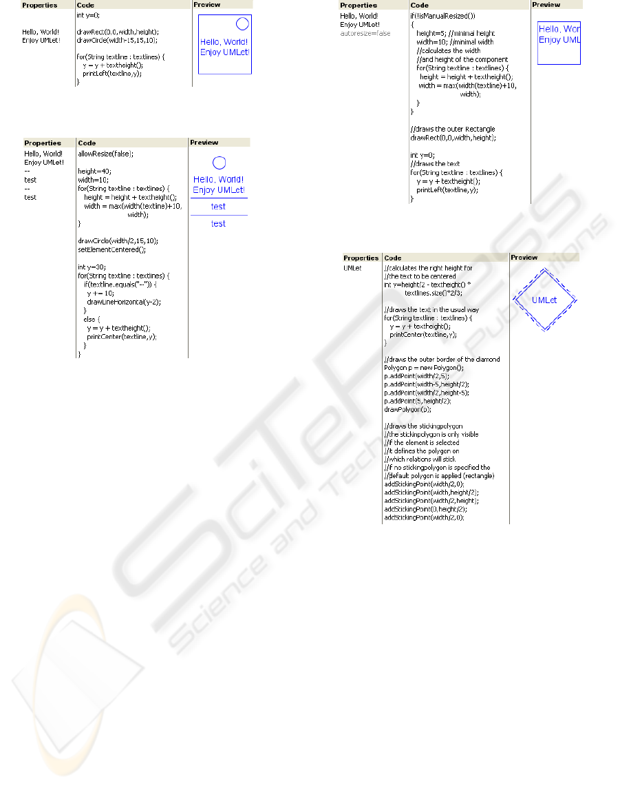
Figure 7: Custom element example 1.
Figure 8: Custom element example 2.
source code panel, the code is recompiled. If it com-
piles successfully, the code is applied to the text in
the property panel and the element’s preview is up-
dated. If the property panel’s text is changed, the last
successfully compiled code version is applied to the
changed property text, and the element’s preview is
refreshed.
The example shown in figure 7 creates a rectan-
gular textual element with a small circle in the upper
right corner. The drawCircle and drawRect method
calls draw the bounding rectangle and the circle in
the element’s upper right corner. Finally, the for-loop
draws the text that has been entered in the property
panel.
Figure 8 shows an example with more complex
functionality. It prevents the user from manually re-
sizing the element by calling the allowResize(false)
method and goes on to calculate the component’s di-
mensions. The setElementCentered method moves
the element’s anchor point to its horizontal center.
Any update to the element’s width is then applied in
equal measure on both sides. The for-loop not only
draws the text but also tests for lines containing “– –”
and draws a horizontal line instead.
The example in figure 9 adds optional manual re-
sizing to the element. The isManualResized function
automatically checks if the element has been resized
manually. As soon as the user resizes the element,
the autoresize=false string is appended to the prop-
Figure 9: Custom element example 3.
Figure 10: Custom element example 4.
erty panel. The function isManualResized returns
true whenever the property panel contains that string
(autoresize=false). In example 9, the user has already
resized the element manually so the if-block that cal-
culates the size automatically is not executed. As
soon as the autoresize=false string is removed from
the property panel, the size is computed and adjusted
automatically again.
The last example in figure 10 demonstrates the
implementation of sticking polygons, which specify
where relations stick to a UML element on the dia-
gram. The addStickingPoint method adds points to
the sticking polygon. At least two points are required.
The sticking polygon is drawn as dashed lines. If
no polygon is specified, the relations will stick to the
rectangle defined by the outer borders of the compo-
nent. The other methods used in example 10 are sim-
ple: first the text is drawn at the center of the element;
then a diamond is drawn around it.
END-USER DEVELOPMENT IN A GRAPHICAL USER INTERFACE SETTING
13

6 CONCLUSIONS
Letting users extend applications by programming
has been a research topic for quite some time without
producing many widely-used results (except custom
mathematical expressions). In this paper we describe
a UML tool that enables users to create new graphical
UML elements by using the internal graphical API of
the tool itself. While this is a very special application,
the concept may be applied to other areas.
The approach is simple and provides immedi-
ate feedback to the end, addressing Ruyter’s require-
ments for successful EUD applications. A crucial dif-
ferences to other end-user development approaches is
that the development environment is integrated into
the main application window and thus no media break
occurs. In addition, this paper addresses several prob-
lems including persisting the code, exchanging ele-
ments and security.
Future research will focus on an easier exchange
of custom elements between end users, potentially
over a Web service, and on custom UML relation
types.
REFERENCES
Auer, M., Meyer, L., and Biffl, S. (2007). Explorative UML
modeling: Comparing the usability of UML tools.
In Proceedings of the 9th International Conference
on Enterprise Information Systems (ICEIS’07), pages
466–474, Madeira.
Auer, M., Tschurtschenthaler, T., and Biffl, S. (2003). A fly-
weight UML modeling tool for software development
in heterogeneous environments. In Proceedings of the
29th EUROMICRO Conference, pages 267–272, An-
talya.
Beringer, J. (2004). Reducing expertise tension. Communi-
cations of the ACM, 47(9):39–40.
Beringer, J., Fischer, G., Mussio, P., Myers, B., Patern, F.,
and Ruyter, B. d. (2008). The next challenge: From
easy-to-use to easy-to-develop. Are you ready? In
Proceedings of the Conference on Human Factors in
Computing Systems (CHI’08), pages 2257–2260, Flo-
rence.
Berti, S., Patern, F., and Santoro, C. (2006). Natural de-
velopment of nomadic interfaces based on conceptual
descriptions. In End-User Development, pages 143–
160. Springer.
Booch, G., Rumbaugh, J., and Jacobson, I. (2005). The Uni-
fied Modeling Language User Guide. Addison Wes-
ley, 2. edition.
Cazzola, W., Stroud, R., and Tisato, F. (2000). Reflection
and Software Engineering. Springer.
Costabile, M., Mussio, P., Provenza, L., and Piccinno, A.
(2008). End users as unwitting software developers.
In Proceedings of the 4th International Workshop on
End-User Software Engineering (WEUSE’08), pages
6–10, Leipzig.
Evans, A. and Wellings, A. (1999). UML and the formal
development of safety-critical real-time systems. In
IEE Colloquium on Applicable Modelling, Verifica-
tion and Analysis Techniques for Real-Time Systems,
pages 2/1–2/4.
Fischer, G., Giaccardi, E., Ye, Y., Sutcliffe, A., and
Mehandjiev, N. (2004). Meta-design: A manifesto for
end-user development. Communications of the ACM,
47(9):33–37.
Fischer, G. and Scharff, E. (2000). Meta-design: Design for
designers. In Proceedings of the 3rd Conference on
Designing Interactive Systems (DIS’00), pages 396–
405, New York.
Heng, M. (2003). Beyond end user computing. In Pro-
ceedings of the 5th International Conference on En-
terprise Information Systems (ICEIS’03), pages 594–
598, Angers.
Ko, A. and Myers, B. (2005). A framework and methodol-
ogy for studying the causes of software errors in pro-
gramming systems. Journal of Visual Languages &
Computing, 16(1-2):41–84.
Kohler, H., Nickel, U., Niere, J., and Zndorf, A. (2000). In-
tegrating UML diagrams for production control sys-
tems. In Proceedings of the 22nd International Con-
ference on Software Engineering (ICSE’00), pages
241–251, Limerick.
Martin, J. (1984). An Information Systems Manifesto. Pren-
tice Hall, 1. edition.
Ruyter, B. d. and Sluis, R. v. d. (2006). Challenges for end-
user development in intelligent environments. In End-
User Development, pages 243–250. Springer.
Segal, J. (2007). Some problems of professional end-user
developers. In Proceedings of the IEEE Symposium
on Visual Languages and Human-Centric Computing
(VL/HCC’07), pages 111–118, Coeur d’Alne.
Smith, H. (2004). On tool selection for illustrating the use of
UML in system development. Journal of Computing
Sciences in Colleges, 19(5):53–63.
Sutcliffe, A. (2005). Evaluating the costs and benefits of
end-user development. SIGSOFT Software Engineer-
ing Notes, 30(4):1–4.
ICEIS 2009 - International Conference on Enterprise Information Systems
14
