
An Unconventional Approach to Healthcare
(Geographic) Information Systems using a Custom
VB Interface to AutoCAD
Ernesto Iadanza
Dept. of Electronics and Telecommunications Università degli Studi di Firenze
Via S. Marta 3, 50139 Firenze, Italy
Abstract. This article shows how to approach to complexity government in a
healthcare structure, using biomedical and architectural skills together with
informatics to improve healthcare management. The approach proposed in this
work is different from the standard GIS approach because it tends not to
separate graphical data and informative data.The developed system, called
SACS, is a custom VB software that drives Autocad. It provides a mapping of
every single hospital room in terms of beds, square meters, destination of use,
functional area and many other details. Each room is considered as a part of a
ward introducing the concept of Main Destination of Use (MDU). System
reports can be used via web by the hospital top management as well as by the
clinical engineer, who can assess parameters like the maintenance state of an
equipment or its obsolescence, being aware of the hospital context in which this
equipment has been used.
1 Introduction
The acronym GIS (Graphical Information System) is used for an IT system to
produce, manage and analyze spatial data, connecting each geographic element to
alphanumeric descriptions. It mainly manages and elaborates georeferenced data that
is saved in an external database. In the last few years GIS has entered the public
health management systems as well. [1] [2] [3]
The approach proposed in this work is different from the standard GIS approach
because it tends not to separate graphical data and informative data.
In most hospitals’ technical departments there are plenty of CAD mappings for the
whole building estate. These drawings are mainly used for maintenance purposes, but
(if up to date) they can become a great source of information for healthcare managers
as well. [5]
Besides architectonical and fittings data (area, number of medical gasses connections,
etc.) much more information can be found linked to the particular room (destination
of use, ward beds, etc.) as well as information about the staff that uses that particular
room (doctors, nurses, students). This data, if conveniently structured and linked to
the Hospital Information System (HIS), can become a powerful data source for the
technical management as well as to the top management. [7]
Iadanza E. (2009).
An Unconventional Approach to Healthcare (Geographic) Information Systems using a Custom VB Interface to AutoCAD.
In Proceedings of the 1st International Workshop on Mobilizing Health Information to Support Healthcare-related Knowledge Work, pages 13-19
DOI: 10.5220/0001812800130019
Copyright
c
SciTePress
By integrating other information (first of all healthcare technology equipment) this
cartography could become part and parcel of the HIS itself.
2 Methods
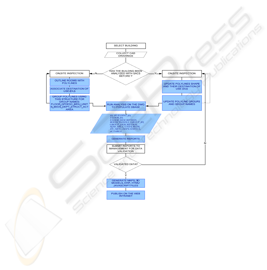
The proposed system, called SACS (an Italian acronym that means system for the
analysis of the hospital equipment) consists of both a methodology (fig. 1) and a
custom VB software that drives Autocad [4]. The DWG file is manipulated using
SACS – that acts as a filter-interface to the CAD – to input the information gathered
during the on-the-spot investigation. Then SACS is used to extract these data, link it
to other data from the HIS database, publish reports and make HTML and DWF files
that can be put on the hospital Intranet.
Fig. 1. Process flowchart. Blue steps are performed using SACS.
2.1 Data Input: Wards as Polylines Groups
The first hitch to overcome is the heterogeneousness of the cartography. This
information is supplied by the technical/logistical department, by the safety
department, or from external consultants in charge of inspection campaigns.
14

Without a prescribed standard, these CAD drawings are non standard under many
aspects like the criteria used to name layers, the physical positioning of additional
data, the updating level, etc. This matter is overcome by recasting each DWG file,
creating a new reserved layer to SACS software, in which the rooms are outlined by
closed polylines.
The purpose of this work was to insert the whole information directly inside the DWG
file, forcing its use as a database. The external HIS database can still be used, but just
as a “reading key” to translate the synthetic information held by the DWG file, using
some support tables to describe the various parameters. This approach makes it
possible to rebuild anytime the whole information having nothing but the DWG file.
Polyline colour is used as a parameter to identify the destination of use. Hence, the
software is provided with a module to make multiple selections on the DWG file and
to give to selected polylines a colour index (using the colour property of the
AcadPolyline object) chosen by a list (dbList) of 22 destinations of use (DU) coming
from a database accessed via ODBC.
One of the purposes of the proposed system is to compare the space reserved to the
various functions with that suggested by literature standards. To do that, it must be
introduced in the model the concept of “main destination of use” (MDU). This
parameter considers each room in the operative context in which it is inserted.
Therefore some rooms are linked together by a functional connection.
The software implements this approach by using Autocad groups feature. Polylines
are grouped by homogeneous functional areas; group name is then used as an array of
fields separated by underscores according to following syntax:
FLOOR_GPDESC_MDU_UNITS_BEDS_DEPT_STRUCT_ACTAREA
where
- FLOOR is the level inside the building, useful for multi-floor drawings
- GPDESC is a brief description of the polylines group
- MDU is the prevalent destination of use (each group is generally made by
polylines with different DU)
- UNITS is the actual number of rooms in the group with DU=PDU; this
number can be different from the mere automatic count of polylines and is
intended to be use as a “fine manual adjust”
- BEDS is the total number of ward beds in the group
- DEPT is the department code (useful when the actual amount of structures
that use the rooms is unknown)
- STRUCT is a combination of codes representing the operative structures that
use the rooms. When they belong to different departments, the DEPT field is
left blank.
- ACTAREA is a number code that represents the Activity Area. The whole
hospital is divided by activity areas that belong to a single department.
2.2 Data Update and Output
The most demanding phase in the whole process is the first one, as described above in
Section 2.1. Actually the proposed method shows its biggest power in the subsequent
15
steps, making really fast the updating step. This can be scheduled or made upon
request of the management while relocating some hospital functions.
Besides, the software can be usefully employed by the head office together with
technical department and clinical engineering department using a WHAT-IF method
to make spatial simulations and to perform architectonical or technological renewal
plans.
The information in each file, once processed as described, is extracted by the software
and inserted in a support table via ODBC in order to generate some reports including
key performance indicators [6]. Table fields are the following:
- ID
- BUILDING_ID, much useful in pavilions hospitals
- FLOOR_ID
- FLOOR_DESCRIPTION
- ROOM_HANDLE, given by CAD as the polyline handle
- GROUP_ID
- GROUP_DESCRIPTION
- SQM_AREA, room area in square meters
- UNITS (see above – Section 2.1)
- BEDS (see above – Section 2.1)
- DU, the room destination of use
- MDU, the main destination of use of the functional group to which the room
belongs
- DEPT (see above – Section 2.1)
- STRUCT (see above – Section 2.1)
- ACTAREA (see above – Section 2.1)
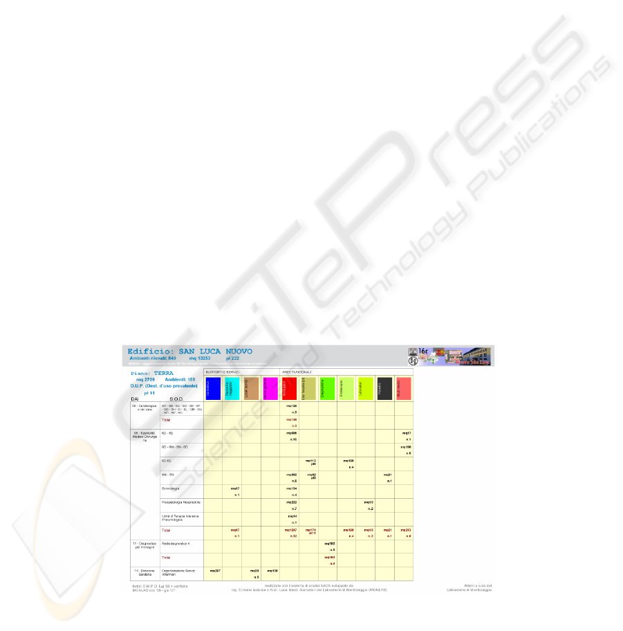
Starting from this table SACS allows to publish detailed reports arranged by building
(fig. 2) or by operative structure (useful to study the scattering of a functional unit in
the hospital estate and to plan possible improvements.
Fig. 2. Sample numerical report.
16
2.3 Intranet
To make the information accessible via web using the hospital Intranet, the software
takes advantage of AutoCAD’s hyperlink feature. It is possible to associate to every
single polyline an hypertextual link and then publish the drawings in a DWF format,
visible with a web browser and a free plug-in (available on Autodesk website).
SACS uses the hyperlink property as follows: in the hyperlink descriptions it inserts
an abstract of the information about the room and about the group to which it belongs
(DU, MDU, SQM_AREA, HANDLE, DEPT, STRUCT, etc.). In the hyperlink target it
puts a string like this:
GROUP_NAME & “#” & HANDLE
Then the software produces, for each polyline group, an HTML/JAVASCRIPT file
called
GROUP_NAME & “.HTML”
In this file, the data for the whole group and for the single polylines that compose the
group are summarized. The JAVASCRIPT code is used to highlight in red the data for
the particular polyline identified by the hex handle extracted from the URL starting
from the “#” character.
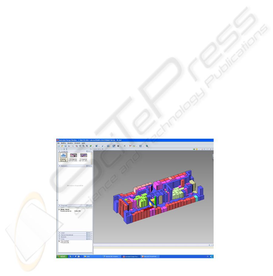
The belonging of the polylines to the different groups is emphasized by means of a
3D solid modelling. Each polyline is associated to extruded regions which are
coloured according to their destination of use. The height of these regions is used as a
parameter to distinguish different room groups (fig. 3). Also these rendered three-
dimensional rotating models are published on the web intranet. AutoCAD does not
expose the VB method and properties for the rendering engine; therefore to export 3D
images on a file the software uses LISP strings sent to AutoCAD via VB using the
sendcommand method [4].
Fig. 3. Height used as a parameter to spot groups of rooms.
17

3 Results
The proposed system has been applied to Careggi hospital in Firenze, Italy. SACS
mapped 10.589 rooms in 24 different buildings, equal to 206.940 square meters.
Information acquisition and processing required the work of 8 people, full time, for
about six months. System outputs have been put on the hospital Intranet website and
has met with success by the top management who first asked for it and now uses it
daily.
The outcomes of the project have gone far beyond the technical department and the
healthcare management department. Actually, the information coming from the
system is currently also used by training courses office, as well as by the hospital
press office or by the safety office. Indeed, the main outcome comes directly by
spreading the information both in aggregate and detailed forms using simple web
pages. Software is quite flexible and allows selection queries on single rooms (as long
as they are on the same DWG file) and gives numerical and graphical reports. Hence
it is very useful as a support tool for the healthcare planning.
Careggi hospital has recently been remodelled using an organizing model “by
intensity of care”: all the hospital information systems (about patients, staff,
healthcare equipment, etc.) are now referred to the single Activity Area (see above –
Section 2.1). The field ACTAREA is therefore especially useful to access and link
information in other hospital databases.
Actually SACS acts also as a hospital geographic information system (GIS) for the
clinical engineer. It allows him to reach, starting from a CAD drawing, the
information about healthcare technology used in the single rooms, so enlarging his
global view. He can assess parameters like the maintenance state of an equipment or
its obsolescence, being aware of the hospital context in which this equipment has
been used, in terms of environment and people.
4 Conclusions and Future Works
The proposed system is still under continuous evolution. It is under study a more
detailed set of destinations of use that will become more than 40 compared to current
22. Each DU could be fragmented using an 8 bit sub-classification in order to assess
accreditation issues. It is also under study the possibility to include some volumetrical
data and technological issues like “air volumes per hour”, “number of medical gasses
connections”, NFPA99–like codes and more.
The application of the presented method to different hospital settings would need a
preliminary adjustment step, depending on the particular organizational structure of
the selected hospital. Indeed, this phase should not affect very much the method itself
or the system setup time. Therefore the system is quite hospital-independent.
Author is currently not planning to migrate to other programming languages or CAD
software, but is weighing up the possibility to convert SACS to open-source.
18

Acknowledgements
Thanks to Rinaldo Giambastiani and Filippo Terzaghi, respectively former and
current Director of Careggi Tecnical Department, for their continuous effort in
supporting this work since 2003.
References
1. G Rushton, “Public health, GIS, and spatial analytic tools”. Annual Review of Public
Health, 2004; 24:43-56
2. TC Ricketts, “Geographic information systems and public health”. Annual Review of
Public Health, 2003; 24:1-6
3. CM Croner, “Public health, GIS, and the internet”. Annual Review of Public Health, 2003;
24: 57-82
4. A G. Roe, “Using Visual Basic with Autocad”. Thomas Delmar Learning, 2000
5. Shenghao, Chen, "Computer Aided Design-Based Layout Model for Site Planning"
Convergence Information Technology, 2007. International Conference on, pp.891-895, 21-
23 Nov. 2007
6. E Iadanza, F. Dori, G. Biffi Gentili, G Calani, E Marini, E Sladoievich, A Surace. “A
hospital structural and technological performance indicators set”, IFMBE Proceedings
MEDICON and Health Telematics 2007 “XI Mediterranean Conference on Medical and
Biological Engineering”, Ljubljiana, SL, 2007;16
7. E. Iadanza, L. Marzi, F. Dori, G. Biffi Gentili, M.C. Torricelli. “Hospital health care offer.
A monitoring multidisciplinar approach”. IFMBE Proceedings WC 2006 "World Congress
on Medical Physics and Biomedical Engineering", Seoul, KR, 2006; 14.
Appendix
List of abbreviations
CAD Computer Aided Design
DWF Autodesk Design Web Format
DWG AutoCAD native drawing file format
HIS Hospital Information System
HTML HyperText Markup Language
NFPA National Fire Protection Association
ODBC Open Database Connectivity
SACS italian acronym for ‘system for the analysis of the hospital equipment
VB (Microsoft) Visual Basic
19
