
A Three-tiered Architecture for Large-scale Wireless
Hospital Sensor Networks
Jamila Ben Slimane
1,2
, Ye-Qiong Song
2
, Anis Koubâa
3,4
and Mounir Frikha
1
1
Sup’Com, City of Communication Technologies, 2083 Ariana, Tunisia
2
LORIA-INPL, LORIA -Campus Scientifique, BP 239 54506 Vandoeuvre-lès-Nancy, France
3
IPP-HURRAY! Research Group, Polytechnic Institute of Porto
Rua António Bernardino de Almeida, 431, 4200-072 Porto, Portugal
4
Al-Imam Muhammad ibn Saud University, Computer Science Dept.
11681 Riyadh, Saudi Arabia
Abstract. The Utra Wide Band physical layer specified by the IEEE 802.15.4a
standard [1] presents numerous advantages comparing with its original IEEE
802.15.4 standard, namely high accuracy positioning ability, high data rate up
to 27 mbps, extended communication range, low power consumption and low
complexity.
Actually, many research and development activities focus on the design of
UWB sensor nodes entities. However nodes interactions or network
configuration are neglected. For that, we propose in this paper to investigate the
use of UWB for large scale Wireless Hospital Sensor Networks (WHSNs) to
benefit from the advantages offered by the UWB technology. This evolving
networking paradigm promises to revolutionize healthcare by allowing
inexpensive, non-invasive, pervasive and ubiquitous, ambulatory health
monitoring. We present the design of new system architecture, based on IEEE
802.15.4a compliant sensors, suitable for health monitoring application in high
dense hospital environment. The proposed system architecture is intended to
support large-scale deployment and to improve the network performance in
terms of energy efficiency, real-time guarantees and Quality-of-Service (QoS).
1 Introduction
1.1 Motivation
Ultra-Wide Band (UWB) technology [2] has recently been quite attractive to the
wireless community. Indeed, this emerging technology promises high-rate, low power
transmission, immunity to multipath propagation and high-precision ranging
capabilities. It represents an ideal candidate technology for many Wireless Sensor
Networks (WSNs) application areas such as Wireless Body Sensor Networks
(WBSNs).
This recent technological advance in wireless sensor systems offers great potential
for the design of low-cost, miniature, lightweight, and intelligent physiological
sensor-based applications. These sensor nodes, which are capable of sensing,
processing, and communicating one or more vital signs, can be seamlessly integrated
Ben Slimane J., Song Y., Koubâa A. and Frikha M. (2009).
A Three-tiered Architecture for Large-scale Wireless Hospital Sensor Networks .
In Proceedings of the 1st International Workshop on Mobilizing Health Information to Support Healthcare-related Knowledge Work, pages 20-31
DOI: 10.5220/0001813500200031
Copyright
c
SciTePress

into wireless personal or body networks for health monitoring. Currently, this
technology is being investigated for use in Body Sensor Networks (BSNs) [3-7].
Reference [3] has proposed a design of an UWB transmitter for WBSNs and it
mentions that the probable topology for BSNs will be a star network, which can be
related to a standard telecommunication infrastructure such as WLAN, cellular
networks or fixed telephony network. In addition, the authors in [4] have evaluated
the multi-user interference (MUI) effect of the UWB Physical Layer (PHY) proposed
by the IEEE 802.15.4a in a star-based Impulse Radio-UWB BSN for medical and
sports applications. In [5], the authors have suggested a medical picture transmission
service using IEEE 802.15.4a specification, and it has proposed a propagation scheme
to solve the problem of interference from the medical equipments simultaneously
active in same workspace. In all these previous works [3-5], the authors have been
interested in evaluating the IEEE 802.15.4a UWB PHY without considering (1) the
impact of higher-layers (Medium Access Control (MAC), network topology, routing
policy) and (2) the optional features proposed by the standard that can really enhance
BSN performances.
Contributions of the Paper. In this paper, we propose a new Wireless Hospital
Sensor Network (WHSN) three-tiered architecture in order to support large-scale
deployment and to improve the network performance in terms of energy efficiency,
real-time guarantees and QoS. Moreover, we design a simple but efficient solution
that optimally allocates channel in large-scale WHSNs, which facilitates mobility and
duty cycle management. We are particularly interested in the use of UWB as a key
technology for our solution given the extremely wide bandwidth of such signals
offering several advantages including high data capacity, low probability of
interference, low power consumption, localization capability, low complexity, low
cost and the co-existence with other systems.
The paper is organized as follows. Section 2 provides a survey of the UWB
physical layer characteristics supported by the IEEE802.15.4a standard. Section 3
presents the proposed system architecture to a hospital dense network.
1.2 Related Work
In the context of healthcare and medical applications, the choice of a system model
and the definition of the interactions between network members play an important
role in the design of WBSNs allowing more accurate monitoring of life critical
parameters, enhancement of performance and mobility support. For example, the
solution proposed in [6] consists of a two-tiered sensor network using a clustered
architecture with a star elementary wireless network. First, we note that the use of the
static TDMA scheme with a star topology inside a cluster limits the density of a
cluster and then affect the scalability of the network. Moreover, such scheme is less
suitable for health monitoring in heterogeneous high dense hospital environment with
different states of mobile patients generating continuous and sporadic traffic, for
which we should propose adaptive network configuration. References [7-9] propose
three-tiered WBSN architectures for home medical supervision. As in [6], authors in
[8] propose a centralize TDMA medium access protocol that is more suitable for
small networks rather than dense networks. Reference [10] proposes a telemedicine
21
system based on ZigBee BSN associated with 3G networks. However, the UWB
physical layer specified by the IEEE 802.15.4a standard offers more important data
rates than supported by physical layers of actual Zigbee or Bluetooth devices.
Where only references [11, 12] are interested in hospital system design, where
authors have proposed flat tree BSNs architecture with three levels for hospital
environment based on IEEE 802.15.4 sensors.
2 Survey of UWB IEEE 802.15.4a Physical Layer
In addition to the existing physical layer features specified in the original
IEEE802.15.4 standard, the recent IEEE 802.15.4a standard [1] offers two new
optional physical layers (PHYs): UWB PHY and Chirp Spread Spectrum CSS PHY.
The physical layer of the IEEE802.15.4a protocol supports the following operations
and parameters:
1. Activation and deactivation of the radio transceiver.
2. Determine Energy Detection (ED) parameters within the current channel: the
estimation of the received signal power within the bandwidth.
3. Extract Link Quality Indicator (LQI) for received packets: the characterization
of the Strength and/or Quality of a received signal on a link.
4. Perform Clear Channel Assessment (CCA): This mechanism is responsible of
reporting the medium activity state: busy or idle.
5. Perform channel frequency selection.
6. Data transmission and reception with several data rates varying approximately
between 0.11 Mbps and 27.24 Mbps.
7. Optional feature of precise ranging (UWB PHY).
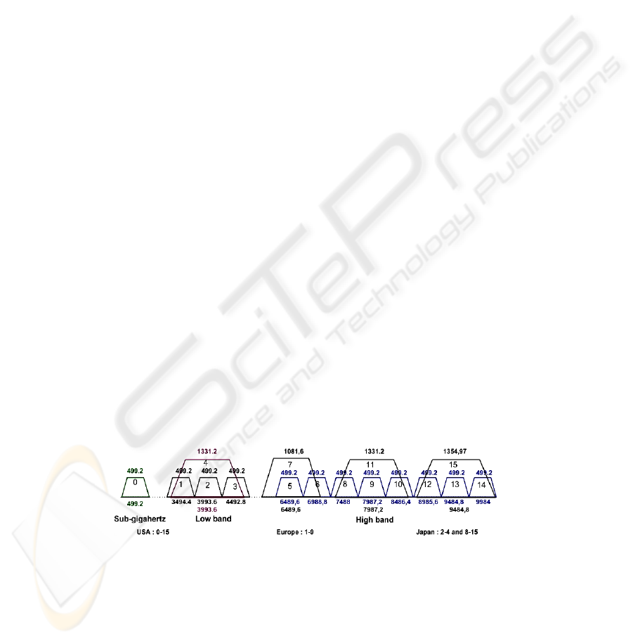
2.1 PHY Channels
According to the IEEE 802.15.4a standard, UWB devices can operate in three
independent bands: (1) the sub-gigahertz band (250–750 MHz), (2) the low band
(3.1–5 GHz) and (3) the high band (6–10.6 GHz). Fig. 1 gives the center frequencies
and bandwidths of the admissible bands, as well as the regulatory domains in which
they are admissible.
Fig. 1. IEEE 802.15.4a UWB plan bands.
The extremely wide bandwidth of UWB signals offers several advantages
including high data capacity, low probability of interception and interference, high
time resolution, low complexity, low power consumption, low cost and the co-
existence with other systems.
22

2.2 Frame Structures
Fig. 2.a and Fig. 2.b illustrate the UWB PHY frame with preamble sense based on the
Synchronization Header
(SHR) of a frame and the UWB PHY frame with preamble
sense based on the packet with the multiplexed preamble, respectively. The UWB
frame is composed of three major components: the SHR preamble, the PHY Header
(PHR), and the Physical layer Service Data Unit (PSDU).
Fig. 2. -a-IEEE 802.15.4a UWB frame structure. -b-IEEE 802.15.4a UWB frame with
multiplexed preamble.
2.3 Data Rates
For UWB PHY, the new standard defines several data rates including 110 kbps, 850
kbps, 6.81Mbps and 27.24Mbps and a variety of options that give IEEE 802.15.4a
compliant devices a high degree of flexibility. The data rate depends on the set of
PSDU rate-dependent parameters (bandwidth, preamble code length and modulation
and coding) and timing-related parameters (number of possible burst positions per
symbol and burst duration and symbol duration).In a Personal Area Network (PAN),
the network beacon broadcasts must be at the mandatory rate (850 kbps) for
synchronization reasons. Devices are allowed to use optional data rates when
communicating with each other, these rates are provided to allow devices in close
proximity to shorten their transmission duty cycle.
2.4 Power Consumption
The highest allowable limits for UWB emission are based on an equivalent emission
power spectral density (PSD) of – 41.3 dBm/MHz. A comparative study between the
energy consumption magnitude of the IEEE 802.15.4a standard and its original the
IEEE 80.215.4standard mentions that for the recent standard transmit powers cannot
exceed 37 μW and 96.3 μW respectively with 500 MHz and 1354 MHz of bandwidth,
where the majority of the original standard devices are expected to operate with
transmit powers between 0.5 mW and 10 mW, with 1 mW being the typical value.
Thus, power consumption is obviously much better in IEEE 802.15.4a UWB PHY
than IEEE 802.15.4 PHYs.
3 The Network Model
In general, BSNs are wireless networks that support the use of biomedical sensors and
23

are characterized by its (1) very low transmit power to coexist with other medical
equipments and provide efficient energy consumption, (2) high data rate to allow
applications with high QoS constraints,(3) low cost, low complexity and miniature
size to allow real feasibility.
These requirements are extremely hard to satisfy and are not met by known
elementary wireless network technologies. In order to satisfy those prominent
constraints and to deploy a very dense network supporting a considerable number of
BSNs, we propose a three-tiered network to represent the WHSN using UWB sensors.
In first and second layers of the network architecture, we have opted for the use of
UWB technology as a federating communication protocol to take advantage from its
extreme low transmit power minimizing interference and coping with health concerns,
high data rate allowing real-time and high data rate applications and location capacity
allowing mobility management and patient identification. As for the third tier, we
propose the use of WiFi technology to benefit from its high data rate, large coverage
and security aspect.
Fig. 3 shows all network layers composing the WHSN architecture:
1. First level (or lowest tier) represents the BSN,
2. Second level (or intermediate tier) represents the PAN,
3. Third level (or highest tier) represents the WiFi network.
Fig. 4 shows the proposed topology for each level of WHSN:
1. STAR topology for BSN given the simplicity of such topology,
2. Mesh topology for PAN in order to ensure energy efficiency, real-time
guarantees and Quality-of-Service (QoS),
3. Mesh topology for WiFi network in order to ensure real-time guarantees and
Quality-of-Service (QoS) in large coverage network.
3.1 First Tier: BSN
The first tier represents the BSN. As shown in the Fig. 5, we represent an elementary
BSN by a network with a surface of 2m by 2m (i.e. 4m²) ensuring the radio coverage
of the entire body network. Depending on the state of the patient, approximately
dozen of Impulse Radio UWB biosensors including the BSN coordinator can be
Fig. 3. WHSN architecture “three-tiered
cellular network”.
Fig. 4. Proposed topologies inside WHSN.
24
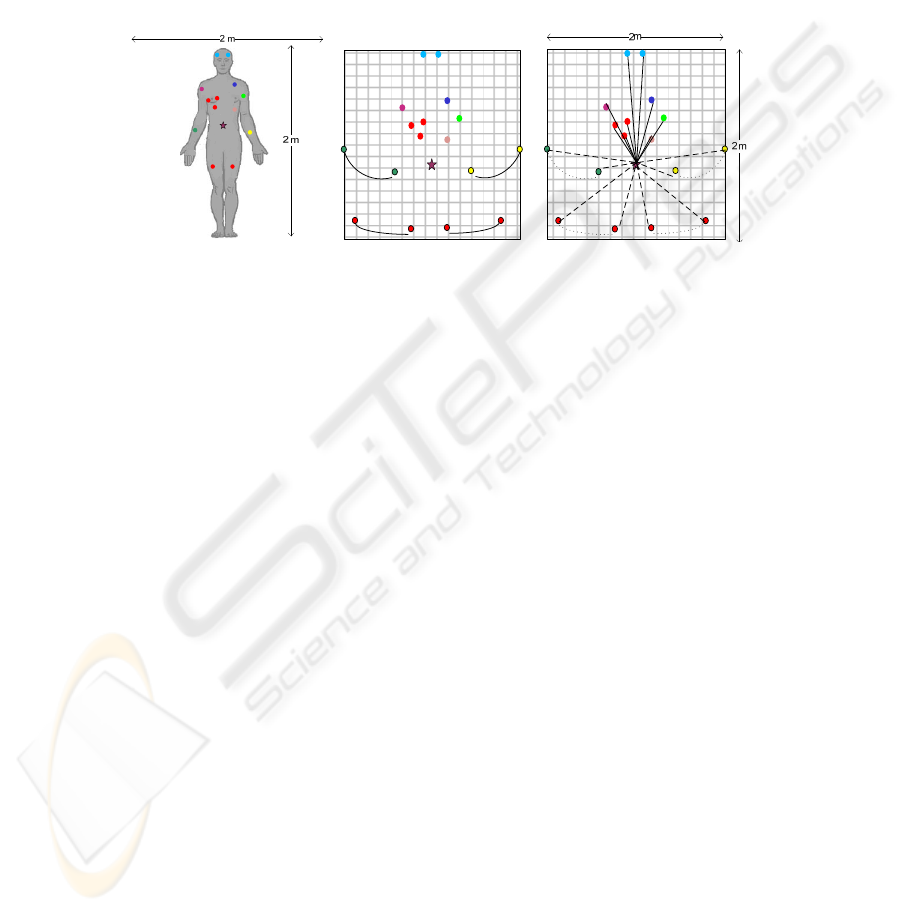
deployed at the most adequate locations in order to carry out the necessary
physiological information for patient health monitoring. Biosensor location, upon the
human body, is fixed and is defined according to the type of the biosensor. The BSN
coordinator, which is the BSN master node managing all BSN communications, must
be located at the center. As compared to its external environment, each BSN is
relatively mobile with regards to the others BSNs, routers and its PAN coordinator. In
addition, inside one BSN observe a quasi-mobility for biosensors located on the
hands, arms and feet.
The number and the type of biosensors vary from one patient to another depending
on the state of the patient. The most common types of biosensors are EEG
“Electroencephalography” to measure the electrical activity produced by the brain,
ECG “Electrocardiogram” to record the electrical activity of the heart over time,
EMG “Electromyography” to evaluate physiologic properties of muscles, Blood
pressure, Glucose monitor, heart rate, Thermometer, SpO2 “Oxymeter” to measure of
oxygen saturation in blood etc…
3.1.1 Topology
According to [13-14], Star, Mesh and Spanning Tree based topologies are applicable
to BSN. With regards to our BSN architecture, which supports IEEE 802.15.4a UWB
compliant sensors, the use of a star topology is the best choice, for the following
reasons. First, for a small centralised network of just 4 m
2
of scale, a star topology is
sufficient. Secondly, the star topology presents several advantages such as (1)
simplicity of deployment and management (2) low power consumption of biosensor
nodes (3) low latency and less need in terms of bandwidth (only one frequency
channel). In fact, there is no need to implement routing protocols in a star-based
network, which reduce the complexity of network. Devices or biosensors can only
exchange information with the BSN coordinator that might often be main-powered. In
our case, we admit that the BSN coordinator has less resource constraints than the
case of slave nodes. To avoid the “single point of failure” problem in the star
topology, we propose that the BSN support the use of a second coordinator. The BSN
switches from the first coordinator to the second coordinator only if the first former
fails or has a battery level lower than 50%. As illustrated in Fig. 6, in a BSN star
topology we distinguish two entities:
Fig. 5. Body Sensor Network organization.
25

1. The BSN Coordinator. It represents the coordinator of the network, which
is characterized by its single identifier. In other words, each patient is
identified by a unique identifier, in a network of patients. The BSN
Coordinator must ensure the following operations:
• Synchronization of the BSN network and with its PAN coordinator,
• GTS management according to the type of applications and the state of
patients,
• Duty cycle management within its BSN, according to the density of
biosensors per application, the type of application and the state of
patients,
• Data Routing of BSN physiological measurements toward PAN
coordinator of second network tier,
• Measurements for localization: A BSN coordinator periodically
performs measurements of localization in collaboration with the
routers of its vicinity,
• Update of allocated frequency channels used inside its own network
and the ones used for the routing of BSN physiological measurements
inside PAN,
• Priority scheduling to ensure the management of priority per service.
2. Slave Nodes (Biosensors). They must perform physiological measurements
and monitoring according to the underlying application (e.g. measurement of
the level of glucose in blood for the case of diabetic patient and the report of
alarms once the level exceeds the lower or higher limits).
3.1.2 Operational Mode
We propose the use of the beacon-enabled mode of the IEEE 802.15.4 protocol with
GTS (Guaranteed Time Slot) allocation to support real-time applications. Thus,
contrarily to Reference [15] that deployed the non beacon-enabled mode for their
BSNs based on IEEE 802.15.4a/CSS system, we consider that the beacon-enabled
mode is efficient in our model since we can use optional high data rates of 6 or 27
Mbps to shorten transmission delays and to satisfy application requirements without
compromising reliability.
In this mode, the BSN coordinator periodically broadcasts, at the mandatory rate of
850 kbps, beacon frames containing BSN information in order to synchronize its
associated devices and to identify its BSN.
During the superframe duration, two data transfer modes are permitted:
− Transfer from a Biosensor to the BSN Coordinator: a device willing to transfer
physiological information or alarm to the BSN coordinator uses slotted ALOHA
with the allocation of guaranteed time slots for the most critical information. The
BSN coordinator may confirm the successful data reception with an optional
acknowledgment message within the same Aloha slot.
− Transfer from the BSN Coordinator to a Biosensor: when the BSN coordinator has
pending data for a given device, it announces this information in beacon frames.
The interested device selects a free slot and sends a data request to the BSN
coordinator, indicating that it is ready to receive the data. The request is sent using
slotted ALOHA. When the BSN coordinator receives the data request message, it
selects a free slot and sends data using slotted ALOHA.
26

The choice of slotted ALOHA is done to avoid the additional access delay due to the
collision avoidance phase adopted in CSMA/CA mechanism given that BSNs
generally support light and medium traffic loads (very small collision probability).
3.1.3 Priority Scheduling
As detailed above, each biosensor must perform in a first step specific physiological
measurements and/or monitoring, and in a second step it must send to its BSN
coordinator these measurements, and if necessary, it reports alarms.
As shown in the Table 1, according to the characteristics of physiological
measurements or type of application services which can be Real-time or Non real-
time with High or Low rate, we classify the traffic into four services classes, where
class A is the most critical and D the less critical.
Table 1. Service Calssification of Physiological Measurements.
Type of Service Data rate Latency Class of Service
ECG High Low A Real-time high rate
EEG, EOG ,EMG Low Low B Real-time low rate
Heart rate, Blood pressure, Body
temperature, Glucose monitor
Low High C Non Real-time low rate
Medical image High High D Non Real-time high rate
During data communication period, biosensors transmit its data using the selected
data communication channel and with optional data rates of 6 or 27Mbps in order to
reduce communications delays. If a certain node has very urgent and critical data
(which requires reduced delays and high degree of reliability), in this case it requests
the allocation of one or several GTS time slots based on the traffic characteristics. The
allocation can be explicit by requesting a fixed number of time slots as specified in
the standard [16], or can be implicit by sending traffic specification to the BSN
coordinator, which will allocate slots accordingly as proposed in [17]. Else, the sensor
node can transmit its data without sensing the medium directly after a random time
slot units.
The GTS allocation is mainly dedicated to the most critical services, so BSN
coordinator must allocate such time slots by order of preference according to its
resource allocation scheduler. After receiving physiological information according to
its class of services, the BSN coordinator must be able to schedule its query in order
to facilitate the transmission of the most critical information. With an optimal priority
scheduling algorithm, we can reduce delays of critical information and satisfy QoS
requirements.
3.2 Second Tier: PAN
To improve patient’s network performance in a dense hospital environment, we
propose overlaying the network of BSNs with a second upper level network.
The hexagonal cell represents the PAN or the second network level. As shown in
Fig. 4 and Fig. 6, each PAN is represented by a cell of sensors organized in a mesh
topology including one PAN coordinator, several mobile BSN coordinators (one
27

active coordinator per BSN) and several routers which relay sensing information
toward PAN coordinator.
3.2.1 Topology
For a distributed processing, scalability, large coverage, medium complexity, load
balancing and energy consumption balancing that we propose mesh topology for the
second level of our network model. With such topology, multi-hop routing can
enhance significantly the energy consumption and thus maximize network lifespan by
balancing load and energy consumption over the entire network.
Fig. 6. PAN Organization.
As shown in the Fig.6 the network is divided into three entities:
1. PAN Coordinator, with double interfaces (Wifi/UWB), ensures:
• Synchronization of its network,
• Duty cycle management within its network, according to the density of
BSNs, routers and the state of patients,
• Management of time slots per channel allocation inside its cell [18]
according to spectrum resource and the priority of resource requests,
• Association and disassociation of BSNs,
• Data Routing: routing of the data of its cell and those of close cells,
• Priority scheduling per patient and service,
• Data security.
2. Routers: They represent fixed UWB sensors mainly acting as relays that
ensure:
• Data Routing and management of patients mobility and route update
within a cell,
• Executing some sensing measurements such as humidity, temperature
measurements inside the room where they are present.
3. PAN Slave Nodes: They represent BSNs coordinators.
3.2.2 Intra-Cell Routing
For routing inside a cell, we propose using geographic routing algorithm since routers
can dispose the location information of each BSN coordinator given that it supports
the UWB PHY ranging capability. To deal with energy efficiency/QoS paradox the
geographic routing can be optimized by balancing, on the one hand, load and energy
consumption all over the network and intelligently allowing routes according to the
class of priority of traffic flow, on the other hand.
28

3.2.3 Priority Scheduling
Each BSN represents on reality a patient network, so the state of the patient influences
the level of priority of data that it produces. As shown in table 2, according to the
state of patient and the characteristics of transmitted information, we classify the
traffic into 5 class of services, where class 1 is the most critical and 5 the less critical.
Table 2. Service classification of data inside PAN.
Level of critical state Latency Class of service/patient
High critical Low 1
Medium critical
A, B Low 2
C, D Medium
3
Less critical
A, B Medium
C, D High 4
Other information (location, temperature and
humidity)
Very High
5
3.2.4 Operational Mode
In [18], we have proposed a multi-channel MAC protocol for PANs to allow lower
latency operation and ensure high throughput without loss on reliability and to
maximize network lifespan. For more details, one can refer to multi-channel MAC
protocol given in [18].
3.3 Third Tier: Global WHSN
For efficient solutions in terms of energy saving, QoS supporting and mobility
management inside WHSN that cellular architecture, based on Wifi technology is
chosen for the third level to have on global a three-tier hierarchical cellular network.
The last tier represents the entire network, where the various entities are found:
• Sink: represents the central station that ensures collection, analysis and
treatment of the sensing measurements. We can propose more than one sink
according to number of medical data analysis centers.
• Cell Coordinator or PAN Coordinator: represents UWB/Wifi access points
which ensure data collection from patients and inter-cells routing.
• Intra-cell Routers: represent UWB sensors which ensure data routing and
some sensing measurements.
• BSN Coordinator and its Biosensors Members: represent UWB sensors that
ensure physiological measurements and medical monitoring.
As shown in Fig.7, our network represents a three-tier hierarchical cellular network.
For the inter-cell routing, we propose using mesh multi-hop routing, in order to
balance load of entire network. In addition, to deal with energy efficiency/QoS
paradox the inter-cell routing can be optimized in order to shorten end to end delays,
increase throughput and minimize and balance energy consumption.
29

Fig. 7.
Global Wireless Hospital Network.
4 Conclusions and Future Work
In this paper, we have firstly presented a survey of the UWB physical layer that has
recently been specified by the IEEE 802.15.4a standard, which represents a promising
candidate for future cyber-physical systems such as Body Sensor Networks and Home
Automation, etc. Then, we have proposed a new WHSN architecture in the form of a
UWB/Wifi based three-tiered network to take profit from the interesting features
offered by the IEEE 802.15.4a UWB physical layer. We believe that our proposed
network architecture for healthcare and medical applications in large-scale WHSNs
represents a very efficient solution for highly dense networks of patients, thus
avoiding congestion and sensors failure caused by energy inefficiency. On the other
hand, it ensures the improvement of the network performance in terms of energy
efficiency, real-time guarantees and Quality-of-Service (QoS).
Numerous perspectives for designing an optimal WHSN are possible via the proper
choice of IEEE 802.15.4a UWB PHY options and the best exploitation of its
advantages such as the adaptation of data rate according to the LQI, route selection
according to the traffic constraints, CCA mode selection according to application
requirements, etc. We are currently working towards the implementation of
simulation model of our WHSN architecture using OPNET simulator [19] to evaluate
its performance for different network scales (small, medium and large scales) to
evaluate the impacts of the number of patients in terms QoS energy consumption, and
real-time guarantees. In addition, we will propose an efficient channel allocation
mechanism for optimizing the use of radio channel in a large-scale WHSN.
30

References
1. IEEE 802.15.4a Standard (2007) Part 15.4: IEEE Standard for Information Technology,
Amendment to IEEE Std 802.15.4™-2006, (2007)
2. Tan, A.E.C., Chia, M.Y.W,: Measuring human body impulse response using UWB radar,
Electronics Letters, Vol. 41, Iss. 21, (2005) 1193 – 1194
3. Ryckaert, J., Desset, C., Fort, A., Badaroglu, M., De Heyn, V., Wambacq, P., Van
der Plas, G., Donnay, S., Van Poucke, B., Gyselinckx, B., : Ultra-Wide Band
Transmitter for Wireless Body Area Networks. IEEE Transactions on Circuits and Systems
I, Vol.52, No.12, (2005) 2515- 2525
4. Domenicali, D., Di Benedetto, M.-G.,:Performance Analysis for a Body Area Network
composed of IEEE 802.15.4a devices. The 4th Workshop on Positioning, Navigation and
Communication Hannover, Germany. (2007) 273-276
5. Yang-Sun, L., Jae-Min, K., Sung-Eon, C., Ji-Woong, K., Heau-Jo, K.,:A Study on the
Medical Image Transmission Service Based on IEEE 802.15.4a. Springer Berlin /
Heidelberg, (2007) 159-167
6. Kottapalli, V-A., Kiremidjian, A-S., Lynch, J-P., Carryer, E., Kenny, T-W., Law, K-H.,
Lei,Y., :Two-tiered wireless sensor network architecture for structural health monitoring.
10
th
Annual International Symposium on Smart Structures and Materials, USA (2003)
7. Bin, Z., Chao, H., HaiBin, W., Ruiwen G., Meng, M.Q-H., : A wireless Sensor Network for
Pervasive Medical Supervision. IEEE International Conference on Integration Technology,
Shenzhen, China (2007) 740-744
8. OTTO, C., Milenkovic, A., Sanders, C., Jovanov, E.,: System Architecture of A Wireless
Body Area Sensor Network For Ubiquitous Health Monitoring. Journal of Mobile
Multimedia, Vol. 1. No.4 (2006) 307-326
9. Milenkovic, A., OTTO, C., Jovanov, E.,: Wireless Sensor Network for Personal Health
Monitoring Issues and an Implementation. Computer Communications. Elsevier (2006)
10. She, H., Lu, Z., Jantsch, A., Zheng, L-R., Zhou, D., : A Network-based System
Architecture for Remote Medical Applications. Network Research Workshop (2007)
11. Hongliang, R., Meng, M-Q-H., Xijun, C.,: Physiological Information Acquisition through
Wireless Biomedical Sensor Networks. Hong Kong and Macau, China (2005) 483-488
12. Hongliang, R., Meng, M- Q-H., Xijun, C., Haibin, S., Bin, F.,Yawen, C., : System
Architecture of Body Area Network and Its Web Services Based Data Publishing. Springer
Berlin / Heidelberg. 947-954
13. Espina, J., Falck, T., Mülhens, O.,: Network Topologies, Communication Protocols, and
Standards. Spriger book. Body Sensor Networks 145-182
14. http://www.imec.be/wwwinter/mediacenter/en/SR2006/681579.htm
15. Bin, Z., Huan-Bang, L., Ryuji, K., : IEEE Body Area Networks for Medical Applications.
IEEE International Symposium on Wireless Communications Systems (2007) 327-331
16. IEEE 802.15.4 Standard Part 15.4: Wireless medium access control (MAC) and physical
layer (PHY) specifications for Low-Rate Wireless Personal Area Networks (LR-WPANs),
IEEE Standard for Information Technology, Revision of IEEE Std 802.15.4-2003, 2006.
17. Koubâa, A., Alves. M., Tovar. E., : i-GAME: An Implicit GTS Allocation Mechanism in
IEEE 802.15.4, In Euromicro Conference on Real-Time Systems (2006)
18. Ben Slimane, J., Song, Y-Q., Frikha, M., Koubâa, A.,:A multi-channel mac protocol for
wireless hospital sensor networks, Technical report, 2008, http://hal.inria.fr/inria-
00322584/fr/.
19. http://www.opnet.com/
31
