
USING
UML CLASS DIAGRAM AS A KNOWLEDGE
ENGINEERING TOOL
Thomas Raimbault, David Genest and St
´
ephane Loiseau
Leria laboratory − University of Angers, 2 boulevard Lavoisier, 49045 Angers Cedex 1, France
Keywords:
Knowledge Engineering, Model-Based Reasoning, UML, Conceptual Graphs, Visual Quering and Checking.
Abstract:
UML class diagram is the de facto standard, including in Knowledge Engineering, for modeling structural
knowledge of systems. Attaching importance to visual representation and based on a previous work, where
we have given a logical defined extension of UML class diagram to represent queries and constraints into the
UML visual environment, we present here how using the model of conceptuals graphs to answer queries and
to check constraints in concrete terms.
1 INTRODUCTION
In Knowledge Engineering (KE) several tools are
used, especially knowledge representation methods,
for knowledge modeling and processing; e.g. (Akker-
man et al., 2000). We consider both visual modeling
for human readability and capable processing by a
machine as fundamental in KE area. For these two
reasons, we advocate on the one hand the use of the
Unified Modeling Language (UML) as visual mod-
eler, on the other hand the use of the model of con-
ceptual graphs (CG) as engine reasoner.
Based on our previous work (Raimbault et al.,
2009), where we have given both an extension of
UML class diagram to represent queries and con-
straints into the UML visual environment and a first-
order logical (FOL) semantics for extended UML
class diagram (EUCD), we present here how using the
CG model to answer queries and to check constraints.
Due to the great deal in common between KE and
Software Engineering (SE) and the hight visual level
of UML class diagram as easy human readable mean-
ing, the integration of UML in KE becomes obvious;
e.g. (Rhem, 2006). UML − the so-called language
from SE − provides a way to software design by us-
ing diagrams of various kinds (Booch et al., 1998). In
this article, we focus our attention on class diagram
that is the main UML diagram and is used to model
structure of a system.
During the knowledge acquisition phase, the de-
signer needs to query and to check several parts of al-
ready represented knowledge to complete this phase.
However, UML is merely a language, then knowl-
edge is only represented as a drawing (no reasoning
way is available at the origin). The Object Constraint
Language (OMG, a) (OCL), which is an integral part
of UML 2, gives a solution to express constraints or
queries in addition to UML diagrammatic notations.
Nevertheless, as a textual language, OCL leaves the
visual interest of UML out. That is the main reason
why we use CG model to answer queries and to check
constraints rather than OCL tools (like USE (Gogolla
et al., 2007)).
In this paper, our contibution is to show how to
translate EUCD from (Raimbault et al., 2009) into the
CG model of (Chein and Mugnier, 1992; Chein et al.,
1998; Chein and Mugnier, 2004; Baget et al., 1999;
Baget and Mugnier, 2002). It is a knowledge rep-
resentation and calculation model with FOL seman-
tics that is implemented, for instance, in the Cogi-
tant platform (Genest, 2008). This translation is in-
teresting for tree reasons. First, the logical semantics
− called logical form − of EUCD (including query
and constraint) from (Raimbault et al., 2009) can eas-
ily mapped into the CG model using nested graphs
(Chein et al., 1998). Second, in the situation where
some element of a given class diagram can not be
represented in the visual environment of EUCD, the
CG model that provide a graphical environment (as
graph theory meaning) seems more preferable than
OCL that is a textual language. This second reason
also concerns the use of the CG model instead of
“classical” theorem prover because the visual repres-
ntation of CGs is more intuitive to use than logical
formulas. Third, Cogitant includes operators that can
e used to validate our work: queries and constraints
60
Raimbault T., Genest D. and Loiseau S. (2009).
USING UML CLASS DIAGRAM AS A KNOWLEDGE ENGINEERING TOOL.
In Proceedings of the 11th International Conference on Enterprise Information Systems - Artificial Intelligence and Decision Support Systems, pages
61-66
DOI: 10.5220/0001862400610066
Copyright
c
SciTePress
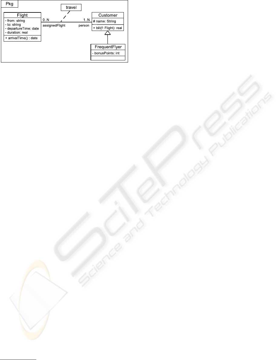
Figure 1: Example of a UML class diagram.
can be computed by this platform on EUCD.
This paper is organized as follows. Section 2 give
a short introduction to UML class diagram. Section 3
recalls recall the logical form of EUCD and the def-
inition of queries and constraints as kind of EUCD
from our previous works. Section 4 indicates how to
integrate EUCD into the model of conceptual graphs.
2 UML CLASS DIAGRAM
Class diagram shows statical structure of a system
with graphical notations. It describes the system’s
elements (especially classes), their features and their
relationships to other system’s elements. In a class
diagram, classes are modeled and are linked by two
types of relations: generalization and association.
Using the example in Figure 1, we briefly present
the main notations of a UML class diagram. A class
(e.g. Customer) is drawn as a solid-outline rectangle.
It contains the name of the class in the top compart-
ment, the attributes (e.g. name) in the middle compart-
ment, and the operations (e.g. bill) in the bottom com-
partment. This operation has one parameter, which is
an instance of the class Flight, and returns a data as
a real (primitive type). The generalization relation is
represented by an arrowed line drawn from the spe-
cialized class to the general class. Then, the class
FrequentFlyer has for generalization the Customer class,
and the Customer class has for subclasse the classe Fre-
quentFlyer. An association between the classes Flight
and Customer is defined
1
by the association class travel
and by the properties present at the ends of the associ-
ation, like the multiplicity 1..N or the role person. The
association class, which is a kind of class, is shown
as a class symbol (the top compartment is only rep-
resented here) linked by a dashed line to a line that
represent the association.
1
We have always chosen to represent an association as
its most complete form, i.e. by using an association class
(each association can be expended to an association class).
Note that we consider a UML class diagram as a
finite set of UML notations. We call a UML notation
a pair (concept, element), where concept is one of the
symbols that constitute the UML class diagram lan-
guage, and element is an instance of this concept. For
example, in Figure 1 Flight is an element of the con-
cept ‘class’. We divide concepts in three sets: the set
of entities, the set of relations and the set of proper-
ties. An entity is used to refer to general concepts such
as: class, attribute, operation, etc. A relation is either
a generalization or an association between classes. A
property provides more precisely a meaning, like vis-
ibility or multiplicity.
3 PREVIOUS WORKS
The presented work in this paper is based on our pre-
vious works (Raimbault et al., ) and (Raimbault et al.,
2009). In (Raimbault et al., ) is proposed a first way
for querying and checking UML class diagram by us-
ing the model of conceptual graphs. (Raimbault et al.,
2009) gives a simplification and an explicit formaliza-
tion in FOL of the implicit logical semantics using in
(Raimbault et al., ) to transforme class diagrams into
conceptual graphs.
We now recall the main contributions from (Raim-
bault et al., 2009): logical form of a class diagram,
an extension of class diagram with variables and bi-
coloration, and query and constraints.
3.1 Logical Form of UML Class
Diagram
In our previous work (Raimbault et al., 2009), we as-
sociate a FOL semantics, called Logical Form (LF),
of a given UML class diagram. The predicat set that
are used expresses the UML meta-model (OMG, c).
In a class diagram, an element may be described
by some others: these other elements are enclosed
into it. For instance, a class is described by its at-
tributes and its operations, which are nested into the
class representation. We call the entity that encloses
the others the context of them. In light of those ob-
servation and rather than other approaches to trans-
forme UML class diagram into FOL formula − e.g.
(Beckert et al., 2002) −, in our approach a predicate
that represents an entity (respectiveley a relation or a
property) is a binary predicate (respectiveley a ternary
predicate): the first one argument is used to represent
the context of an element.
Logical Form. The Logical Form Φ
D
of a UML
class diagram D is a FOL formula of conjunction of
USING UML CLASS DIAGRAM AS A KNOWLEDGE ENGINEERING TOOL
61
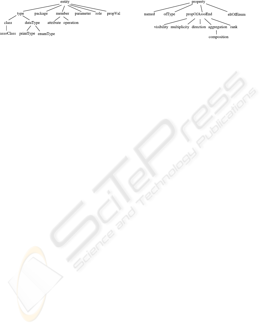
Figure 2: Entity set of UML class diagram meta-model.
predicates. A predicate in Φ
D
represents a concept
of the UML class diagram language (i.e. UML class
diagram meta-level). A constant in Φ
D
refers to an el-
ement of D (i.e. an instance of a concept). According
to different kind of UML notations that can be used in
D, Φ
D
is obtained as follows:
• an instance e of an entity E is repesented by the
binary predicate E(c
e
, id
e
) where c
e
is the context
of e and id
e
is the identifier of e (see Φ
1
as exam-
ple). The entity predicate set is partially ordered
in Figure 2.
• a generalization link between the more gen-
eral class C
1
and the more specific class C
2
is
repesented by the ternary predicate generaliza-
tion(c
g
, id
c
1
, id
c
2
) where c
g
is the context of the
generalization link, id
c
1
and id
c
2
are respectively
the identifiers of C
1
and C
2
(see Φ
2
as example).
• a association link among classes C
1
, . . . , C
n
is - in
UML - a group of several association ends. The
associtaion link, strictly speaking, is represented
as an association class, i.e. an instance of the
entity assoClass (see first item); The i
th
associa-
tion end is repesented by the ternary predicate as-
soEnd(c
a
, id
c
i
, id
r
i
) where c
a
is the context of the
association link, id
c
i
is the identifier of class C
i
and id
r
i
is the identifier of role that is associated
to C
i
according to this association link; The group
is composed by the use of the ternary predicate
association(c
a
, id
a
, id
r
i
) where id
a
is the identifier
of the association link (i.e. the association class);
(see Φ
3
as example).
• a value v for the property P that is applied to an
entity or a relation a is repesented by the ternary
predicate P(c
a
, id
a
, v) where c
a
is the context of a
and id
a
is the identifier of a (see Φ as example).
The property predicate set is partially ordered in
Figure 3.
Example: Φ
1
is the LF of the part of class diagram in
Figure 1 amount to the class Customer, Φ
2
is the LF of
the generalization link between FrequentFlyer and Cus-
tomer, Φ
3
is the LF of the association travel. Finally, Φ
is the LF of class diagram in Figure 1, based on par-
tial LFs Φ
1
to Φ
3
that are competed w.r.t. appropriate
properties.
Figure 3: Property set of UML class diagram meta-model.
Φ
1
= package(>, pkg) ∧ class(pkg, customer) ∧ at-
tribute(customer, name) ∧ operation(customer, bill) ∧
parameter(bill, f).
Φ
2
= generalization(pkg, customer, frequentflyer).
Φ
3
= assoClass(pkg, travel) ∧ role(pkg, assigflight) ∧
role(pkg, person) ∧ assoEnd(pkg, flight, assigflight)
∧ assoEnd(pkg, customer, person) ∧ association(pkg,
travel, assigflight) ∧ association(pkg, travel, person).
Φ = Φ
1
∧ named(pkg, customer, ”Customer”) ∧
propVal(pkg, ”Customer”) ∧ ofType(bill, f, flight) ∧
. . . ∧ Φ
2
∧ Φ
3
∧ multiplicity(pkg, person, 1-N) ∧ . . . .
First, note that the more general context is repre-
sented by the constant >. Second, note that each ele-
ment is identified by a constant: for visibility reasons,
in our example an identifier is the element’s name pre-
fixed by its full context (but identifiers may be num-
bers as id
1
, id
2
, etc.). Third, note that named is a prop-
erty that makes the link between an identifier of an
entity and its real name in a class diagram. Fourth,
note that predicate propVal is used to define a prop-
erty’s value as an entity itself.
3.2 Querying and Checking EUCD
In (Raimbault et al., 2009), we have proposed an ex-
tension of UML class diagram, called extended UML
class diagram (EUCD), using variables and/or bi-
coloration. Then, we have defind two family of ex-
tended UML class diagrams: queries and constraints.
Queries are used to find some elements, and con-
straints to check some other. We recall in this section
how to query and check UML class diagram.
Variable and Mapping. Any element in a EUCD
can be a variable. It seems that the element exists
whereas it is not identified (a temporary identifier is
used: the variable’s name). The new visual notation
associated of a variable x is denoted in EUCD D by
the symbol $x. In Φ
D
, the existential quantified vari-
able x is used.
A mapping from a EUCD D
1
to a EUCD D
2
is a min-
imal subset D
0
2
of D
2
such as knowledge modeled by
D
1
can be infered by knowledge modeled by D
0
2
.
ICEIS 2009 - International Conference on Enterprise Information Systems
62
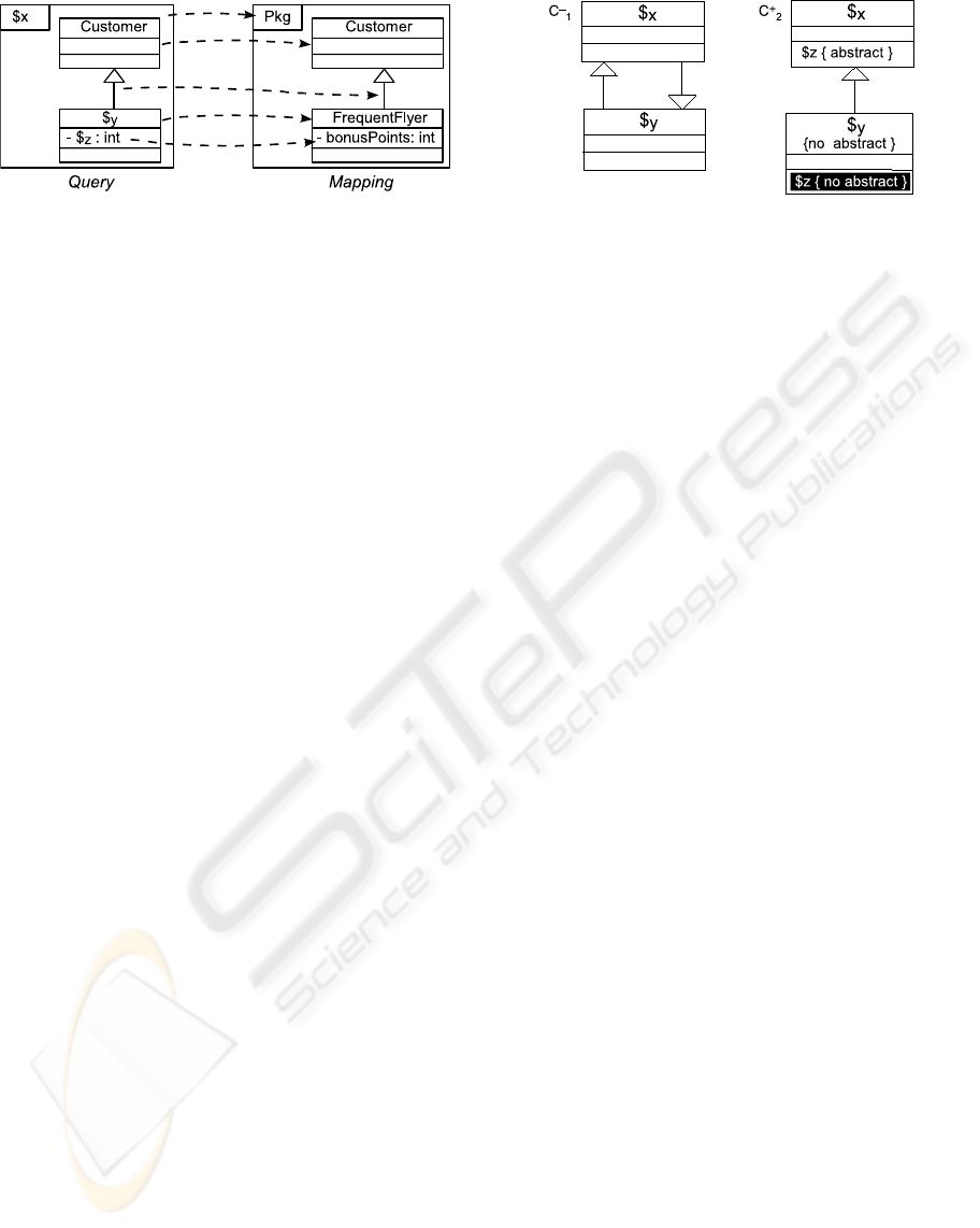
Figure 4: A UML query and a mapping.
Querying UML Class Diagram. A query is a
EUCD (see left part of Figure 4 for instance). The
result(s) of a query Q to interrogate a EUCD D is the
set of mappings from Q to D.
Example: The query in Figure 4 expresses the
fact that “In a given package, does a class
named Customer has a subclass that has an at-
tribute of type int?”. The LF of this query
is: Φ
Q
= ∃x,y,z package(>,x) ∧ class(x,id
1
)
∧ named(x,id
1
,”Person”) ∧ propVal(x,”Person”) ∧
class(x,y) ∧ generalization(x,id
1
,y) ∧ attribute(y,z)
∧ visibility(y,z,”private”) ∧ propVal(>,”private”) ∧
ofType(y,z,int) ∧ primType(>,int).
The answer of this query to interrogate class diagram
on Figure 1 is presented on the right side in Figure 4.
One can see that the intended class is Frequentflyer:
into package Pkg and with the attribute bonusPoints.
Checking UML Class Diagram. Two kind of con-
straints are defined: negative and positive constraints.
A negative constraint C
−
expresses a specification
like “no A exists” in a class diagram D: no mapping
from C
−
to D must be found. A negative constraint
is represented by a EUCD. A positive constraint
C
+
expresses a specification like “if premise A,
then obligation B”. In other words, if a mapping
from the premise of C
+
to a class diagram D (which
has to be check by C
+
) exists, then this mapping
must be extend from whole C
+
to D. A positive
constraint is represented by a EUCD where premise
is white background colored and obligation is black
background colored.
Example: Figure 5 shows a negative constraints C
−
1
and a positive constraints C
+
2
. C
−
1
expresses the fol-
lowing prohibition: “a class X can be a subclass of
a class Y, which is a subclass of X”. In other words,
this constraint checks that “there is no simple inheri-
tance cycle”. C
+
2
expresses the following obligation:
“if a class X has an abstract operation z, for each sub-
class Y of X that is non-abstract, z must necessarily be
overwritten as a non-abstract operation”.
Figure 5: UML negative and positive constraints.
According to constraints C
−
1
and C
+
2
, the class dia-
gram in Figure 1 is valid.
4 INTREGRATION INTO
CONCEPTUAL GRAPHS
In this article, we use the CG model from (Chein
and Mugnier, 1992) with nested graphs (Chein and
Mugnier, 1997; Chein et al., 1998), coreference links
(Chein and Mugnier, 2004) and constraints (Baget
et al., 1999; Baget and Mugnier, 2002). This CG
model presents many interests. It is a formal and vi-
sual knowledge representation model. It provides a
reasoning operator, called projection, which is sound
and complete with respect to deduction in FOL (see
(Sowa, 1984; Chein and Mugnier, 1992) for simple
graphs, (Chein et al., 1998) for nested graphs. We use
the CG model instead of “classical” theorem prover
because in case of necessity to represent some knowl-
edge that can not be represented in UML, the visual
aspect of the CG model is more intuitive to use than
logical formulas.
4.1 A Short Introduction to CGs
In the CG model, a support specifies the vocabu-
lary representing ontological knowledge. It describes
available concept and relation types ordered by a spe-
cialization relation. Facts are represented by con-
ceptual graphs, which nodes represent individual in-
stances of concepts and relations between them. The
fundamental reasoning operation is a graph morphism
called projection. It induces a subsumption relation
between graphs.
Support. We consider here a support
S = (T
C
, T
R
, I). T
C
is a partially ordered set of
concept types whose greatest element is >. T
R
is a
partially ordered set of relation types. For the paper,
we only use binary relations whose greatest element
is >
2
(but in general relations may be of any arity
greater or equal to one). Each relation type has a
USING UML CLASS DIAGRAM AS A KNOWLEDGE ENGINEERING TOOL
63
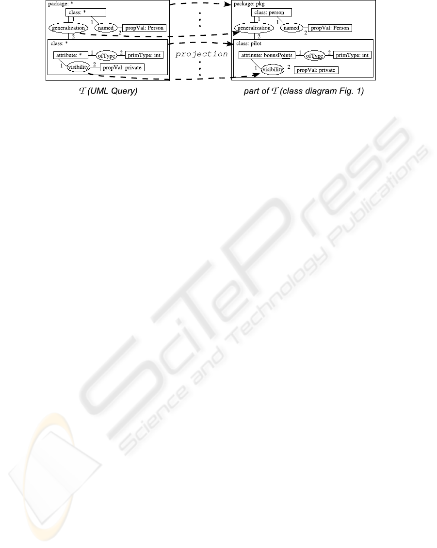
Figure 6: T(UML query) and projection from it to T(class diagram Fig.1).
signature, which gives the greatest possible concept
type for each argument. I is a countably infinite set
of individual markers.
Nested Conceptual Graphs. A nested conceptual
graph (NCG), related to a support S, is a bipartite la-
belled multigraph G = (C, R, E, l). C is the set of con-
cept nodes, R the set of relation nodes, and E the set
of edges.. Each label is given by the mapping l. The
label of a relation node is a relation type from T
R
. The
label of a concept node is composed of a concept type
from T
C
, a marker from I ∪ {∗} (if ∗, the node repre-
sents a generic individual, else a specific individual)
and a description, which may be either sets of NCG
or empty (refered by ∗∗ in (Chein and Mugnier, 1997;
Chein et al., 1998)). For a graph G, which is in a de-
scription of a concept node c of another graph, one
saids that G is nested into c. Labels on concept nodes
must respect the signature defined for their relation
neighbors. Every edge is labeled by 1 or 2 (in the
case of binary relations), for indicating which is the
first and the second argument of each relation node.
4.2 EUCD into the CG Model
We first show how to translate an extended UML class
diagram (EUCD) into a CG: the ordered sets of UML
concepts are defined in a support of CGs; the transla-
tion of a given UML class diagram in a nested CG is
presented (see (Raimbault et al., ) for details). Sec-
ond, we describe how to translate queries and con-
straints into the CG model. Once we have it, we use
the projection operator for making reasoning (query-
ing and checking).
4.2.1 LF and Nested Conceptual Graphs
Proposition 1 (EUCD into CG). A EUCD can be
translated into a nested CG.
UML concepts are translated into a support S. A
EUCD is translated into a nested CG based on S. We
define S = (T
C
, T
R
, I) as follows:
• The set of concept types T
C
is the set of entity
predicates (Figure 2). Then the partial order be-
tween concept types is the partial order between
entities, i.e. entity is the greatest concept type.
• The set of relation types T
R
is composed of the
set of property predicates (Figure 3) in accordance
with partial order between them, plus the pred-
icates generalization, assoEnd and association.
Property, generalization, assoEnd and associa-
tion have a greater common relation type >
2
.
• The set of individual markers I is the set of iden-
tifiers of elements.
Let D be a EUCD, we build a nested CG T(D) based
on S such as by construction the FOL formula of T(D)
(Chein and Mugnier, 1997; Chein et al., 1998; Chein
and Mugnier, 2004) is equivalent to Φ
D
. T(D) is the
nested CG NCG(D, >), which is recursively defined
by NCG(D, c) as follows:
• For each P(c, t
1
) ∈ Φ
D
, a new concept node C
t
1
is
created. C
t
1
is labelled by (type, marker, descrip-
tion); type is P; marker is either t
1
if t
1
is a con-
stant or ∗ if t
1
is a variable; description is either
NCG(D, t
1
) if NCG(D, t
1
) is not empty or ∗∗.
• For each P(c, t
1
, t
2
) ∈ Φ
D
, a new relation node is
created between C
t
1
and C
t
2
. This relation node is
labelled by P.
After this translation, coreference links are created
between concept nodes C
x
for each variable x of Φ
D
.
4.2.2 Queries and Constraints
Proposition 2 (UML Query and Projection). Let D
be a UML class diagram and Q a EUCD. There is
a mapping from Q to D iff there is a projection from
T(Q) to T(D).
Example: Figure 6 presents in the CG model the ex-
ample on Figure 4: on the left side is the translated
CG T(UML query), on the right side a part of the
translated CG T(class diagram Fig. 1). The projection
from T(UML query) to T(class diagram Fig. 1) is the
ICEIS 2009 - International Conference on Enterprise Information Systems
64

application from the labelled nodes of T (UML query)
into labelled nodes of T(class diagram Fig. 1) that
may decrease node labels (Chein and Mugnier, 1997;
Chein et al., 1998; Chein and Mugnier, 2004). A con-
cept node is represented by a rectangle [typeConcept:
individualMarker] or [typeConcept: ∗] that may have
a nested CG into it; a relation node is represented by
an oval (relationConcept).
Proposition 3 (UML Constraint and CG Con-
straint). A UML positive constraint (resp. negative
constraint) is translated into a CG positive constraint
(resp. CG negative constraint)
2
by T that is extended
such as the coloration is preserved (resp. each node
is one colored.).
Let D be a UML class diagram and C a UML con-
straint. D verifies C iff T(D) verifies (Baget et al.,
1999; Baget and Mugnier, 2002) T(C).
A prototype was developed to make an interface
between a EUCD and a CG by using Cogitant (Gen-
est, 2008). It translates UML class diagram, UML
query and UML constraint into CGs. Cogitant opera-
tors (based on projection) compute results of queries
and verifie constraints on CGs. This interface makes
the visual link between CGs and UML class diagram
to display results computed by Cogitant (Raimbault
et al., ) on UML class diagram.
5 FUTURE WORK
We have proposed a way to translate UML queries
and UML constraints − both as EUCD − into the CG
model, and so use projection to query and check class
diagram. By using inverse translation, results can be
displayed in the visual representation of UML.
Due to the importance of visual representation of
knowledge, see for instance (OMG, b; Lukichev and
Wagner, 2006), we will now focus our attention on
how to represent rules into the UML visual environ-
ment by using bi-coloration (white background for
head and black background for conclusion) and how
to infere them by using the CG model.
REFERENCES
Akkerman, H., Anjewierden, A., Hoog, R. D., Shad-
bolt, N., de Welde, W. V., and Wielenga, B. (2000).
Knowledge engineering and management: the Com-
monKads methodology. Cambridge, MIT Press.
2
We recall that a CG constraint is a colored CG (Baget
et al., 1999; Baget and Mugnier, 2002).
Baget, J., Genest, D., and Mugnier, M. (1999). Knowl-
edge Acquisition with a Pure Graph-Based Knowl-
edge Representation Model. In Proc. of KAW’99, vol-
ume 2, pages 7.1.1–7.1.20.
Baget, J. and Mugnier, M. (2002). Extensions of Sim-
ple Conceptual Graphs: the Complexity of Rules and
Constraints. JAIR, 16(12):425–465.
Beckert, B., Keller, U., and Schmitt, P. H. (2002). Translat-
ing the Object Constraint Language into First-order
Predicate Logic. In Proc.of VERIFY, Workshop at
FLoC’02.
Booch, G., Jacobson, C., and Rumbaugh, J. (1998). The
Unified Modeling Language - a reference manual. Ad-
dison Wesley.
Chein, M. and Mugnier, M. (1992). Conceptual Graphs:
Fundamental Notions. Revue d’intelligence artifi-
cielle, 6(4):365–406.
Chein, M. and Mugnier, M. (1997). Positive nested con-
ceptual graphs. In Proc. of ICCS’97, volume 1257 of
LNAI, pages 95–109. Springer.
Chein, M. and Mugnier, M. (2004). Concept types and
coreference in simple conceptual graphs. In Proc. of
ICCS’04, volume 3127 of LNAI. Springer.
Chein, M., Mugnier, M., and Simonet, G. (1998). Nested
Graphs: A Graph-based Knowledge Representation
Model with FOL Semantics. In Proc. of KR’98, pages
524–534. Morgan Kaufmann Publishers.
Genest, D. (2008). Cogitant Reference Manual, version
5.1.92. http://cogitant.sourceforge.net.
Gogolla, M., Bttner, F., and Richters, M. (2007). USE: A
UML-Based Specification Environment for Validating
UML and OCL. Science of Computer Programming,
69:27–34.
Lukichev, S. and Wagner, G. (2006). Visual Rules Model-
ing. In Proc. of ICPSI’06. Springer.
OMG. Object Constraint Language, Version 2.0.
http://www.omg.org/spec/OCL/2.0/.
OMG. Production rule representation. Technical report.
br/2003-09-03.
OMG. Specification for the UML 2 modeling language.
http://www.omg.org/spec/UML/2.1.2/.
Raimbault, T., Genest, D., and Loiseau, S. A New Method
to Interrogate and Check UML Class Diagrams. In
Proc. of ICCS’05. Springer.
Raimbault, T., Genest, D., and Loiseau, S. (2009). A useful
logical semantics of UML for querying and checking
UML class diagram. In Proc. of ICAART’09, pages
179–184. Insticc Press.
Rhem, A. J. (2006). UML for Developing Knowledge Man-
agement Systems. New York, Auerbach Publications.
Sowa, J. (1984). Conceptual Structures: Information Pro-
cessing in Mind and Machine. Addison Wesley.
USING UML CLASS DIAGRAM AS A KNOWLEDGE ENGINEERING TOOL
65
