
AN APPROACH TO MODEL-DRIVEN DEVELOPMENT
PROCESS SPECIFICATION
Rita Suzana Pitangueira Maciel
1,2
1
Universidade do Estado da Bahia, Salvador, Brazil
Bruno Carreiro da Silva, Ana Patrícia Fontes Magalhães
2
Faculdade Ruy Barbosa, Salvador, Brazil
Nelson Souto Rosa
Centro de Informática, Universidade Federal de Pernambuco, Recife, Brazil
Keywords: MDA, MDD, Process Specification, SPEM.
Abstract: The adoption of MDA in software development is increasing and is widely recognized as an important
approach for building software systems. Meanwhile, the use of MDA requires the definition of a software
process that guides developers in the elaboration and generation of models. While first model-driven
software processes have started to appear, an approach for describing them in such way that they may be
better communicated, understood, reused and evolved systematically by the development team is lacking. In
this context, this paper presents an approach for the specification of MDA processes based on
specializations of some SPEM 2 concepts. In order to support and evaluate our approach a tool was
developed and applied in a particular MDA process for specific middleware services development.
1 INTRODUCTION
The Model Driven Engineering (MDE) is an
approach specially focused on modelling techniques,
alleviating the complexity of platforms and
expressing domain concepts effectively (Schmidt
2006). MDE advocates that the models of a software
system are not only used for documentation, but they
actually serve as basis for the implementation phase.
Each activity of the development process requires a
number of input models that produce further models
as output. In this way, the development of an
application is viewed as a set of transformations that
lead to the final system.
One of the most well known initiatives in this
scenario is the Model-Driven Architecture (MDA)
[OMG 2003]. MDA separates subject matters so that
application-oriented models are independently
reusable across multiple implementations and vice
versa through the construction of three categories of
models (CIM – Computational Independent Model,
PIM – Platform Independent Model and PSM –
Platform Specific Model). Current MDA supporting
tools are particularly interested in defining
transformations that produce code and deployment
artefacts from design models (e.g. AndroMDA
1
,
oAW
2
, etc.). Another research direction in the MDA
context is the definition of software development
processes for specific domains (Maciel 2006a),
(Koch, 2006).
The description of a software process is called
process model. A process model can be expressed
through any specific language or notation which is
called Process Modeling Language (PML). A
process model can be enacted when a development
team follows the process model during the
development life cycle. The use of MDA requires
the definition of a software process that guides
developers in the elaboration and generation of
software models (Mellor 2004). In addition to well-
1
http://www.andromda.org
2
http://www.openarchitectureware.org/
27
Pitangueira Maciel R., Carreiro da Silva B., Fontes Magalhães A. and Souto Rosa N. (2009).
AN APPROACH TO MODEL-DRIVEN DEVELOPMENT PROCESS SPECIFICATION.
In Proceedings of the 11th International Conference on Enterprise Information Systems - Information Systems Analysis and Specification, pages 27-32
DOI: 10.5220/0001862700270032
Copyright
c
SciTePress

known processes such as RUP, XP, OSDP, etc., an
MDA process requires the selection of metamodels
and mapping rules for the generation of the
transformation chain that produces models and
application code (Maciel 2006a).
Several MDA processes have been proposed
such as for Middleware Services (Maciel 2006a),
Web Applications (Koch 2006), E-learning (Wang
2003) and a version of the Open Unified Process for
MDD (OpenUP 2008). However, there is a lack of
consistent terminology since there is no unified
language to specify MDA processes: each one
adopts ad hoc notations and different concepts are
used to define the activities and artefacts for the
software development life cycle. The software
process modelling through the use of a unified and
consistent terminology should make communication,
understanding, reutilization, evolution, management
and standardization of the process possible
[Humprey 1989].
PMLs, such as SPEM (Software Process
Engeneering Metamodel Specification) (OMG 2008)
and E
3
language (Jaccheri 1999) were proposed in
recent years but they do not focus specifically on
MDA processes.
This paper presents an approach to MDA process
specification based on the SPEM 2 standard
concepts. Our work defines an approach and a
supporting tool which can be used to instantiate an
MDA process for a given domain. Using this
approach, developers can describe the steps and
associate artefacts to perform MDA modelling and
transformation chain.
There is a specific process called OpenUP/MDD
(OpenUP 2008) built on Eclipse Process
Framework
3
(EPF) which focuses specially on the
model driven development. However, the
OpenUP/MDD is a process instance of the SPEM
metamodel concepts, while our approach is placed at
a higher abstraction level. We address the MDA
process concepts at the metamodel level.
Consequently, we provide a more flexible and
extensible way to model and specify (instantiate)
model driven software processes according to SPEM
2 and MDA standards.
Bendraou et al. (2007) proposed an extension to
the SPEM 2.0 specification, called xSPEM, in order
to allow process enactment. Although their work
targets the enactment of process models they don’t
focus particularly on the process modelling or
enactment of MDA development process.
3
http://www.eclipse.org/epf/
The rest of this paper is organized as follows:
section 2 presents the basic principles about the
SPEM and MDA standards; section 3 describes the
approach to model-driven development process
specification; section 4 shows a case study prepared
in order to evaluate the proposed approach; the
related work is discussed on section 5; section 6
makes some final remarks and proposes future work.
2 OVERVIEW OF SPEM AND
MDA CONCEPTS
MDA is an OMG standard aiming at facilitating
MDD (Model-Driven Development). Metamodels
define an abstract syntax for modelling languages.
Models should be instances of some metamodel,
following its syntactic and semantic specification,
that is, they should be written according to the
corresponding metamodel of the modelling
language.
Using the MDA approach, models and
metamodels are expressed through the Unified
Modeling Language (UML). The UML lightweight
extension mechanism, also known as UML profile
mechanism, is used to extend the metamodel
elements using stereotypes and tagged values.
Model transformation languages are used to
specify how source metamodel elements are
transformed into target metamodel elements; CIM to
PIM, PIM to PSM, are examples of transformation.
Transformations may be automatic, semi-automatic
and manual. We also can have transformations from
model to code in addition to model to model.
SPEM 2 (OMG 2008) defines a metamodel
based on MOF and a UML profile, specified by
OMG and used to define software process and their
components. According to SPEM 2 it is possible to
create a knowledge base independent of any process,
using elements such as Packages, Roles, Tasks,
WorkProducts and Disciplines (from the method
content package) to reuse in the specification of
many different processes. A Process has a sequence
of Phases expressing the life cycle of a product
under development. It represents a significant period
in a project, ending with major management
checkpoint, milestone or set of deliverables.
For
each Phase there might be at least one Iteration that
groups a set of pieces of work that are repeated more
than once. It represents an important structuring
element to organize work in repetitive cycles.
ICEIS 2009 - International Conference on Enterprise Information Systems
28
3 MDA PROCESS
SPECIFICATION
The use of MDA requires process definitions
associated to modeling activities and transformation
rules to compose the transformation chain. These
elements are not usually found in software
development processes. Therefore an approach was
specified covering these aspects.
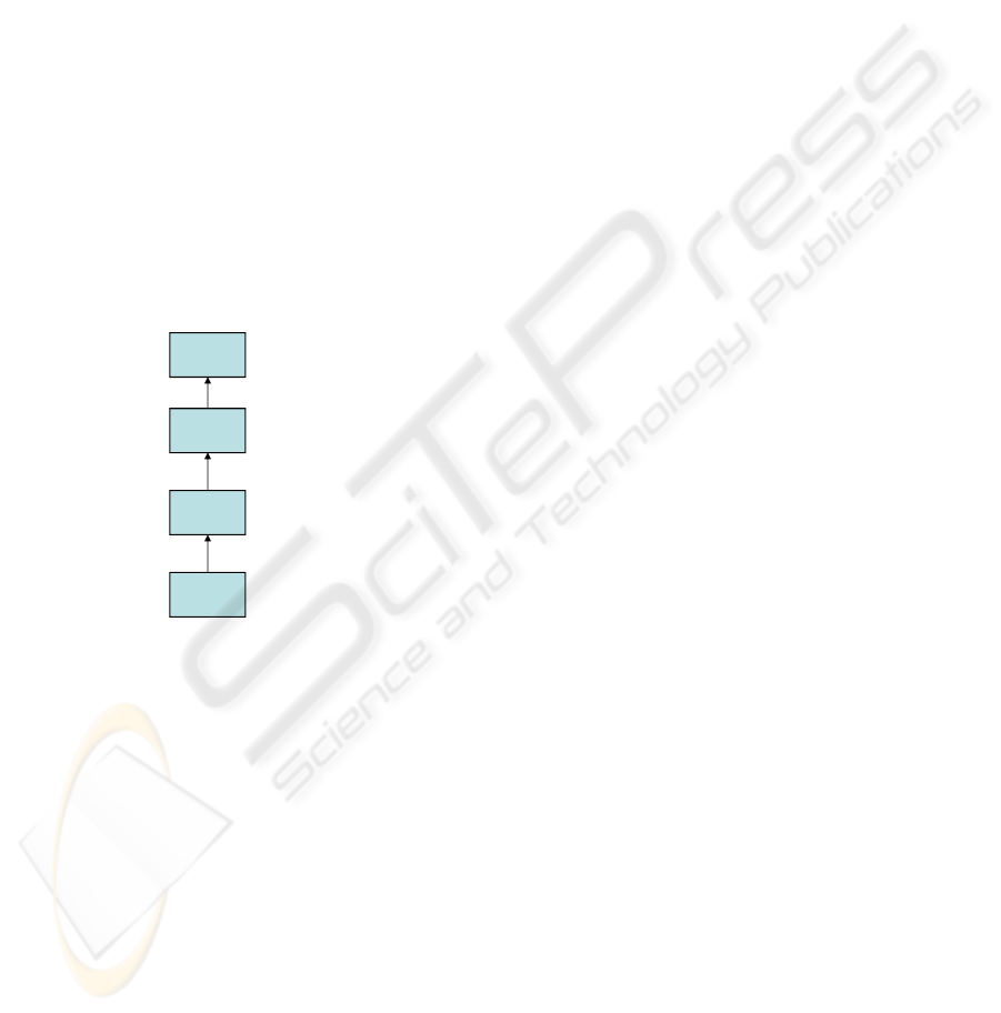
OMG suggests model layers to represent a
process and their meta languages (Figure 1). As can
be seen, our approach is situated at level M2 (meta
model level). Based on it, any MDA process model
(located in level M1), can be specified and will be
available to be used on the development of new
projects in level M0. The proposed approach
includes the following elements: (1) SPEM
metamodel slice with a specialization of some
concepts according to MDA; (2) indication of a set
of diagrams for modelling method content and
processes.
MOF
SPEM, UML,
MDA process meta model
RUP, XP
MDA Process
Specific Project
Meta Meta model level
Meta model level
Process model level
Process development level
M0
M1
M2
M3
Figure 1: OMG model layers (adapted from (OMG 2008)).
3.1 Metamodel and Diagrams
Our approach is based on the metamodel illustrated
in Figure 1. This metamodel extends some of the
SPEM 2 concepts specializing them for the MDA
context.
The process specification needs static and
reusable definitions such as Disciplines, Tasks,
Roles and WorkProducts (from the method content
package in Figure 2). A Role defines a set of related
skills, competencies and responsibilities of an
individual or a set of individuals. Individuals should
play their Roles performing Tasks that can be
associated to input and output WorkProducts. A
Task may comprise many Steps to describe a
meaningful and consistent part of the overall work.
The Discipline represents a collection of Tasks that
are related to a major ‘area of concern’ within the
overall project. WorkProducts are in most cases
tangible artefacts consumed, produced, or modified
by Tasks.
In our approach, the WorkProduct is specialized
into four kinds of artefacts: UMLModel, produced
by a process role or automatically generated by a
transformation during the process execution;
TransformationRule contains the rules for model
transformation and code generation during the
process execution; ExtraModel, used only for
documentation and are based on text or
supplementary notations; and Profile to represent an
UML profile to base the UML modelling on each
phase. Transformation rules are used in MDA
process to automatically transform UML models.
Each transformation rule should refer to at least one
source model and generate one or more target
models. Based on the above definitions, the MDA
process structure is specified according to the
metamodel shown in the second part of Figure 1. As
illustrated, a Process has a life cycle composed of a
set of sequential Phases performed in Iterations. In
terms of MDA, these phases represent the modelling
of CIM, PIM, PSM and Codification. Each
Modelling Phase is associated to a UML profile
defined to address specific characteristics of a
particular domain or platform.
Based on the metamodel presented in Figure 1,
the MDA process should be specified by the
construction of three kinds of UML diagrams: class,
use case and activity diagrams.
Table 1 presents the SPEM 2 stereotypes (second
column) extended in our metamodel and their usage
in the three indicated UML diagrams (first column).
The third column refers to the UML base element
according to each SPEM stereotype. For example, in
a use case diagram Tasks are modelled as use cases,
while in the activity diagram they are modelled as
action states.
In this case, the class diagrams are used to
specify the elements of a knowledge base (method
content) and the process life cycle overall static
structure. This is the first diagram that should be
constructed as the elements are used to elaborate
later diagrams.
The use case diagrams are used to provide a
specific view associating a
Task to a Role and also to
used/produced WorkProducts.
The activity diagrams are used to model the
process workflow, i.e, the behaviour associated to
the process execution in terms of Phase/Iterations
and the selected Steps (TaskUse). This last diagram
is also important because it defines when the
AN APPROACH TO MODEL-DRIVEN DEVELOPMENT PROCESS SPECIFICATION
29
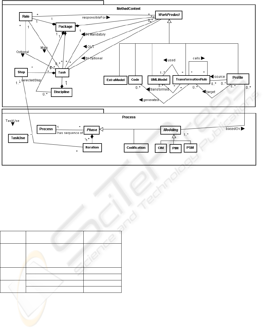
Figure 2: Specialized metamodel from some SPEM 2 concepts.
transformations should be applied. It is important to
define the sequence of activities for example, when
developer intervention in the diagrams to enable
transformation execution is necessary.
Table 1: Stereotypes of SPEM 2 associated to UML
diagrams (adapted from (OMG 2008)).
Diagram SPEM Stereotype UML
Element
Class
Package, Role,
WorkProduct, Task,
Step, Discipline, Phase,
Iteration, TaskUse
Class
Use Case
Role Actor
Task, WorkProduct Use Case
Activity
Task Action
WorkProduct Object
3.2 An Environment for Model-Driven
Process Modelling
An environment called Transforms has been
developed to support the modelling and enactment
of the proposed approach for MDA process
specification. This environment is divided into two
main modules: the MDA Process Edition and the
MDA Developer Edition as illustrated in Figure 3.
As we are focusing initially on the MDA process
modelling, we shall only present the Process Edition
module.
The Process Edition module is an environment
which provides authoring and customization of
MDA processes. As shown in Figure 3, the Process
Edition module encompasses four components:
process editor, profile editor, rule editor, and process
repository. The process editor is divided into three
diagram editors based on the UML: a class diagram
editor; a use case diagram editor; and an activity
diagram editor. This set of editors allows engineers
to model their processes according to the proposed
approach presented in Section 3. It is also possible to
specify a process using a breakdown structure and
automatic generated diagrams to represent it
visually. Examples from a case study are given in
the following section.
Both Profile and Rule editors are third party
software components attached to our solution in
such a way that users can create their own UML
profiles and/or write their own transformation rules
without going to another tool. The Process
Repository stores the information related to the
modelled process. After process definition the MDA
Developers Edition should be used.
ICEIS 2009 - International Conference on Enterprise Information Systems
30
Briefly, the MDA Developer Edition aims to
enact a process stored in the repository. A software
team should assume the process roles specified and
perform the Tasks defined in each discipline across
the process phases. Models should be produced and
generated until the achievement of code generation.
Process
Repository
Process Editor
MDA Process Edition MDA Developer Edition
Rule Editor Profile Editor
Code
PSM
PIM
CIM
Figure 3: Transforms solution.
4 A CASE STUDY: SPECIFYING
AN MDA PROCESS
In order to evaluate our approach, we specified the
MDA process proposed in (Maciel 2006a). In this
process, specific middleware services are defined
and implemented in EJB and CorbaCCM platforms.
4.1 Overview of the MDA Process for
Middleware Specific Services
Specific middleware services consist of a layer
above the common middleware services that
embody knowledge of a specific domain within the
middleware. Domain-specific middleware services
are not standardized. Their implementations are
usually tightly coupled to the middleware platform.
This implementation modelling requires
considerable effort that certainly would not be
rewarded if the service use were restricted to a
specific middleware platform (Schantz 2001). The
MDA process goals encompass the specification and
implementation of portable specific middleware
services. This process was applied to the
development of the InterDoc (Reference
Architecture for Interoperable Services in
Collaborative Writing Document Environments)
(Maciel 2005; Maciel 2006a).
The proposed MDA process includes the
following elements: (1) Three categories of
modelling phases according to the MDA
specification (CIM, PIM and PSM) (2) metamodels
with UML profiles (3) indication of a set of
diagrams for each modelling phase (4) a sequence of
steps to guide the modelling tasks and (5) mapping
rules among the UML models.
4.2 The MDA Process Specification
The MDA process introduced in the previous
subsection was originally described without any
standard language. Tables, illustrations and textual
documents were used to represent the process
specification. Tools were developed to support the
automation of model transformations related to the
process (Silva 2006; Pasini 2008). However, the
difficulty in understanding, reusing and evolving the
process structure and behaviour across development
teams became evident.
In order to adopt the approach presented in
Section 3.1, we mapped the process characteristics
to the concepts and associations of our metamodel
(Figure 2). Six disciplines were defined to group
related tasks: Enterprise View; Information View;
Computational View; Engineering View; Technology
View; and Services Implementation.
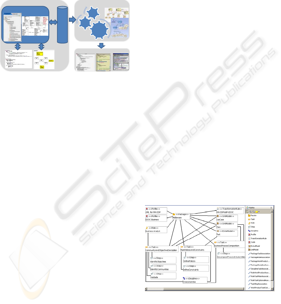
As described in section 3.1 the class diagram is
the first to be specified. It defines the overall
structure of the MDA process. Two class diagrams
were designed: one representing the method content
and the other representing the process structure.
Figure 4 illustrates the class diagram editor of the
Transforms tool. Due to the lack of space we present
only a piece of the method content modelling (in the
left side). The right palette organizes the necessary
buttons to model the structural and static view of the
method content. The editor only allows modelling
according to the metamodel defined in Figure 2.
Figure 4: CIM phase static structure.
The process life cycle is divided into three
modelling phases (CIM. PIM, PSM) and
codification. Each phase may comprise several
iterations allowing incremental process
AN APPROACH TO MODEL-DRIVEN DEVELOPMENT PROCESS SPECIFICATION
31

development. TaskUses are selected, according to
the steps previously defined in the method content,
to be performed during the iterations. At least one
activity diagram should be modeled for each phase
in order to compose the behaviour in terms of task
using and work products usages.
5 CONCLUSIONS AND FUTURE
WORKS
This paper has presented an approach for process
specification and enactment based on the concepts of
the SPEM 2 and MDA standards. We have
specialized some of the SPEM 2 metamodel
elements to provide a specific language to define
model-driven processes. As the SPEM metamodel
has a UML profile, our metamodel can be used
through any UML modelling tool. Moreover, we
have developed an environment with diagram
editors specific for the modelling which conforms to
our metamodel.
In addition to process modelling, our ongoing
work encompasses the tool-support of the process
enactment which includes the execution of model
transformations and code generation. In future work
our intention is twofold: to provide traceability
mechanisms across the process artefacts; and to
support other model transformation languages and
technologies. We are also planning a larger case
study to strengthen the evaluation of the proposed
environment in an organization which uses MDA.
ACKNOWLEDGEMENTS
This work is partially funded by Fapesb, project
number 8694/2006, and grant number 0002/2007.
REFERENCES
Humprey, W., Kelner,M. (1989) Software Modeling:
Principles of Entity Process Models. SEI - Carnegie
Mellon University. Pittsburgh, Pennsylvania,
(CMU/SEI-89-TR-2).
Jaccheri, M. L., Baldi M., Divitini M. (1999). Evaluating
the requirements of software process modeling
languages and systems, Process Support for
Distributed Team-based Software Development. In:
PDTSD99, Orlando, Florida, pages 570-578, August.
Koch, N. (2006). Transformation techniques in the model-
driven development process of UWE. In: Workshop
Proc. of the 6th intl Conference on Web Engineering
(Palo Alto, California). ICWE '06, vol. 155. ACM,
New York, 3.
Maciel, R., Ferraz, C., Rosa, N. (2005). InterDoc:
Reference Architecture for Interoperable Services in
Collaborative Writing Environments. In: 9
th
Intl.
Conference on CSCW in Design, May, England.
Maciel, R. S. P., Silva, B. C. e Mascarenhas, L. A.
(2006a). An Edoc-based Approach for Specific
Middleware Services Development, In: 4
th
Workshop
on MBD of Computer Based Systems, Postdam,
Germany. Proc. IEEE Press, p:135–143.
Maciel, R., Rosa, N., Ferraz, C. Silva, B. (2006b). Um
Processo MDA para o Desenvolvimento de
Componentes e Serviços Específicos de Middleware,
In: VI Workshop de Desenvolvimento Baseado em
Componentes, Recife, Brazil.
Pasini, K., Peixoto, R., Maciel, R., Duran, A. (2008). Uma
solução para apoiar um processo de desenvolvimento
dirigido a modelos usando openArchitectureWare. In:
IX Free Software Workshop / 9th Intl. Forum of Free
Software, Porto Alegre. p. 121-126.
Mellor, S. et al. (2004) MDA Distilled. EUA, Addisson-
Wesley.
OMG (2003). MDA Guide. Version 1.0.1 (omg/2003-06-
01).
OMG (2008). Software Process Engineering Metamodel
Specification, Version 2.0, (formal/08-04-01).
OpenUP Component – MDD (2008). Available at:
http://www.eclipse.org/epf/openup_component/mdd.p
hp.
Silva, B., Maciel, R., Mascarenhas, L. (2006) Transforms:
Uma Ferramenta MDA/EDOC para Desenvolvimento
de Serviços Específicos de Middleware. In: Brazilian
Symposium on Software Engineering – Tools session.
Florianópolis. Proc., p. 19-24.
Schantz, R., Schmidt, D. (2001). Middleware for
Distributed Systems: Evolving the Common Structure
for Network-centric Applications. Encyclopedia of
Software Engineering, Wiley & Sons.
Schmidt, D. (2006). Model-Driven Engineering. In:
Computer Magazine, p. 25-31. IEEE Computer
Society Press.
Wang, H., Zhang, D. (2003). MDA-based Development of
E-Learning System. In: 27
th
International Computer
Software and Applications Conference, Texas. Proc.
California: IEEE Press, p. 684.pi.
ICEIS 2009 - International Conference on Enterprise Information Systems
32
