
An Innovative Model Driven Formalization
of the Class Diagrams
Janis Osis and Uldis Donins
Department of Applied Computer Science, Institute of Applied Computer Systems
Riga Technical University, Meza iela 1/3, Riga, LV 1048, Latvia
Abstract. In this paper a system static structure modeling formalization and
formalization of static models based on topological functioning model (TFM) is
proposed. TFM uses mathematical foundations that holistically represent com-
plete functionality of the problem and application domains. With the TFM we
can do formal analysis of a business system and in a formal manner model the
static structure of the system. After construction of the TFM of a system func-
tioning a domain object model is defined by performing TFM transformation.
Making further transformations of TFM it is possible to introduce more formal-
ism in the unified modeling language (UML) diagrams and in their construc-
tion. In this paper we have introduced topology into the UML class diagrams.
1 Introduction
The Unified Modeling Language (UML) is a graphical language for visualizing,
specifying, constructing, and documenting the artifacts of a software-intensive
system. The UML offers a standard way to write a system's blueprints, including
conceptual things such as business processes and system functions as well as concrete
things such as programming language statements, database schemas, and reusable
software components. [8] and [3]
Since the publication of first UML specification researchers have been working
and proposing approaches for the UML formalization. Researches on UML
formalization are performed because the meaning of the language, which is mainly
described in English, is too informal and unstructured to provide a foundation for
developing formal analysis and development techniques, and because of the scope of
the model, which is both complex and large [2]. Despite the fact that the latest UML
specification [14] which is published by Object Management Group [4] is based on
the metamodeling approach, the UML metamodel gives information about abstract
syntax of UML but does not deal with semantics which is expressed in natural
language.
After the publication of the first UML specification precise UML (pUML) group
[13] was found with main goal to bring together international researchers and
practitioners who share the aim of developing the UML as a precise modeling
language. The aim of pUML group is to work firmly in the context of the existing
Osis J. and Donins U. (2009).
An Innovative Model Driven Formalization of the Class Diagrams.
In Proceedings of the 4th International Conference on Evaluation of Novel Approaches to Software Engineering - Evaluation of Novel Approaches to
Software Engineering, pages 134-145
DOI: 10.5220/0001951901340145
Copyright
c
SciTePress

UML semantics. As a formalization instrument they use several formal notations, for
example, Object Constraint Language [12] or the formal language Z [10].
There are also other researches on formalization of UML and class diagrams, for
example, [11] in which mathematical expressions are used to describe semantics of
the class diagrams.
All described researches are provided to formalize only the UML syntax but these
approaches does not:
• provide a formal way how to develop system description models in formal
manner,
• improve system description possibilities (for example, does not define new
associations or relations between classes), and
• use topology as a formalization tool of functioning.
The main idea of the given work is to introduce more formalism into the UML
class diagrams and propose a formal approach for developing class diagrams. For this
purpose formalism of a Topological Functioning Model (TFM) is used [6]. The TFM
holistically represents a complete functionality of the system from the computation-
independent viewpoint. It considers problem domain information separate from the
application domain information captured in requirements. The TFM is an expressive
and powerful instrument for a clear presentation and formal analysis of system
functioning and the environment the system works within. We consider that problem
domain modeling and understanding should be the primary stage in the software
development, especially in the case of embedded and complex business systems,
where failure can lead to huge losses. This means that class diagrams must be applied
as part of a technique, whose first activity is the construction of a well-defined
problem domain model.
This paper is organized as follows. Section 2 describes the suggested solution of
formalizing class diagrams by using topology which is defined with the help of TFM.
Section 3 discusses the use of TFM for problem domain modeling and creation of
topological class diagrams. TFM makes it possible to use a formal model as a
computation independent one without introducing complex mathematics. Besides
that, it allows validation of functional requirements at the beginning of the analysis.
By using TFM in the modeling process it is possible to introduce topology in the class
diagrams. As a result we have constructed a new type of class diagrams – topological
class diagrams. Description of the problem domain modeling is illustrated with an
example which clearly shows the process of developing topological class diagrams.
Section 4 gives conclusions of our work and discuss future work.
2 Formalization of the Class Diagram
Class diagrams reflect the static structure of the system, and with the help of class
diagrams it is possible to model objects and their methods involved in the system.
Regardless of the opportunities provided by the class diagrams, it is not possible to
reflect the cause and effect relation within a system or to indicate which certain ac-
tivity accomplishment of an object triggers another object’s certain activity accom-
135

plishment. By using the idea published in [5] about topological UML diagrams (in-
cluding topological class diagrams) we have developed method for construction of
topological class diagrams and developed the topological class diagram.
Before topological class construction it is needed to construct the TFM of the sys-
tem functioning. After construction of TFM it is possible to transform topology de-
fined in TFM into class diagrams and in such a way introduce more formalism into
class diagrams. It is possible to transform topology from TFM into class diagrams
because TFM has strong mathematical basis. In this way the formalism of class dia-
grams means that between classes are precisely defined relations which are identified
from the problem domain with help of TFM. In traditional software development
scenario relations (mostly associations and generalizations) between classes are de-
fined by the modeler’s discretion.
TFM has strong mathematical basis and is represented in a form of a topological
space (X, Θ), where X is a finite set of functional features of the system under con-
sideration, and Θ is the topology that satisfies axioms of topological structures and is
represented in a form of a directed graph. The necessary condition for constructing
the topological space is a meaningful and exhaustive verbal, graphical, or mathemati-
cal system description. The adequacy of a model describing the functioning of a con-
crete system can be achieved by analyzing mathematical properties of such abstract
object [6].
A TFM has topological characteristics: connectedness, closure, neighborhood, and
continuous mapping. Despite that any graph is included into combinatorial topology,
not every graph is a topological functioning model. A directed graph becomes the
TFM only when substantiation of functioning is added to the above mathematical
substantiation. The latter is represented by functional characteristics: cause-effect
relations, cycle structure, and inputs and outputs. It is acknowledged that every busi-
ness and technical system is a subsystem of the environment. Besides that a common
thing for all system (technical, business, or biological) functioning should be the main
feedback, visualization of which is an oriented cycle. Therefore, it is stated that at
least one directed closed loop must be present in every topological model of system
functioning. It shows the “main” functionality that has a vital importance in the sys-
tem’s life. Usually it is even an expanded hierarchy of cycles. Therefore, a proper
cycle analysis is necessary in the TFM construction, because it enables careful analy-
sis of system’s operation and communication with the environment [6].
There are two stages at the beginning of the problem analysis: the first one is anal-
ysis of the business (or enterprise system) context (the problem domain) and the
second one is analysis of the application context (the application domain). These
levels should be analyzed separately. The first idea is that the application context
constrains the business context, not vice versa. The second idea is that functionality
determines the structure of the planned system (Fig. 1). Having knowledge about the
complex system that operates in the real world, a TFM of this system can be com-
posed.
136
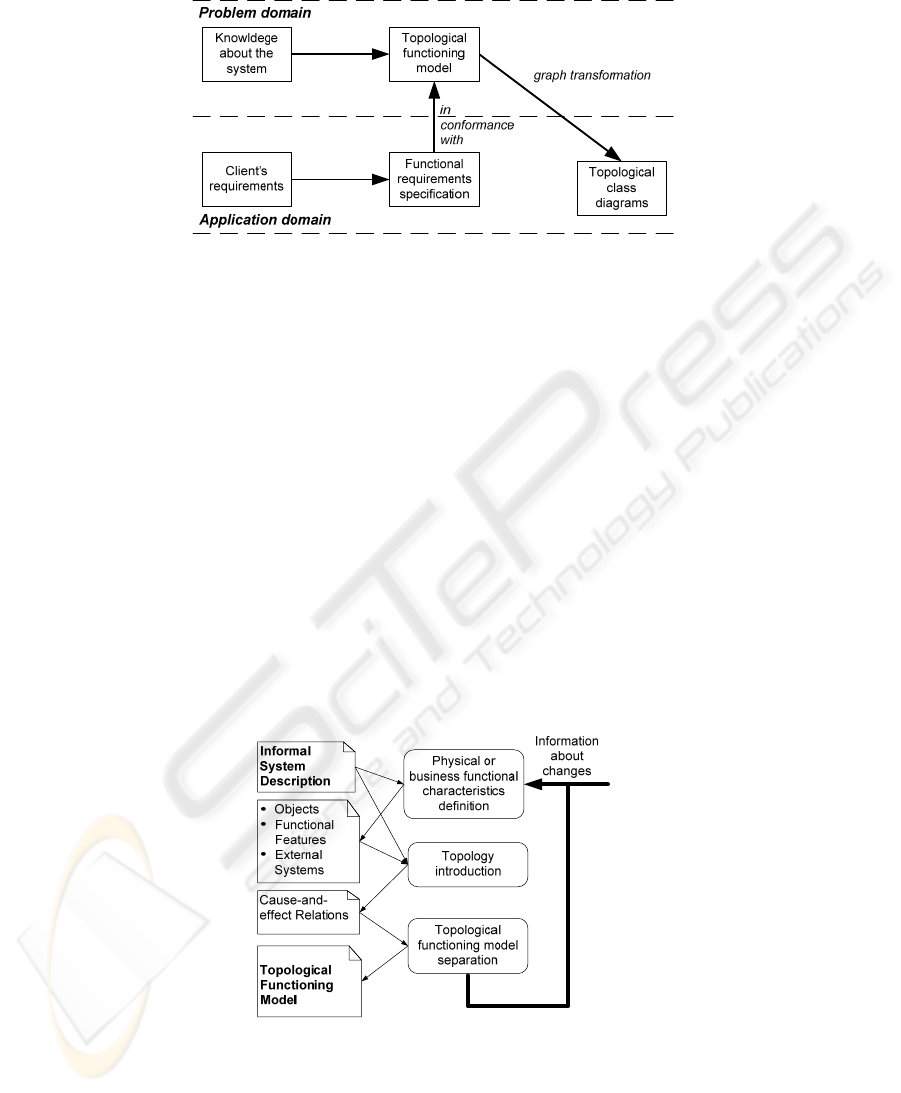
Fig. 1. Creation of the software design using the TFM.
In [7] it is suggested that problem domain concepts are selected and described in
an UML Class Diagram. In our work we select and describe problem domain con-
cepts by means of topological class diagrams. All these steps are illustrated by the
example given in next section.
3 Case Study of the Construction of the Topological Class
Diagram
For a better understanding of the construction of the TFM and topological class dia-
gram let us consider small fragment of an informal description from the project de-
fined in [7], in which a library application is developed.
3.1 The Construction of the Topological Functioning Model
Construction of the TFM consists of three steps [5] (see Fig. 2).
Fig. 2. The construction of the TFM [7].
137

The steps for the TFM construction are:
Step 1: Definition of physical or business functional characteristics, which con-
sists of the following activities:
1) definition of objects and their properties from the problem domain descrip-
tion;
2) identification of external systems and partially-dependent systems; and
3) definition of functional features using verb analysis in the problem domain
description, i.e., by finding meaningful verbs.
Within the [1] it is suggested that each functional feature is a tuple (1),
<A, R, O, PrCond, PostCond, E, Cl, Op> (1)
where:
• A is an object action,
• R is a result of this action,
• O is an object (objects) that receives the result or that is used in this action
(for example, a role, a time period, a catalogue, etc.),
• PrCond is a set PrCond = {c1, …, ci}, where ci is a precondition or an atom-
ic business rule (it is an optional parameter),
• PostCond is a set PostCond = {p1, …, pi}, where pi is a postcondition or an
atomic business rule (it is an optional parameter),
• E is an entity responsible for performing actions,
• Cl is a class which will represent in system static model the object which
will contain operation for functionality defined by this functional feature
(this parameter can be fulfilled when the class diagram is synthesized), and
• Op is an operation which will contain functionality defined by functional
feature (this parameter can be fulfilled when the class diagram is synthe-
sized).
We have added parameters Cl and Op to tuple defined in [1] to contain in the tuple
all the information about functional feature. If there is a need to store additional in-
formation about functional features then it is possible to add more parameters to this
tuple.
Each precondition and atomic business rule must be either defined as a functional
feature or assigned to an already defined functional feature.
For the library project example we have defined the following 29 functional fea-
tures (in the form of tuple containing the following parameters: identificator, object
action (A), precondition (PrCond), object (O), mark if functional feature is external or
internal), where Rec denotes Receptionist, R – Reader, L – Librarian, In – Inner, and
Ex - External:
<1, A visitor arriving in the library, Ø, Visitor, Ex>, <2, Checking of personal data
with the library readers’ register, Ø, Rec, In>, <3, Reader’s registration in the library
readers’ register, if the person is not registered in the readers’ register yet, Rec, In>,
<4, Reader’s card preparation, if the reader does not have the reader’s card yet (or) if
the reader has lost his/her reader’s card, Rec, In>, <5, Reader’s card issue to the read-
er, Ø, Rec, In>, <6, The reader status authorization, if the reader is registered (and) if
the reader has the reader’s card, R, In>, <7, Searching for a book in the book cata-
138

logue, if the reader has the reader’s card, R, In>, <8, Completion of the book request
form, if the reader has found the book he or she needs, R, In>, <9, Submission of the
book request form, Ø, R, In>, <10, Count of books borrowed by the reader, Ø, L, In>,
<11, Checking of the book availability in the book repository, if the number of books
borrowed by the reader does not exceed the maximum allowed, L, In>, <12, Taking
the book from the book repository, if the book is available in the book repository, L,
In>, <13, Handing out the book to the reader, Ø, L, In>, <14, Borrowing the book, Ø,
R, In>, <15, Book return, Ø, R, Ex>, <16, Checking of the book condition, Ø, L, In>,
<17, Fine calculation, if the book is damaged, L, In>, <18, Handing out the fine tick-
et, Ø, L, Ex>, <19, Fine payment, Ø, R, Ex>, <20, Book return/placement into book
repository, Ø, L, In>, <21, Book withdrawal, if the book is extremely damaged (can-
not be used anymore), L, Ex>, <22, Book removal from the catalogue, in case of the
last copy of the book, L, In>, <23, New book purchase, Ø, Library, Ex>, <24, Books
data entry into catalogue, if the library does not have a copy of this book, Rec, In>,
<25, Book identification number assignment, Ø, Rec, In>, <26, Book utilization, If
the book is extremely damaged, Utilizer, Ex>, <27, Book repository maintenance, Ø,
L, In>, <28 Completion of the book utilization request form, Ø, L, In>, and <29, The
fine deletion, if the reader has paid the fine, L, In>.
Step 2: Introduction of topology
Θ
, which means establishing cause and effect re-
lations between functional features. Cause-and-effect relations are represented as arcs
of a directed graph that are oriented from a cause vertex to an effect vertex.
Fig 3. Topological space of the library functioning.
The identified cause-and-effect relations between the functional features are illu-
strated by the means of the topological space (see Fig. 3). In the Fig. 3 is clearly visi-
ble that cause-and-effect relations form functioning cycles. All cycles and sub-cycles
should be carefully analyzed in order to completely identify existing functionality of
the system. The main cycle (cycles) of system functioning (i.e., functionality that is
vital for the system’s life) must be found and analyzed before starting further analy-
sis. In the case of studying a complex system, a TFM can be divided into a series of
subsystems according to the identified cycles.
Step 3: Separation of the topological functioning model, which is performed by
applying the closure operation over a set of system’s inner functional features [6]: A
topological space is a system represented by Equation (2),
139

Z = N
∪
M
(2)
where N is a set of inner system functional features and M is a set of functional
features of other systems that interact with the system or of the system itself, which
affect the external ones.
A TFM (X∈Θ) is separated from the topological space of a problem domain by the
closure operation over the set N as it is shown by Equation (3),
[]
U
n
XNX
1=
==
η
η
(3)
where Xη is an adherence point of the set N and capacity of X is the number n of
adherence points of N.
An adherence point of the set N is a point, whose each neighborhood includes at
least one point from the set N. The neighborhood of a vertex x in a directed graph is
the set of all vertices adjacent to x and the vertex x itself. It is assumed here that all
vertices adjacent to x lie at the distance d=1 from x on ends of output arcs from x.
The example below illustrates how we perform the closuring operation (3) over the
set N in order to get all of the system’s functionality – the set X. The set of the sys-
tem’s inner functional features N = {2, 3, 4, 5, 6, 7, 8, 9, 10, 11, 12, 13, 14, 16, 17,
20, 21, 22, 24, 25, 27, 28, 29}. The set of external functional features and system
functional features that affect the external environment M = {1, 15, 18, 19, 21, 23,
26}. The neighbourhood of each element of the set N is as follows: X
2
= {2, 3, 4, 6},
X
3
= {3, 4}, X
4
= {4, 5}, X
5
= {5, 6}, X
6
= {6, 15}, X
7
= {7, 8}, X
8
= {8, 9}, X
9
= {9,
10}, X
10
= {10, 11}, X
11
= {11, 12, 27}, X
12
= {12, 13, 27}, X
13
= {13, 14}, X
14
=
{14, 6}, X
16
= {16, 17, 20, 21}, X
17
= {17, 18}, X
20
= {20, 7, 27}, X
22
= {22, 7}, X
24
= {24, 7, 25}, X
25
= {25, 20}, X
27
= {27}, X
28
= {28}, and X
29
= {29}.
The obtained set X (the TFM) = {2, 3, 4, 5, 6, 7, 8, 9, 10, 11, 12, 13, 14, 15, 16,
17, 18, 20, 21, 22, 24, 25, 27, 28, 29}.
Obtained TFM of library functioning after performing closuring operation over the
set of system inner functional features (the set N) can be seen in Fig. 4.
Fig. 4. Topological functioning model of the library functioning.
The example represents the main functional cycle defined by the expert, which in-
cludes the following functional features “6-15-16-20-7-8-9-10-11-12-13-14-6” and is
denoted by bold lines in Fig. 4. These functional features describe checking out and
140

taking back a book. A cycle that includes the functional features “6-7-8-9-10-11-12-
13-14-6” illustrates an example of the first-order sub-cycle. And these functional
features describe checking out a book.
3.2 Construction of the Topological Class Diagram
In the [7] is offered the conceptual development of class diagrams as the final step of
the TFM usage. In this conceptual class diagram relevant information – directions of
associations between the classes – is lost. This important information is lost because
within approach given in [7] the relations between classes are defined with one of the
relations defined in UML – the associations. It is not possible to transform topologi-
cal (cause and effect) relations between TFM’s functional features into associations
between classes. It is impossible because:
1) the direction of topological relation is not always the same as direction of as-
sociation,
2) association also can be bidirected (topological relationship can not be bidi-
rected), and
3) topological relationship only can be binary relation (association can relate
more than two classes, for example, ternary association which relates three
classes).
Because of this constraint in [7] it is recommended to define those association di-
rections in further software development, for example, to develop a more detailed
software design. But at this point a step back should be taken to review the TFM and
its transformation on the conceptual class diagram. To avoid such regression and to
save the obtained topology between the classes, by using the idea published in [5]
about topological UML (TopUML) diagrams (including topological UML class dia-
grams), it is possible to develop a topological class diagram where the established
TFM topology between classes is retained. The retained topology (cause and effect
relations between classes) in class diagrams brings more formalism in these class
diagrams. Formalism of class diagrams is improved because between classes now are
precisely defined relations. In traditional software development relations (mostly
associations and generalizations) between classes are defined by the modeler’s discre-
tion (the approach given in the [7] helps to identify associations between classes but
the identification of direction for these associations again is defined by the modeler’s
discretion).
Topological relations between classes throughout this article are marked with di-
rected arcs (this means that within this article notation used for topological relations
between classes is similar to notation of associations in UML). The example of topo-
logical relations can be viewed in Fig. 5.
In order to obtain a topological class diagram, first of all a graph of problem do-
main objects must be developed and afterwards transformed into a class diagram. In
order to obtain a problem domain object graph, it is necessary to detail each function-
al feature of the TFM to a level where it uses only one type of objects.
141
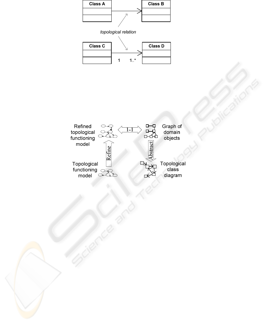
Fig. 5. Topological relations between classes.
After construction of domain object graph this more accurate model must be trans-
formed one-to-one to a problem domain object graph and then the vertices with the
same type of objects and methods must be merged, while keeping all relations with
other graph vertices. As a result, object graph with direct links is defined. Schematic
representation of class diagram development is given in Fig. 6.
Fig. 6. The process of the development of the topological class diagram.
By using the ideas published in [7] it is possible to obtain from TFM a conceptual
class diagram without orientated relations between classes and the classes without
operations. Modifying this approach it is possible to develop not only topological
class diagrams, where the direction of relations is retained, but also to obtain the
possible class operation definitions. In order to define conceptual operations, it is
necessary to change not only every functional feature to one kind of object, but also
by doing this transformation, to add a operation to the obtained (using a point nota-
tion), the description of which shortly describes the defined activity of the functional
feature, for example, the functional feature "The reader’s card issue to the reader" is
transformed to the object "ReaderCard" and the method "GiveOutToReader()" (when
point notation is used the obtained result looks like this: "Reader-
Card.GiveOutToReader()").
At this moment it is possible to add additional information to the tuple (fulfil pa-
rameters Cl and Op) which is describing functional feature. After adding two parame-
ters describing class and operation the tuple looks like this: <5, Reader’s card issue
to the reader, Ø, Rec, In, ReaderCard, GiveOutToReader>.
Our example skips the step of the topological functioning model refinement, be-
cause each functional feature deals only with one type of objects and operations. Fig.
142
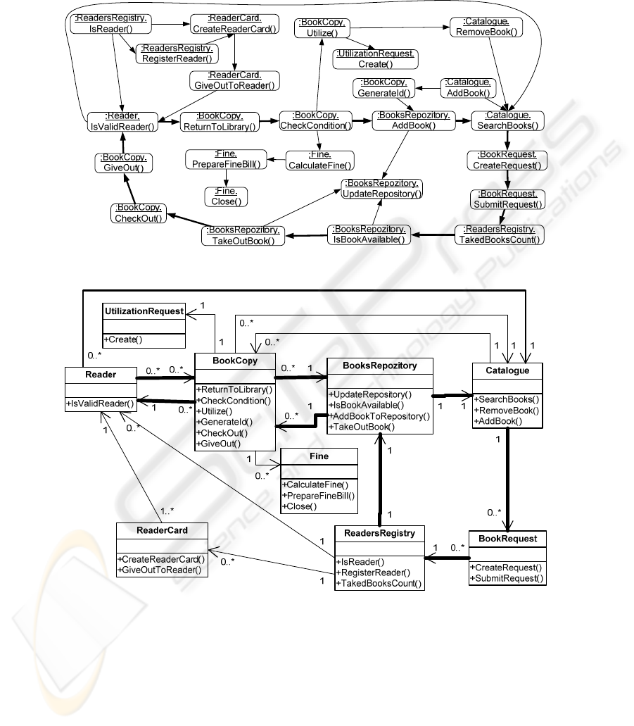
7 shows the transformation of the topological functioning model to the graph of do-
main objects with conceptual operations.
Fig. 7. The graph of domain objects with operations.
Fig. 8. Topological class diagram.
Fig. 8 presents topological class diagram of the library example after domain ob-
ject graph is abstracted, i.e., after merging all graph vertices with the same object
types.
With the boldest lines in developed topological class diagram is maintained main
functional cycle which is defined by the expert within the constructed TFM. This
143

reflects the idea proposed in [6] and [5] that the holistic domain representation by the
means of the TFM enables identification of all necessary domain concepts and, even,
enables to define their necessity for a successful implementation of the system.
The topological (cause and effect) relationship between classes, which are de-
scribed with one way directed arc, cannot be compared with none of the UML rela-
tionships between the classes given in UML language specification [14]. The UML
language specification gives the following relationships between the classes:
• association (including aggregation and composition),
• generalization,
• dependence,
• usage,
• abstraction,
• realization, and
• substitution.
All previously mentioned relationships between classes define only the way in
which the classes interact and use each other [9], but the adopted topology in class
diagrams allows to keep the cause and effect relationships between objects. The saved
topology between classes in class diagram enables more efficient development of the
software system class diagram.
By keeping topological relationships between the classes it is recommended to use
one-way association, because two mutually opposed associations between two classes
can represent various multiplications. If topological class diagram is used to make the
non-oriented class diagram, then relations between two classes can be joined into one,
and as a multiplicity save the biggest multiplicity of all topological associations be-
tween those two classes.
4 Conclusions and Future Work
The application of the TFM has the following advantages:
• With the help of TFM it is possible to introduce more formalism in the UML
diagrams and in their construction. In our work we have shown that it is
possible to maintain in the class diagrams the topology which is developed
using TFM.
• Using TFM for problem domain modeling and application domain definition
it is possible to provide traceability between software requirements, func-
tional features and even developed architecture elements.
• By performing TFM transformations it is possible to develop problem do-
main objects’ graphs and topological class diagrams.
• Topological class diagram can also be used as architecture for the new sys-
tem. With the help of TFM and topological class diagrams it is possible to
develop software system’s business layer which corresponds to the defined
requirements.
144

To continue working on topological UML diagrams, it is necessary to supplement
the description of topological class diagrams, to create the meta-model of the topolog-
ical class diagram as well as to study the possibilities of topology implementation into
other UML diagrams (for example, activity diagrams) and to assess its influence on
the software system development.
References
1. Asnina, E.: The Formal Approach to Problem Domain Modelling Within Model Driven
Architecture. In: Proceedings of the 9
th
International Conference “Information Systems Im-
plementation and Modelling” (ISIM’06), pp. 97-104, Přerov, Czech Republic. Jan Štefan
MARQ. (2006)
2. Evans, A., & Kent, S. (1999). Core Meta-Modelling Semantics of UML: The pUML Ap-
proach. “UML”’99 – The Unified Modeling Language. Lecture Notes in Computer
Science, Vol. 1723. Springer-Verlag Berlin Heidelberg New York (1999) 140-155
3. Fowler, M.: UML Distilled: A Brief Guide to the Standard Object Modeling Language, 3
rd
ed. Addison-Wesley (2003)
4. Object management group (OMG) http://www.omg.org (2008)
5. Osis J.: Extension of Software Development Process for Mechatronic and Embedded Sys-
tems, Proceeding of the 32nd International Conference on Computer and Industrial Engi-
neering, University of Limerick, Limerick, Ireland, pp. 305-310 (2003)
6. Osis, J.: Formal Computation Independent Model within the MDA Life Cycle, Internation-
al Transactions on Systems Science and Applications, Vol. 1, No. 2, pp. 159 – 166 (2006)
7. Osis, J., Asnina, E.: Enterprise Modeling for Information System Development within
MDA. In: Proceedings of the 41
st
Annual Hawaii International Conference on System
Sciences (HICSS 2008), USA, p. 490 (2008)
8. Rumbaugh, J., Jacobson, I., & Booch, G.: The Unified Modeling Language Reference
Manual, 2
nd
ed. Addison-Wesley (2004)
9. Rumbaugh, J., Jacobson, I., & Booch, G.: The Unified Modeling Language User Guide, 2
nd
ed. Addison-Wesley (2005)
10. Spivey, J. M.: The Z Notation: A Reference Manual, 2
nd
ed. Prentice Hall (1992)
11. Szlenk, M.: UML Static Models in Formal Approach. Balancing Agility and Formalism in
Software Engineering. Lecture Notes in Computer Science, Vol. 5082. Springer-Verlag
Berlin Heidelberg New York (2008) 129-142
12. Warmer, J., & Kleppe, A.: The Object Constraint Language: Getting Your Models Ready
for MDA, 2
nd
ed. Addison-Wesley (2003)
13. The Precise UML group (pUML) http://www.cs.york.ac.uk/puml/ (2004)
14. OMG: Unified Modeling Language Superstructure Specification, version 2.1.2 (2007)
145
