
Database-Driven Concept Management:
Lessons Learned from using EJB Technologies
Daniela Pohl and Andreas Bollin
Software Engineering and Soft Computing, Klagenfurt University
Universit¨atsstrasse 65-67, Klagenfurt, Austria
Abstract. During software maintenance activities one needs tools that assist in
concept location and that provide fast access to already identified concepts. Thus,
this paper presents an approach that is able to cope with this situation by storing
concepts in a database. We demonstrate its applicability on formal Z specifica-
tions, where the huge number of concepts to be found emphasizes the use of an
efficient database system. The paper closes with lessons learned, as the standard
use of EJB-technologies redounds to more time-complexity than expected.
1 Introduction
As developers we are surrounded by complexity. Partly, this is because our applications
get more sophisticated. Partly, this is because also our objectives get more and more
complex. With it the related design documents explode in size and imply complica-
tions. This situation was already reflected by C.A.R. Hoare in the 1980s, who stated
that [..] there are two ways of constructing a software design: One way is to make it
so simple that there are obviously no deficiencies and the other way is to make it so
complicated that there are no obvious deficiencies [1]. Small artifacts are rather excep-
tions, and locating deficiencies is a major business for a software personnel. The bad
news is that fixing deficiencies is impeded by the very mentioned problems of size and
complexity.
As scientists we are faced with the challenge to overcome at least parts of these
hurdles. First, we have to sustain the understanding of relevant parts of a system and its
related maintenance activities. Secondly, we have to ensure that the relevant parts (to
be changed) can be located easily. These tasks are supported by software comprehen-
sion environments [2–5], reverse engineering frameworks [6–10], and concept location
tools [11–13]. They focus i.a. on either data-gathering, exploration and visualization
of the code, and assist in knowledge organization. But concept location is not only re-
stricted to programming languages. There are also techniques for formal specifications
[14] or rule-based systems [15]. There, the approaches make use of the identification
of relationships and the reconstruction of concepts by means of slicing, chunking, and
clustering.
Despite these existing tools, concept location is still a laborious task. Over sev-
eral periods of time often the same or similar concepts have to be reconstructed again
and again, which is, additionally, a resource and time-consuming process. Therefore,
Pohl D. and Bollin A. (2009).
Database-Driven Concept Management: Lessons Learned from using EJB Technologies.
In Proceedings of the 4th International Conference on Evaluation of Novel Approaches to Software Engineering - Evaluation of Novel Approaches to
Software Engineering, pages 227-238
DOI: 10.5220/0001954502270238
Copyright
c
SciTePress

this contribution suggests a framework that persistently stores conceptual elements and
their dependencies in an SQL database. In 2008, a prototype has been implemented in
the course of the master thesis of Pohl [16], and this contribution aims at sharing our
experiences with the system and its evaluation.
This paper is structured as follows: Sec. 2 introduces the notion of concepts and
their detection, first in general, and then in formal Z specifications. Sec. 3 presents the
architecture of the framework and the related database model. Sec. 4 is dedicated to the
use of Enterprise Java Beans (EJB). Sec. 5 describes the evaluation steps and lessons
learned. Finally, Sec. 6 concludes this contribution with a short summary.
2 Concepts and Concept Location
When trying to understand a system, concepts are generally seen as perceived regulari-
ties in events or objects, or records of events or objects, designated by a label [17]. One
is looking for related parts and trying to assign a name/meaning to them. Additionally,
by aggregation, new (abstract) concepts can be built. The concepts we are looking for
are exactly those parts with dependencies within and across artifacts.
Concept Location is rather intuitive. Experienced users manage to navigate quickly
around relevant parts but fail in explaining how they are excluding irrelevant parts.
When their experience does not suffice, they follow three different strategies which are
explained in more detail in [17]: (string) pattern matching, dynamic analysis, and static
analysis. The process of concept location is iterative. By starting with a domain-level
request, concept candidates are identified and evaluated with respect to their suitability
and then they are either rejected or form the basis for the next evaluation step.
In order to demonstrate generality, we decided to focus on artifacts that are at a
very high abstraction level and that are inherently complex: formal Z specifications
[18]. They seem to be most useful as they are semantically very compact and are of a
declarativenature. This implies that dependencies are definitely hard to identify, and the
assumption is that other artifacts (like program text) will not complicate the situation.
Concept identification within formal specifications depends on the notion of control
and data dependencies between their basic elements (also called primes). Their calcu-
lation is impeded by their declarative nature, but (with some limitations) they can be
reconstructed. Basically, this is done by regarding scope rules, looking at the primes’
identifiers, and, depending on their use, by assigning definition (D) declaration (T) and
use (U) tags to them. Primes that describe an after state (they contain at least one D-
tag) are said to be control dependent on primes that do not describe such an after state.
When taking a specific identifier within the primes into account, data dependencies can
be detected. For an in-depth discussion on dependencies and concepts see [19].
Based on the identified dependencies, the following partial specifications can be
defined: specification slices, chunks, and clusters. Slices and chunks are generated by
looking at a starting set of primes and by following control and/or data dependencies.
Clusters are calculates by taking reachability considerations into account. These speci-
fication abstractions are hereinafter treated as concepts that are to be identified via and
stored in the database. The following section introduces the architecture of the frame-
work and the related database schema.
228
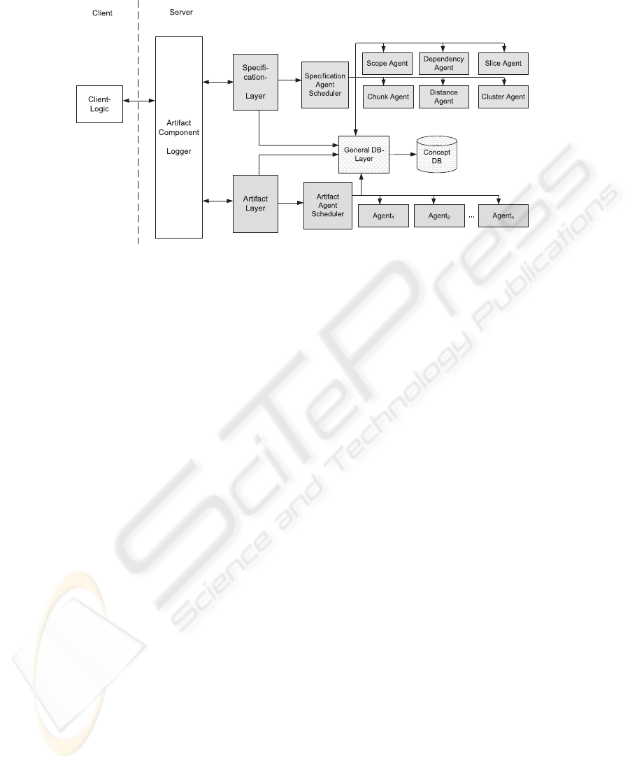
Fig.1. Architecture as implemented by the framework.
3 Architecture
The framework for identifying the different concepts in Z specifications is based on
the architecture as shown in Fig. 1. It is designed to easily cope with different types of
artifacts as the server is divided into three main parts:
1. Artifact Independent Layer: This layer represents the interface to the client and
the component-logger.
2. Artifact Depended Layer: Depending on the type of the artifact (in our example
Z specifications) this layer contains the control logic and the corresponding agents.
3. General Database Layer: This layer provides the necessary interface for manipu-
lating the database.
The framework implements a traditional client-server architecture pattern. The client is
responsible for visualizing the results and for triggering the concept extraction. On the
server side it is designed to handle different types of artifacts. The Artifact-Component
Logger is responsible for the registration of different Artifact-Layers. Depending on the
document to be stored (or accessed), the logger identifies the responsible layer. In our
case (for a Z-Specification) the Specification-Layer is contacted. The artifact layers are
responsible for implementing the necessary concept location functionality. Complex or
time-consuming tasks (e.g. the dependency calculation) can be delegated to Agents that
are synchronized by the Artifact Agent Scheduler.
Whenever a document is stored, different analysis tasks will have to be started to
extract concepts, and the findings will have to be stored in the database again. In our
prototypical implementation, every agent is responsible for one specific concept class.
E.g. the Dependency Agent extracts data and control dependencies.The Cluster Agent is
then used to calculate all possible clusters within one document. As clusters are created
by looking at strongly-connectedparts, this agent is scheduled not until the Dependency
229

Agent has finished its calculation. A more detailed description of the agents is given in
Sec. 3.2.
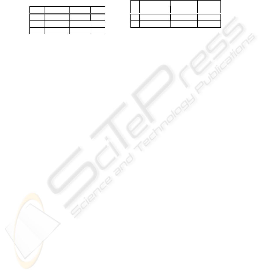
3.1 Database
The database schema (see Fig. 4 in the Appendix) can be divided into four parts: the
Management/Project Pane, the Representation Pane, the Concept Pane, and the View
Pane. Concept location can be treated as a multi-dimensional problem, and the dimen-
sions, explained in more detail in [16], are just mapped to the corresponding parts in
the schema. They are described hereinafter shortly:
During development and maintenance it is common to deal with different types
and versions of documents, and the Management/Project Pane covers this function-
ality. Therewith, it is possible to store different Artifacts of the software engineering
process. They are related to a specific Project and Phase (within they are generated).
An artifact consists of different SyntaxElements. As introduced above, in Z we call
those elements primes. They form basic concepts of the artifact and are stored in the
(Syntactic) Representation Pane of the database. The underlying structure of the doc-
ument (and respectively of the elements) can be any simple or complex graph and is
expressed by a circular n-to-m relationship. For future processing steps it is possible to
annotate those elements. One type of annotation is the use of identifiers (e.g. T, D, or
U) within primes (as mentioned earlier in Sec. 2).
Based on these annotations, concepts are extracted. They are handled within the
Model ConceptPane. As there are different typesof Concepts(e.g. dependencies,slices,
cluster, and chunks) and as concepts can form hierarchies, again an n-to-m recursive
relationship has been chosen to allow for greater flexibility. Additionally, for every con-
cept, it is possible to store ConceptMetaData information.
Finally, different Views onto artifacts might exist. Those views cluster concepts of
the same type together (e.g. all control dependencies of the document). Views are rep-
resented within the (Concept) View Representation Pane. The set of all views can be
seen as a semantic snapshot of the whole document.
As mentioned above, every class of concepts is identified by an associated agent
which is also responsible for storing the concepts in their corresponding views. The
strength of the approach is its flexibility based on the use of a relational database.
Agents just commit SQL queries to aggregateand store the necessary information. They
are described in the following section.
3.2 Agents
Most of the work is done by agents. They are running independently from the client
on the server side and interact with the database. It is possible to extend the framework
by additional agents. The agents currently implemented in the prototype are: the Scope
Agent, the Dependency Agent, the Distance and Cluster Agent, the Slice Agent, and the
Chunk Agent.
Data and control dependencies between primes can only be detected when the scope
(where the elements are involved) is clear. Thus, first the scope has to be extracted from
the syntactical structure of the artifact.
230

Π
sid
σ
AnnotationType.name=”D”
((σ
Concept.id=act
Concept ⊲⊳
(σ
ConceptType.name=”State”
ConceptType))
⊲⊳ SyntaxElement ⊲⊳
ElementMetaData ⊲⊳ AnnotationType)
(1)
Π
sid
(σ
Concept.id=act
Concept ⊲⊳
(σ
ConceptType.name=”State”
ConceptType))
[sid 6= sid]
Π
sid
(σ
AnnotationType.name6=”T”or
AnnotationType.name6=”CorAnnotationType.name6=”D”
SyntaxElement ⊲⊳ ElementMetaData
⊲⊳ AnnotationType)
(2)
In our system the Scope Agent is responsible for that. In fact, what we informally call
”scope” has three facets in Z: the State Scope which deals with schema and schema
inclusions within a specification document, the Connectivity Scope which merges all
primes of two or more schemata that are combined via schema operations, and the
Declaration Scope that merges all primes that are necessary to keep it syntactically
correct
1
.
When the scope is fixed, the Dependency Agent is started and identifies control and
data dependencies. Both, dependencies and scopes are stored as concepts within the
database. An example of the State Scope can be found in Fig. 2 (out of the Birthday-
Book specification of [18]). Due to schema inclusion, the primes of the ”BB” state space
are combined with the primes of the ”Add” operation schema.
The next two agents are the Distance and Cluster Agents. For clustering formal Z
specifications, distances between primes (across dependency paths) are taken. So the
first agent calculates the distances between the primes in the specification. The second
agent then calculates all potential clusters within one artifact.
Common abstractions with a clearly defined meaning are slices and chunks. The
next two agents, the Slice and Chunk Agent, are responsible for extracting them. They
look at every prime, take them as slicing/chunking criterion and, by following control
and/or data dependencies, they calculate these forms of abstraction.
3.3 Dependency Agent
The Dependency Agent is described hereinafter in more details as its functionality
demonstrates the ease of working with the database. Based on pre-identified scopes
(that are already stored as concepts in the database), it is possible to calculate depen-
dencies between syntactical elements.
To identify control dependencies within Z, some approximationscan be conducted [14]:
a syntactical element is control dependent upon another one, iff there is another element
that decides whether the prime is evaluated or not. By utilizing the use-annotations (U)
it is possible to identify these dependencies with ease. The calculation can be done by
small queries (demonstrating the elegance of the approach). The queries (1) and (2)
above calculate the start and the end positions of the control dependency arcs
2
.
1
The different types of scope are explained in more details in [16].
2
The act identifier holds the scope for which the current calculation is to be performed.
231

Fig.2. Scope and resulting data/control dependency.
The dependency agent takes all results of the first query and connects them with the
resulting elements of the second query. The same is done for data dependencies. Addi-
tionally, the identified pairs of dependencies are stored as concepts within the database.
For the Add-Operation the resulting dependencies are shown in Fig. 2.
As the framework is assumed to be extend, maintainability was an important re-
quirement during development. The choice dropped onto the EJB-Technology. The
evaluation of the prototype also reflects on EJB internals, so the following section dis-
cusses the most important issues. More information about EJB can be found in [20].
4 EJB and Implementation Details
EJB 3.0 (Enterprise Java Beans) is a server-side middleware architecture of Sun Mi-
crosystems. The reason for choosing this technology was the non-functional require-
ment maintenance we wanted to guarantee, and EJB facilitates this separation between
the application and the database logic. Additionally, it offers bean-objects to handle
data easily and to map the relational data format to the object oriented paradigm re-
spectively. This fact could be understood as an abstraction of the relational database
schema in an object oriented presentation.
The EJB technology is implemented via corresponding Java classes on the server
which run in an EJB-Container. For the implementation of various functionalities dif-
ferent types of beans are provided. Special beans are needed for the connection to the
database, the so-called Entity Beans. One object of an Entity Bean class holds one row
of the appropriate table. Thus beans are the results of the object-oriented mapping pro-
vided by this technology.
The concept management framework is realized via Java 1.6, EJB 3.0 and the Open-
Source database system MySql. For the server side implementation the application
server Glassfish
3
from Sun was used. The development environment was NetBeans
IDE 6.0.1. The ORM (Object-Rational-Mapping) is provided by the TopLink persis-
tence provider, developed by Oracle.
The framework implements the architecture as described in Sec. 3. The client is
a stand-alone remote client and thus not executed in an EJB-Container. The server
3
For further information about Glassfish see: https://glassfish.dev.java.net/, Last visit:
Feb. 2009.
232
is implemented via EJB. The interface to the client (Artifact Component Logger) is
represented by a stateless session bean. The different artifact dependent layers (as the
Specification Layer) are also implemented as stateless session beans. Thereby, it is pos-
sible to serve more than one client at a time. This layer is also responsible to start the
Agent Scheduler. The Agent Scheduler for Z specifications is a traditional Java class,
which consults the agents as needed. The Agents are also traditional Java classes. For
the persistency of the identified concept they get the entity manger from the current
session. The interface to the database is formed by entity beans which map the database
relations to the object oriented classes. Thus, these beans are contained as part in the
General DB-Layer.
5 Evaluation
The evaluation of the framework was carried out in two steps. First, the correctness
of the identified concepts were checked, and, secondly, the usefulness in respect to
performance explored. In fact, both steps also hearken back to results of an existing
framework called ViZ (for Visualization of formal Z specifications [19]). ViZ maps Z
specifications to a graph (primes become vertices, dependencies are stored as arcs) and
calculates dependencies based on reachability considerations.
5.1 Setting and Correctness
The first step was the validation of the concepts that have been identified by the agents
and stored in the database. The evaluation is based on wide-spread specifications of
raising sizes, known as Birthday Book [18], Petrol Station [14], and Elevator [21]. Ad-
ditionally, a student’s specification (called Cinema) was added to the set, too. Tab. 1
(left side) presents the complexities of the specifications by exemplifying the number
of pages (when pretty-printed), primes, control- (CD), and data dependencies (DD).
An in-depth description of the proof of correctness is out of the scope of this contri-
bution. However, by exporting the results to a structured file it was possible to compare
them with concepts described in literature and identified by the ViZ framework
4
. As
every dependency and concept has been detected correctly, we were also eager to see
whether the framework scales and improves operating speed.
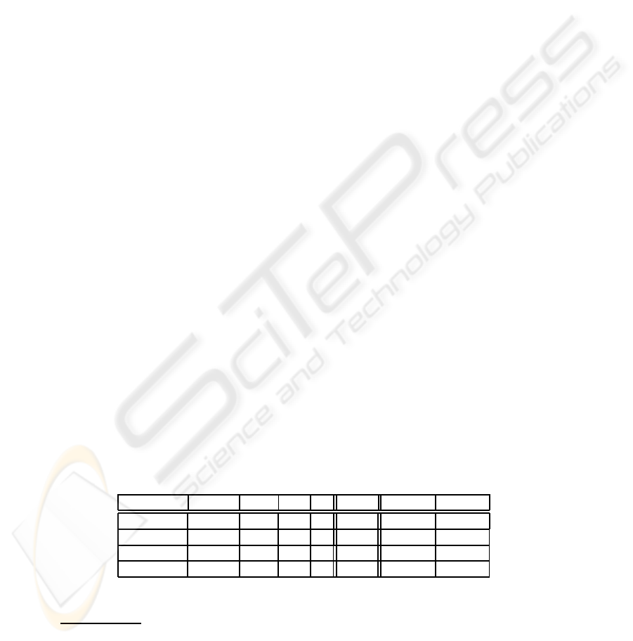
Table 1. Complexity attributes and calculation time (in seconds) for experimental subjects.
Specification Pages A4 Primes CD DD ViZ(s) EJB-A [s] EJB-B [s]
BB 2 34 10 5 4.6 7.0 6.5
Cinema 4 74 121 43 75.3 43.2 30.7
Petrol 3 65 192 177 152.9 51.9 38.7
Elevator 6 185 1,628 992 1,223.4 709.3 502.7
4
See [19] for more details on the meaning of specification clusters, slices, and chunks.
233
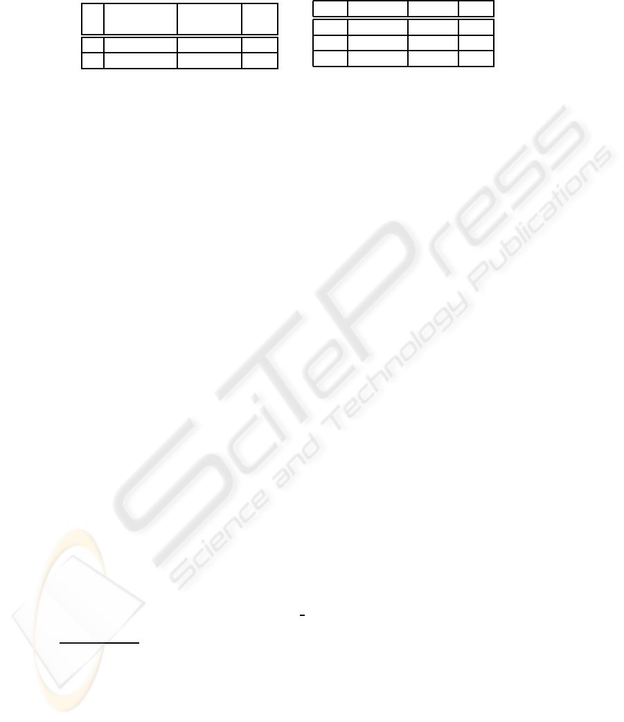
Table 2. Complexity, described by the number
of data (DD) and control dependencies (CD).
incl. overhead no overhead diff
in [s] in [s] (in %)
DD 139.2 93.3 -32.97
CD 343.6 232.5 -32.33
Table 3. Comparison of JDBC and EJB
access to the database.
Runs JDBC [ms] EJB [ms] Factor
100 781 5,158 6.60
1000 7,784 51,767 6.65
10000 88,463 526,956 5.96
5.2 Performance Considerations
The ViZ framework provides additional features (such as browsing the specification
graphically), but the calculation of dependencies (and thereinafter slices or chunks) is
time-consuming. Tab. 1 (right side) presents the time needed to calculate all dependen-
cies, for the ViZ environment and the new framework (for two different settings, called
EJB-A and EJB-B). For our approach we wanted to see whether there are some im-
provements or not. So, the performance
5
was explored thoroughly.
The reason for two settings was the inexplicable performance lack when working
with specifications of raising sizes. The experiences we gained are described here-
inafter. As most studies focus on the throughput of the system by varying the amount of
clients served by the EJB application [22,23], this chapter approach the subject from a
different angle (performance lacks due to database access of one client).
The performance of the system varied depending on the size of the specification,
which was expected. Complexity considerations showed that the runtime complexity
6
is in O(cs ∗ 2n
s
). Tab. 1 (right side) summarizes the time needed for the identifica-
tion/storage of all primes and dependencies. The most complex artifact is the Elevator
specification
7
, and after about 10 minutes it was analyzed and stored persistently for
later use. On the same setting this is about two times faster than done by ViZ [14]. But
we were eager to know why it took five minutes to store a bit more than 2600 data-sets.
We investigated further into this issue and made two important observations:
– Too much time is lost due to the EJB’s synchronization between the database and
Java’s internal objects.
– There is very high execution time latency between EJB queries and their corre-
sponding JDBC queries.
The measured times vary due to the different complexities of the specifications. But,
performance is lost due to the overhead of the relational and object-oriented mapping.
EJB can be seen as an additional layer between the DB and the implemented busi-
ness logic. Every synchronization contributes to an increase in processing time. To get
unique identifiers for objects (we used auto increment ID), one has to flush/synchroni-
ze the objects with those in the database. That this flush is costly was clear, but we
5
We used the same measurement settings: Intel(R) CP T2600 2.16GHz, 1GB RAM, Windows
XP and ServicePack 2
6
Here, cs is the number of different scopes, and n
s
is the number of prime elements.
7
There are 7,057 entries within the combines relation of the database: 1,984 data dependency,
3,256 control dependency and 1,817 scope information (see Fig. 4).
234

Fig.3. Time for storing primes, calculating scopes, and data and control dependencies.
wanted to know how much time is lost. We used the Elevator specification to measure
it, and found out that the overhead is about one-third of the time (see Tab. 2).
The second issue we were curious about was the difference between EJB and JDBC
when accessing the database. And indeed, we found a big time latencybetween EJB and
JDBC queries. Not surprising, JDBC was faster, but the differences were notable (see
Tab. 3). To measure it, we implemented the same requests with the EJB query language
and with JDBC statements
8,9
. Then, both requests were issued up to 1000 times
10
. We
found out that JDBC scales with the factor of about six times better than EJB.
So, although EJB (with entity beans and annotations within the entity bean classes)
produces a more readable code, performance decreases when one has to store many
objects per transaction which are, then, needed in ongoing processing steps. In our
framework this is the case when we have to store an object and need the unique ID
for storing the intermediate relation between those objects. The flushing/synchronizing
mechanism is the only but very expensive way for getting it.
Additionally, the performance evaluation was accomplished with updated measure-
ment characteristics
11
. This shows that upgrading the system is one and often the easiest
way to achieve better performance results of EJB application. Tuning the operating sys-
tem and platform is one factor suggested by Sun [24, p.95]. The evaluation showed that
with improved CPU power and additional working memory the performance of EJB
yields better results, as shown in Fig. 3 and Tab. 1 (settings A and B). However, inde-
pendently from the setting, the speed-up when accessing the database (see Tab. 4) stays
within the range of 5 to 7. Also the influence of the overhead remains constant (see
Tab. 5) at about 30-40%.
An evaluation of an earlier draft of the EJB specification from Jordan [25] shows also
significant performance differences between JDBC and EJB. As JDBC has to deal less
with object oriented abstractions, it performs well with high database access rates. An-
other way to get higher performance is to de-normalize the database schema [26].Un-
8
The query tested for two equal identifiers at different primes and joined two times over the
SyntaxElement, the CombinationType entities, and the combines and emd annotates SE rela-
tion. The database contained 2620 entries in the combines relation.
9
This evaluation was performed with 150 entries within the combines relation and 73 syntactical
elements (see Fig. 4).
10
Database internal optimizations, like cashes were, of course, disabled.
11
Measurement settings: Intel(R) Core(TM)2 CPU, T7200 @ 2.00GHz, 2 GB RAM
235
doubtedly, EJB yields advantages like transaction management, security mechanisms,
and scalability. It offers a comfortable way in implementing things. But this luxury does
not come for free.
Table 4. Comparison of JDBC and EJB
access to the database based on second
settings.
Runs JDBC [ms] EJB [ms] Factor
100 625 4,391 7.03
1000 6,315 43,485 6.89
10000 62,462 423,670 6.78
Table 5. Time (concept manifestation w/o
sync overhead) of setting two.
incl. overhead no overhead diff (in %)
in [s] in [s] (in %)
DD 92.20 56.63 -38.58
CD 234.53 158.19 -32.55
6 Conclusions
Concept location is a challenging task which also holds for the identification of con-
cepts within formal Z specifications. Once detected, they should be stored for future
use to save time when analyzing the artifacts again. For this reason a framework was
implemented that is able to identify and store concepts in a database. For its implemen-
tation the middleware technology EJB was utilized.
This paper introduces the architecture and evaluates the resulting framework. The
evaluation shows that it produces correct and useful results. However, the performance
of the framework was strongly influenced by EJB. We found out that the most im-
portant latency is due to the synchronization process between a bean objects and the
database. The comparison between JDBC and EJB shows a high factor of performance
loss. JDBC scales about six times better than EJB in terms of runtime. Additionally,
EJB implements an intermediate layer and, therefore, runs into performance latencies.
In a setting similar to our framework the evaluation shows that the use of EJB tech-
nologies is less suitable. EJB brings several maintenance advantages, but one has to
expect a performance loss that should not be neglected.
References
1. Hoare, C.A.R.: The emperor’s old clothes. Commun. ACM 24 (1981) 75–83
2. Nickel, U., Niere, J., Wadsack, J., Z¨undorf, A.: Roundtrip Engineering with FUJABA.
In Ebert, J., Kullbach, B., Lehner, F., eds.: Proceedings of 2nd Workshop on Software-
Reengineering (WSR), Bad Honnef, Germany (2000)
3. Jouault, F.: Loosely Coupled Traceability for ATL. In: Proceedings of the European Confer-
ence on Model Driven Architecture (ECMDA 2005), Workshop on Traceability. (2005)
4. Borland: The Rational Homepage. http://www.borland.com/us/products/together (2008)
5. Eclipse: Generative Modeling Techn. Homepage. http://www.eclipse.org/gmt/ (2008)
6. M¨uller, H.A., Tilley, S.R., Wong, K.: Understanding Software Systems Using Reverse Engi-
neering Technology Perspectives from the Rigi Project. In: CASCON’93. (1993) 217–226
7. Burnstein, I., Roberson, K., Saner, F., Mirza, A., Tubaishat, A.: A Role for Chunking and
Fuzzy Reasoning in a Program Comprehension and Debugging Tool. In: TAI-97, 9
th
Inter-
national Conference on Tools with Artificial Intelligence, IEEE press (1997)
236

8. Ebert, J., Kullbach, B., Riediger, V., Winter, A.: GUPRO – Generic Understanding of Pro-
grams An Overview. Electronic Notes in Theoretical Computer Science 72 (2002)
9. Ferenc, R., Beszedes, A., Tarkiainen, M., Gyimothy, T.: Columbus – Reverse Engineering
Tool and Schema for C++. In: IEEE International Conference on Software Maintenance,
Montreal, Canada (2002) 172–181
10. Korshunova, E., Petkovic, M., van den Brand, M.G.J., Mousavi, M.R.: CPP2XMI: Reverse
Engineering of UML Class, Sequence, and Activity Diagrams from C++ Source Code (Tool
Paper). In: Working Conference on Reverse Engineering (WCRE’06), Benevento, Italy
(2006)
11. Chen, K., Rajlich, V.: RIPPLES: Tool for Change in Legacy Software. In: IEEE International
Conference on Software Maintenance, Los Alamitos, CA, USA, IEEE Computer Society
(2001) 230
12. Xie, X., Poshyvanyk, D., Marcus, A.: 3D Visualization for Concept Location in Source
Code. In: Proceedings of 28th IEEE/ACM International Conference on Software Engineer-
ing (ICSE’06). (2006) 839–842
13. Poshyvanyk, D., Marcus, A.: Combining Formal Concept Analysis with Information Re-
trieval for Concept Location in Source Code. In: Proceedings of the 15th IEEE International
Conference on Program Comprehension (ICPC2007). (2007) 37–48
14. Bollin, A.: Specification Comprehension Reducing the Complexity of Specifications. PhD
thesis, Institute for Informatics-Systems, University of Klagenfurt (2004)
15. Wakounig, D.: Reverse Engineering of Typed Rulebased Systems – Dependency Analysis
and Comprehension Aspects. PhD thesis, University of Klagenfurt (2008)
16. Pohl, D.: Specification Comprehension – Konzeptverwaltung am Beispiel zustandsbasierter
Spezifikationen (in German). Master’s thesis, University of Klagenfurt, Software Engineer-
ing and Soft Computing (2008)
17. Rajlich, V., Wilde, N.: The Role of Concepts in Program Comprehension. In: International
Workshop on Program Comprehension, IEEE Computer Society (2002) 271–278
18. Spivey, J.: The Z Notation. C.A.R. Hoare Series. Prentice Hall (1989)
19. Bollin, A.: Concept Location in Formal Specifications. Journal of Software Maintenance
and Evolution: Research and Practice 20 (2008) 77–104
20. Burke, B., Monson-Haefel, R.: Enterprise JavaBeans 3.0. O’Reilly (2006)
21. Chang, J., Richardson, D.: Static and Dynamic Specification Slicing. In: In Proceedings of
the Fourth Irvine Software Symposium, Irvine, CA. (1994)
22. Zhang, Y., Liu, A., Qu, W.: Comparing industry benchmarks for J2EE application server:
IBM’s trade2 vs Sun’s ECperf. In: ACSC ’03: Proceedings of the 26th Australasian computer
science conference, Darlinghurst, Australia, Australia, Australian Computer Society, Inc.
(2003) 199–206
23. Leff, A., Rayfield, J.T.: Improving Application Throughput With Enterprise JavaBeans
Caching. Distributed Computing Systems, International Conference on 0 (2003) 244
24. Microsystems, S.: Sun Java System Application Server 9.1 Performance Tuning Guide. EJB
Performance Tuning. In: http://docs.sun.com/app/docs/doc/819-3681/6n5srlhkj?a=view, Inc.
4150 Network Circle Santa Clara, CA 95054 U.S.A., Sun Microsystems Documentation
(2007)
25. Jordan, M.: A Comparative Study of Persistence Mechanisms for the Java Platform. In:
http://research.sun.com/techrep/2004/smli tr-2004-136.pdf, Inc. 4150 Network Circle Santa
Clara, CA 95054 U.S.A., Sun Microsystems Documentation (2004)
26. Yao, S.S., Hiriart, R., Barg, I., Warner, P., Gasson, D.: A case Study of Applying Object-
Relational Persistence in Astronomy Data Archiving. In Shopbell, P., Britton, M., Ebert, R.,
eds.: Astronomical Data Analysis Software and Systems XIV. Volume 347 of Astronomical
Society of the Pacific Conference Series. (2005) 694ff
237

Fig.4. The four different panes of the database model.
238
