
C3: A METAMODEL FOR ARCHITECTURE DESCRIPTION
LANGUAGE BASED ON FIRST-ORDER CONNECTOR TYPES
Abdelkrim Amirat and Mourad Oussalah
LINA Laboratoy CNRS, University of Nantes, France
Keywords: Architecture, First class connector, Connection manager, Modeling software architecture, C3 Metamodel.
Abstract: To provide hierarchical description from different software architectural viewpoints we need more than one
abstraction hierarchy and connection mechanisms to support the interactions among components. Also,
these mechanisms will support the refinement and traceability of architectural elements through the different
levels of each hierarchy. Current methods and tools provide poor support for the challenge posed by
developing system using hierarchical description. This paper describes an architecture-centric approach
allowing the user to describe the logical architecture view where a physical architecture view is generated
automatically for all application instances of the logical architecture.
1 INTRODUCTION
The representation of software architecture is based
on the concepts of component (loci of computation),
connector (loci of communication), and
configuration (arrangement of components and
connectors, and properties of that arrangement) in
order to describe the structure of the system at a
higher level of abstraction than objects or lines of
code. This representation provides several
advantages over the life cycle of a software (Garlan
et al., 2000).
Although the use of connectors is widely
accepted at the conceptual level, their explicit
representation at the implementation level is not
always left to be necessary. However, we feel that
distinct conceptual entities should correspond to
distinct implementation entities, so that they can
truly become first-class and be manipulated as such.
In fact, as argued in (Medvidovic et al., 2000), the
current level of support that architecture description
languages (ADLs) provide for connector building is
still far from the one awarded to components. For
instance, although a considerable amount of work
can be found on several aspects of connectors
(Dashofy et al., 2005; Medvidovic et al., 2007; and
Garlan et al., 2000), further steps are still necessary
to achieve a systematic way of constructing new
connectors from existing ones. Yet, the ability to
manipulate connectors in a systematic and controlled
way is essential for promoting reuse and incremental
development, and to make it easier to address
complex interactions.
Certainly, having a representation of the software
architecture allows an easy exchange between the
architect and programmer. Also, during the phases
of maintenance and evolution, this representation
helps to locate defects and reduces the risk of
improper assembly of a new feature in the system. In
addition, the distinction which exists between
components and connectors allows a more explicit
representation between the functional aspects and
these of communication and therefore, makes the
system easier to understand and to change. Finally,
architecture-based components are also useful to
facilitate the reuse of certain parts of the system
represented by configurations (Garlan et al., 2000).
In contrast the industrial world, which offers
components strongly linked to servers, systems or
models owners (Dashofy, 2005), the academic
approach is interested in formalizing the notion of
software architecture language. The ADLs provide a
high level of abstraction for the specification and
development of software systems.
In this article, we take a step towards this goal by
proposing a metamodel for the description of
software architecture called C3 (Component,
Connector, and Configuration). The specificity of
this metamodel based on the definition of two types
of architecture. A logical architecture defined by the
user and a physical architecture built by the system
and conforms to the logical architecture. The
76
Amirat A. and Oussalah M. (2009).
C3: A METAMODEL FOR ARCHITECTURE DESCRIPTION LANGUAGE BASED ON FIRST-ORDER CONNECTOR TYPES.
In Proceedings of the 11th International Conference on Enterprise Information Systems - Databases and Information Systems Integration, pages 76-81
DOI: 10.5220/0001957500760081
Copyright
c
SciTePress
metamodel will make its contribution towards the
following objectives: 1- provide a higher abstraction
level for connectors in order to make them more
generic and more reusable; 2- take into account the
semantics of several types of relationships. In our
case; we explore the association relationship
between components, the composition relationship
among architectural elements, and the propagation
relationship to describe software systems at different
levels of details; 3- by using the physical and the
logical architecture, we can separate the functional
aspects of architectural elements and the non-
functional aspects related to the management of their
connections and consistency.
After this introduction and the motivations of our
research, the remainder of this article is organized as
follows: In section 2 presents the concept of a
logical architecture with the key elements of the
proposed metamodel. The physical architecture is
defined in section 3. The last section concludes this
work.
2 LOGICAL ARCHITECTURE
The large majority of ADLs consider components as
entities of first class. So, they make distinction
between component-types and component-instances.
However, this is not the case with other concepts
such as connectors and configurations. In our
metamodel we consider each concept recognized by
the C3 metamodel as architectural element of the
first class citizen. So, each architectural element
maybe positioned on one of the three abstraction
levels defined in the following section. We believe
that it is necessary to reify the core architectural
elements in order to be able to represent and
manipulate them and let them evolve easily.
2.1 Abstraction Levels
In our approach, software architectures are described
in accordance to the first three levels of modelling
defined by the OMG. The application level (A0)
which represents the real word application (an
instance of the architecture), the architecture level
(A1) which represents the architecture model and the
meta-architecture level (A2) which represents the
meta-language for the description of the logical
architecture.
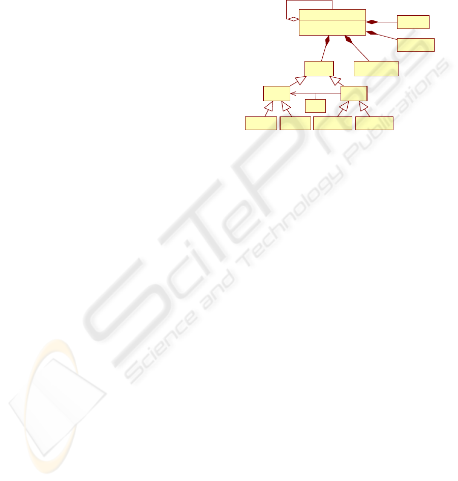
2.2 C3 Architectural Elements
An architectural element may have several
properties as well as constraints on these properties,
as it may have one or more possible
implementations. The interaction points of each
architectural element with its environment are the
interfaces. Each architectural element is defined by
its interfaces through which they publish its required
and provided services to and from its environment
(Figure 1).
ArchitecturalElement
+name
composed of
0..*
1
implem e n tation
realised by
1
1..*
Co ns tra i nt es
1
0..*
1
0..*
Properties
1
1..*
Inter face
Port Service
RequiredService ProvidedService
Use
RequiredPort ProvidedPort
Figure 1: Structure of an architectural element in C3.
2.2.1 Component
A component is that it is a software unit with
provided services and required services. The
provided services are operations performed by the
component. The required services are the services
needed by the component to produce the provided
services. The interface of a component consists of
the specifications of its provided and required
services. It should specify any dependencies
between its provided and required services.
2.2.2 Connector
Connectors are architectural building blocks used to
model the interactions between components and
rules that govern these interactions. They correspond
to lines in box-line descriptions. Unlike components,
connectors may not correspond to compilation
entities. However, the specifications of connectors in
an ADL may also contain rules to implement a
specific type of connectors. Current ADLs can be
classified into three different kinds: ADLs without
connectors, ADLs with predefined set of connectors,
and ADLs with explicit connector types.
2.2.3 Configuration
A configuration represents a graph of components
and connectors. Configuration specifies how
components are connected with connectors (Figure
2). This concept is needed to determine if the
components are well connected, whether their
C3: A METAMODEL FOR ARCHITECTURE DESCRIPTION LANGUAGE BASED ON FIRST-ORDER
CONNECTOR TYPES
77
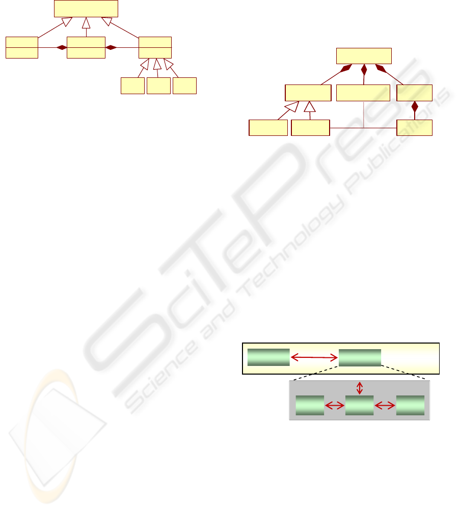
interfaces agree, and so on. A configuration is
described by an interface which enables the
communication between: the configuration and its
external environment, and the configuration and its
internal components.
ArchitecturalElement
Configura tio n
+name
Component
+name
Connecto r
+name
1
1..*
1
1..*
ECCACCDC
Figure 2: Component, connector, and configuration in C3.
2.3 Connectors in C3 Metamodel
A connector is mainly represented by an interface
and a glue specification (Amirat, 2007). Basically,
the interface shows the necessary information of the
connector, including the number of interaction
points, service type that a connector provides,
connection mode, transfer mode etc. In C3
interaction points of an interface are called Ports. A
port is the interface of a connector intended to be
tied to a component interface (a component’s port).
In the context of the frame, a port is either a
provided or a required port. A provide port serves as
entry point to a component interaction represented
by a connector type instance and it is intended to be
connected to the require port of a component (or to
the require port of another connector). Similarly, a
require port serves as the outlet point of a
component interaction represented by a connector
type instance and it is intended to be connected to
the provide port of a component (or to the provide
role of another connector). The number of ports
within a connector denotes the degree of a connector
type. For example, in client-server architecture a
connector type representing procedure call
interaction between client and server entities is a
connector with degree two. The glue specification
describes the functionality that is expected from a
connector. It represents the hidden part of a
connector. The glue could be just a simple protocol
links ports or it could be a complex protocol that
does various operations including linking,
conversion of data format, transferring, adapting,
etc.
2.3.1 Connector Structure
attachment links (Figure 3). So, the application
builder will have to spend no effort in connecting
connectors with its compatible components and/or
configurations. Consequently, the task of the
developer consists only in choosing from the library
the suitable type of connectors where its interfaces
are compatible with the interfaces of
component/configuration types of which are
expected to be assembled.
Connector
Our contribution at this level consists in enhancing
the structure of connectors by encapsulating the
Interface Connection Glue
Port
Se rvice Role
Figure 3: Connector structure.
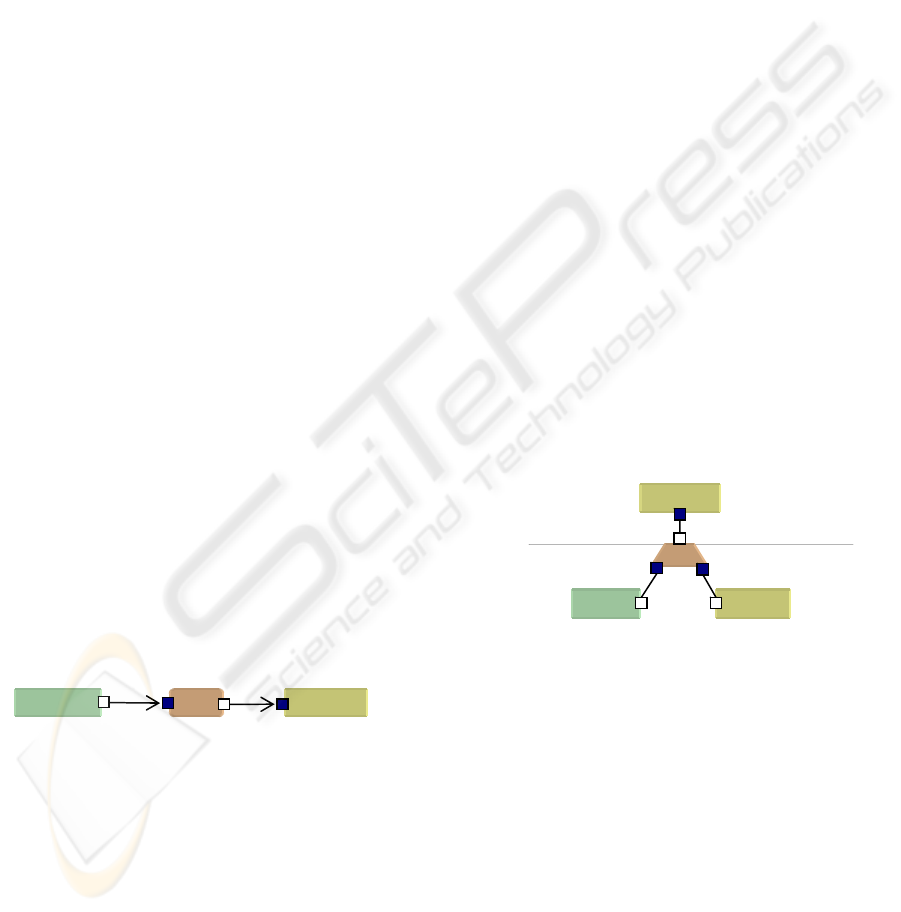
In order ies of C3
metamodel a case study is going to be used
thr
Figure ent–se itectu
In a p a new
structure of a connector where attachment are
enc
to illustrate the propert
oughout the paper. The case study is a client-
server configuration (CS-config) organized around a
client-server relationship. In this configuration we
have a client and a server. The server component
itself is defined by a configuration (S-config) whose
internal components are Coordinator (Coor.),
securityManager (SM) and dataBase (DB). These
elements are interconnected via connector services
that determine the interactions that can occur
between the server and client on one hand and
between the server and its internal elements on the
other hand (Figure 4).
4: Cli rver arch re.
revious work we have introduced
apsulated inside connectors and having well
defined connector interfaces with previously known
element types to be connected by each connector
type components and/or configurations are
assembled in an easy and coherent way in the form
of an architectural puzzle (Lego Blocks) without any
effort to describe links among components and
CS-
onfig. C
-Config. S
Client
Server
SM DB
Coor.
ICEIS 2009 - International Conference on Enterprise Information Systems
78
2.3.2 Connector Taxonomy
In C3 metamodel we have defined three connector
Connection Connector (CC). This type of
ame ({X
i
.requiredPort}, {Y
j
.providedPort})
/
k
),
aximum number of
ele
n
con
(portC1, portS1);
Figure 5: Connector CC1 in client-server architecture.
Composition/Decomposition Connector (CDC).
semantic roles with two different glue protocols.
});
X
dPort );
nn rts,
t r
cor
pectively used
to he
ser
Figure 6: Possible links of CDC1 connector.
Expansion/Compression Connec th
ECC en a
i
Name ({Y .requiredPort}, X.providedPort);
≤ number of internal elements.
connectors or between configurations and
connectors (Amirat, 2007).
types: the connection connector, the composition
decomposition connector, and expansion
compression connector. The signature of each
connector type is defined by: the requiredInterf
representing all required ports and services and
providedInterf representing all provided ports and
services of a connector. Where each service can uses
one or more ports of the same interface. In the
following we give the exact function of each type of
connector in C3 metamodel.
connector is used to connect components and
configurations belonging to the same level of
hierarchy. The ports of this type of connector can be
“required” or “provided”. The signature of a CC
connector is:
Connector CC N
where X
i
, Y
j
⊂
{component, configuration},
X
i
, Y
j
⊂ L
k
; / the same hierarchical level (L
With i = 1, 2, .., M ; j = 1, 2, .., N,
(M+N) represents the m
ments which can be linked by CC connector. The
mapping between the inputs and outputs is described
by the glue defined inside of the connector.
Figure 5 represents the CC1 connectio
nector type used to link a client component with
s-config configuration of the previous example. This
type connector has two ports: portC1 in client side
and portS1 in server side. Hence, the interface CC1
will be defined as follows:
Connector CC AC1
This type of connector is used to realize a top-down
refinement (i.e. to link a configuration with its
internal elements) also we call this relationship a
decomposition model. Likewise CDC connector can
be used to realize bottom-up abstraction (i.e. to link
a set of elements to their container or configuration
also we call this relationship a composition model.
However, this type of connectors can play two
// decomposition of a configuration X to its internals
Connector CDC Nom (X.requiredPort , { Y
i
.providedPort
// composition of Y elements to constitute a configuration
i
Connector CDC Nom ( {Y
i
.requiredPort} , X.provide
X is a configuration, Y
i
⊂ {component, configuration},
i =1,..,N ; X
⊂ L
k
and Y
i
⊂ L
k-j
, L is the hierarchical level.
Thus, a CDC co ector will have (N+1) po
where N is he numbe of internal elements in the
responding configuration. This type of connector
has the following functions: first it allows us to
shape the genealogical tree of the different elements
deployed in an architecture, second it enables a
configuration to spread information to all these
internal elements without exception (to-down
propagation) and inversely (i.e. it allows any internal
element to send information to its configuration.
Figure 6 represents CDC1 a decomposition
composition connector type used to link client-
server configuration (CS-config) defined at the
hierarchical level (L
2
) with its internals namely
client component (Client) and server configuration
(s-config) defined at the lower hierarchical level
(L
1
). Consequently, the interface of CDC1 connector
type will be specified as follows:
Connector CDC CDC1 ( portCS, portC2, portS2);
portC2, portS2, and portCS are res
connect CDC1 with the client component, t
ver configuration, and client-server configuration
(CS-config).
tor (ECC).
is used to establish a service link betwe
e
configuration and its internal elements. Also, ECC
can be used as an expansion operator of services to
several sub-services and it can be used in reverse as
a compression operator of set of services to a global
service. The CDC may have an interface for
expansion and another for compression. So, these
interfaces are defined as follows:
// expansion
Connector ECC Name (X.requiredPort, {Y .providedPort });
// compression
Connector ECC
i
tion, Y
⊂ {component, configuration}, X is a configura
i =1,2,..,N, and N
CS-Config
S-Config
Client
CDC1
L
2
portCS2
L
1
portS2 portC2
CC1
Client
portS1portC1
S-Config
C3: A METAMODEL FOR ARCHITECTURE DESCRIPTION LANGUAGE BASED ON FIRST-ORDER
CONNECTOR TYPES
79
yp ng
e or
p r for
exp
: ECC1 connector chitecture.
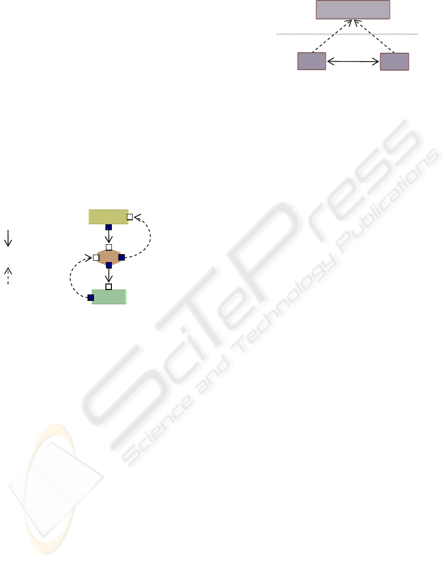
3 P
image is built in the form of a graph whose nodes
The physical architecture is described using only
d t
instance level as illustrated in Figure 8.
Figure 8: Abstraction levels in physical architecture.
In t odel l we ha he co ections
manager type enc ing e ation
on the links that a component onfiguration m y
ha
a name and has for attributes as follows:
Ele name of the
arc this CM;
CC ted to the
ele C_link: the
nam he element
ions on the connections manager are:
n architectural element
ion level the
assoc created in the
alled at
on is built by the user, the
cor
X
⊂ L
k
et Y
i
⊂ L
k-1
; L is the hierarchical level.
ECC connector t e can be implemented usi
eith r single glue for one function (expansion
com ression) o using two separate glues
ansion and compression functions. This will
depend on the design decision. Figure 7 illustrates
the connector type ECC1 which allows exchange of
information between the server configuration (S-
Config) and the coordinator component (Coor.). To
achieve a bidirectional communication between the
server and the coordinator, ECC1 must have the
following ports: portS3 and portCo1 are used to
ensure the expansion function from the server to
coordinator. portCo2 and portS4 are used to ensure
compression function. So, the interface of this ECC1
connector type will be as follows:
Connector ECC ECC1(portS3,portCo1,portS4, portCo2);
Figure 7 in CS ar
HYSICAL ARCHITECTURE
The physical architecture is a memory image of the
application instance of the logical architecture. This
are instances of a connections manager. Each
instance created corresponds to a component or a
configuration instantiated to construct the real
application. Nodes of this graph are connected by
arcs. We have three types of arcs. Each type of arc
corresponds to specific type of connector. The
physical architecture is built to serve as support for
updating and evolution operations of the application
instance like addition, removal, and replacement of
elements in the application instance.
3.1 Connections Manager (CM)
htwo levels of abstractions; the model level an e
The physical architecture corresponding to the
application instance of client-server architecture is
illustrated in Figure 9. In this application we assume
having two clients connected to a single server.
Once the applicati
he m evel
apsulat
ve t nn
nt informall differ
or a c a
ve with its environment. Each CM is identified by
ConnectorManager Name {
ElementName: string;
CDC_Link:list_of_CMs;
CC_Links:list_of_CMs;
ECC_Link:list_of_CMs}
mentName: represents the
hitectural element associated with
_Links: list of CC names connec
ment associated with this CM; CD
e of the CDC connected to t
associated with this CM; ECC_Link: the name of the
ECC connected to the element associated with this
CM;
3.2 Operations on
Connections Manager
Operat
• Instantiation: Whenever a
is instantiated at the applicat
iated CM is automatically
physical architecture.
• Installation: each time a connector is inst
the application level between a set of element
instances, so the attributes of the associated CMs
are updated with the necessary information about
this connector instance.
• Propagation: the mechanism of propagation is
used to update information about links needed
between CMs. These links are published by the
interface of the connector installed at the
application level.
responding physical architecture is also built in
parallel. Thereafter if we need to maintain or evolve
Instance level
(
A
0
)
Model level
(
A1
)
Link
Instance-Of
Connections Manager
CM1
CM2
S-Config
ECC1
Coor.
portS3
portCo1
portS4
portCo2
Com
p
ression
Ex
p
ansion
Expansion
Compression
ICEIS 2009 - International Conference on Enterprise Information Systems
80
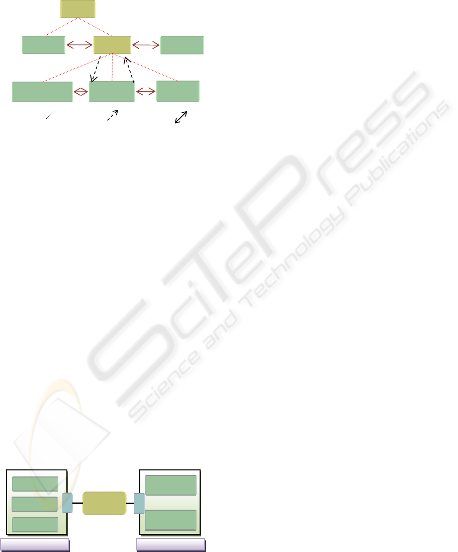
Figure 9: Physique architecture of CS application.
rep ogical ture
(LA) a
rela
C3 re
represented by two components and the relationship
bet
evel.
s corresponding to all
Figure 10: Architectures relationship. LI: logical interface;
PI: physical interface.
4 CONCLUSIONS
Our h y n architectural
meta describ architectures, where
a log itecture is described tect
using most commonly accepted concepts by all
components, d
he structure of connectors.
This new structure allows us to assemble connectors
ed in its interface.
s of connectors: CC
Garlan, D., Monroe, R.T., and Wile, D., 2000. Acme:
Architectural Description Component-Based Systems,
Component-Based Systems.
Press, pages 47-68.
Medvidovic, N. and. Taylor, R.N., 2000. A Classification
Me .N., 2007.
the application we must locate the concerned
elements on the physical architecture using a graph
searching routines and a graph updating operations
like add (node), delete (node) or replace (node).
approac
model to
is defined b a
e software
ical arch by the archi
CM_CS
CMserver
CMclient1
ADLs namely connectors an
Finally we can resent the l architec
nd the physical architecture (PA) and the
tionship between them by a model described in
metamodel where the LA and the PA a
ween the by a CC connector (Figure 10). Any
action performed at the LA level causes a sending a
message to the PA. This message will be interpreted
as an action to be performed by the PA. So, among
these actions we have:
• A component instantiation at the LA level causes
sending a message “CM_creation” to the PA.
When this message is received by the PA a CM
instance will be created to represent this
component at the PA l
• A connector instantiation at the LA level causes
sending a message “CM_connection” from LA to
PA. When this message is received by the physical
architecture a set links are created to link
connection manager instance
components connected by this connector instance.
• Any updating action at the logical architecture
causes sending a message “CM_update” from LA
to PA. So, this message will be interpreted as set
of updating operations performed to rearrange
links among the corresponding CMs.
configurations, and we found interesting to give a
new structure for connectors in which attachments
are encapsulated within t
only with elements that are defin
We have identified three type
connector which refer to the links among elements
belonging to the same level of decomposition, CDC
connector which refer to the links between a
configuration and its internal elements, ECC
connector which refer to the links used to realize any
transformation of information or data exchanged
between a configuration and its internal elements.
Also, we have defined a physical architecture as
a graph whose nodes are CMs associated with
architectural elements and arcs represent links that
correspond to the connectors. The physical
architecture reflects the application architecture
which is an instance of the logical architecture and
serves as a support for maintenance and evolution
operations applied on architecture of the application.
REFERENCES
Amirat, A., Oussalah, M., and Khammaci, T., 2007.
Towards an Approach for Building Reliable
Architectures. In Proceeding of IEEE IRI’07, Las
Vegas, Nevada, USA, pages 467-472.
Dashofy, E., Hoek, A.v.d., Taylor, R.N., 2005. A
comprehensive approach for the development of
XML-based software architecture description
languages. Trans. on Soft. Eng. Methodology.
Foundations of
Cambridge University
and Comparison Framework for Software Architecture
Description Languages. IEEE Transactions on
Software Engineering, volume 26, issue 1.
dvidovic, N., Dashofy, E., and Taylor, R
Moving Architectural Description from Under the
Technology Lamppost. Information and Software
Technology, volume 49, issue 1, pages 12-31.
A
0
Level
Instance Level
A
1
Level
A
2
Level
System Level
Connection
Connector
LI
PI
Legend: : CDC : ECC : CC
CM
coordina
t
o
r
CM
securit
y
Mana
g
e
r
CM
dataBase
CMclient2
Lo
g
ical Architecture
Physical Architecture
C3: A METAMODEL FOR ARCHITECTURE DESCRIPTION LANGUAGE BASED ON FIRST-ORDER
CONNECTOR TYPES
81
