
AUTOMATIC GENERATION OF TEST CASES IN SOFTWARE
PRODUCT LINES
Pedro Reales, Macario Polo
Alarcos Group, Dept. of Information Systems and Technologies, U. of Castilla-La Mancha
Paseo de la Universidad/4, 13071, Ciudad Real, Spain
Beatriz Pérez Lamancha
Centro de Ensayos de Software (CES), Institute of Computation,University of the Uruguay Republic
Julio Herrera y Reissig 565, 11300, Montevideo, Uruguay
Keywords: Oracle, Automation, Testing, Test Cases, Software Product Line, Transformation algorithms.
Abstract: This paper describes a method to automatically generate test cases with oracle in software product lines,
where the management of variability and traceability are two indispensable requirements. These character-
istics may be quite useful for the processing and automatic addition of the oracle to test cases, which is one
of the main problems found, not only in the context of software product lines, but also in general testing lit-
erature. The paper describes a simple, but effective, way to deal with this problem, based on annotations to
precode artifacts, metamodelling and transformation algorithms.
1 INTRODUCTION
In the context of Software Engineering, a Software
Product Line (SPL) represents “a set of software-
intensive systems sharing a common, managed set of
features that satisfy the specific needs of a particular
market segment or mission and that are developed
from a common set of core assets in a prescribed
way” (Clements and Northrop, 2002). According to
(McGregor et al., 2002), products in a line are char-
acterized, on the one hand, by their similitude with
respect to common characteristics and, on the other
hand, by the diversity that each product introduces
with respect to the line.
Two development processes are distinguished in
the construction of a line: Domain Engineering,
related to the development of the core assets, and
Product Engineering, related to the implementation
of concrete products. The requirements of the line
are described at the domain level, and will be used at
the product level. Each product is distinguished
from the line in a series of variability points. The
elements proceeding from the line and the particular
characteristics of the product are integrated for
implementing the final products.
This paper presents a method for the automatic
generation of “oracled” test cases in SPL. The idea
starts from the reusing capabilities at the domain
engineering level, whose test cases can be used to
derive test cases for the different products. For this,
maintaining coherence and traceability among the
different artifacts is essential. Several proposals ex-
ist to automate the generation of test cases in prod-
uct line contexts; however, in all of them the prob-
lem of dealing with the oracle is unresolved. Ac-
cording to (Bertolino, 2007), the automatic manipu-
lation and generation of oracles is a central research
line in the testing area, and this work introduces a
meaningful contribution in this respect.
The paper is organized as follows: section 2 de-
scribes some pending challenges with respect to the
oracle and includes a brief revision of some works
related to testing and testing in software product
lines. Section 3 shows and illustrates the product
line construction method. Section 4 describes the
metamodelling aspects of the work. Finally, Section
5 includes some conclusions, lessons learned and
future work.
124
Reales Mateo P., Polo M. and Pérez Lamancha B. (2009).
AUTOMATIC GENERATION OF TEST CASES IN SOFTWARE PRODUCT LINES.
In Proceedings of the 11th International Conference on Enterprise Information Systems - Information Systems Analysis and Specification, pages
124-130
DOI: 10.5220/0001983101240130
Copyright
c
SciTePress

2 RELATED WORK
One the main difficulties in software testing research
and which, according to (Bertolino, 2007), consti-
tutes an important obstacle to any advance in its
automation, is the description of the oracle, which is
the mechanism provided to each test case to deter-
mine, after its execution, whether the system under
test passes or fails the test.
(Baresi and Young, 2001) present a wide state of
the art with respect to the oracle problem. Most of
the proposals they analyze consist of the insertion of
instructions in programs which perform any kind of
checking or use formal descriptions of the programs.
However, their writing and maintenance may be so
complex as the writing and maintenance of the self
program.
In her roadmap about testing research, (Harrold,
2000) suggests the use of “precode artefacts”, such
as design or requirements documents, architectural
specifications, state machines etc., a quite stimulat-
ing approach in the context of SPL. In this respect,
several authors have proposed strategies to obtain
test cases from different types of diagrams as
(Basanieri et al., 2002, Offutt et al., 2003)
In (Bertolino et al., 2004) the use cases are
adapted to SPL and the test cases are derived manu-
ally from these. In (Olimpiew and Gomaa, 2006)
test models are created from use cases using activity
diagrams, decision tables and test templates. Related
to test case derivation from sequence diagrams in
SPL, in (Nebut et al., 2003) is proposed a method in
which behavioural test patterns (behTP) are obtained
from high-level sequences which are used to auto-
matically generate test cases specific to each prod-
uct.
In general, the goal of deriving test scenarios and
test cases from state machines, interaction diagrams,
etc. has been significantly researched over the last
years, and important results have been obtained.
However there is a lack of advances in the treatment
of the oracle.
As with some of the reviewed works, our pro-
posal makes it possible to obtain test cases from
interaction diagrams, both at domain and product
engineering. A significant contribution of this work
is the possibility of generating concrete oracles (for
specific products of the line) from some annotations
introduced in the sequence diagrams.
3 DESIGN OF THE PRODUCT
LINE
Following some ideas of the authors mentioned in
the previous section, the product line design starts
with use cases (to represent and describe the re-
quirements) and sequence diagrams (to represent the
scenarios of the use cases). Additionally, sequence
diagrams are annotated with a description of the
states that the instances involved in the diagram
must reach during execution. State descriptions
(which may or may not come from state machines)
will be used later to deal with oracles.
A single example will be used to illustrate the
product line building method and the test case gen-
eration strategy. Later, in Section 0, the metamodels
used to represent the artefacts and the algorithms
applied to execute the transformations will be pre-
sented.
3.1 Use Case Design in a SPL
Let us suppose we need to build a product line to
play different Board games (Trivial, Chess, Ludo,
etc.) with a computer. There will be a games server
which will receive client connections, each one op-
erated by a human player, which takes the game
decisions he/she considers. According to the de-
scription, there exist two systems in this product
line: the client applications (which are communi-
cated with the human player) and the server system
(which interacts with the clients).
For each use case, the classes involved in its
execution are identified and categorized (bounda-
ries, controllers and entities). In this example, one of
the server use cases is Piece movement, which is
executed when the client sends a piece movement to
the server. In order to keep the example simplified,
we assume that two classes are sufficient to manage
this use case: “Game” (an entity class) and “Con-
trol” (an use case controller). As with other devel-
opment methodologies, a textual description of use
cases is given in a template.
Although use cases are not directly used to gen-
erate test cases, work in product lines imposes the
joint and rigorous management of traceability and
variability.
In this respect, several proposals exist to deal
with variability during development, such as (Berto-
lino et al., 2004), who describe the PLUCs (Product
Line Use Cases) that hold the traditional information
of use cases plus the variability to be supported by
the described functionality. They use the labels Al-
AUTOMATIC GENERATION OF TEST CASES IN SOFTWARE PRODUCT LINES
125
ternative (different execution alternatives depending
on the product), Optional (optional executions de-
pending on the product) and Parametric (different
executions depending on the values of other labels).
Thus, two new sections are added to the use case
description template: Scope, to know what products
will include the use case; and Variability, which
defines the variation points and the labels. Event-
flows may be annotated with the labels which will
be defined in this section.
For our work, the labels Alternative and Op-
tional have been redefined, and the Scope label has
been created. The main difference with Bertolino is
that labels are always parameterized with the label
defining the use case scope; in this way, all variation
points depend on the products supported by the use
case.
Figure 1 shows the textual description of the
Piece movement use case (for singleness, it only
includes the normal flow of events).
In the example, the Scope section says that the
use case is applicable to any product (as a counter-
example, the use case Dice throwing is not applica-
ble to the Chess product), and the Variability section
define the labels: MP0 denotes the use case scope;
MP1 denotes an alternative piece of functionality
and MP2 and MP3 represent an optional piece of
functionality. Note that labels MP1 to MP3 are ref-
erenced in the description of the normal flow of
events.
3.2 Sequence Diagrams Design in a
SPL
Once the use case has been described in the tem-
plate, the corresponding sequence diagrams are
built, drawing one for each event-flow in the use
case.
In this case, variability may be present both in
messages and objects. Messages may be labelled as
Optional (they appear in some products, but not in
others), Mandatory (they are present in all the prod-
ucts, but their implementation depends on the prod-
uct) and Fixed (they appear in all the products with
the same implementation). If an instance sends or
receives variable messages, the corresponding object
may be also annotated with the Variable label.
3.2.1 State Descriptions for the Oracle
Since sequence diagrams will be the main artefact to
generate test cases, and these will not be complete if
they lack the oracle, some means to represent and
manipulate the oracle is required. For this issue,
when sequence diagrams are constructed, the ex-
pected and relevant states of the objects involved in
the diagram must have been described, and will be
used to annotate the diagram: states are described in
terms of the values of the class attributes and com-
plement the description of the scenarios in the se-
quence diagram: when an object receives a message,
the expected state of the instance is annotated. Thus,
the sequence diagram holds all the information re-
quired to obtain the testing scenarios and the ora-
cles.
The fact of adding this kind of annotation to the
scenario is a very simple idea, but has shown to be
powerful for the further addition of the oracle to test
cases, both at Domain and Product Engineering lev-
els.
State descriptions may also require variability
annotations, since some class fields may appear only
in some products (for example, there are no dice in
the Chess product).
USE CASE
Piece movement
OBJECTIVE
Moving a piece
SCOPE
Any product [MP0]
PRECONDITIONS
The client has the turn
SUCCESS FINAL CONDITION
A piece has been moved
FAILURE FINAL CONDITION
There is no movement
ACTORS
Client
TRIGGER
The client executes the
movement
NORMAL FLOW OF EVENTS
1. The client sends the movement order to control
2. Control passes the movement to game.
3. {[MP1] Game checks the legality of the movement. Cross-
Reference. Legality checking}
4. {[MP2] Control orders game to take a piece (if necessary).
Cross-Reference. Piece taking}
5. Control notifies the movement to the opponents. Cross-
Reference. Update clients.
6. {[MP3] Control asks game if the turn must be passed}
7. {[MP2] Control passes the turn. Cross-Reference. Pass
turn}
VARIABILITY
MP0: [1 of n]. Scope
0 - Chess, 1 – Checkers, 2 – Ludo, 3 – Trivial
MP1:[1 of n]. Choice
If MP0=0
Check the movement is correct according to the moved
piece
If MP0=1
Check the movement is correct in diagonal
If MP0= 3 || MP0=2
Check the final position is coherent with the result of the
dice obtained before the movement
MP2: [0..1 of 1]. Optional
When MP0= 0 || MP0=1 || MP0=2
MP3: [0..1 of 1]. Optional
When MP0= 2
Figure 1: Textual description of Piece movement.
ICEIS 2009 - International Conference on Enterprise Information Systems
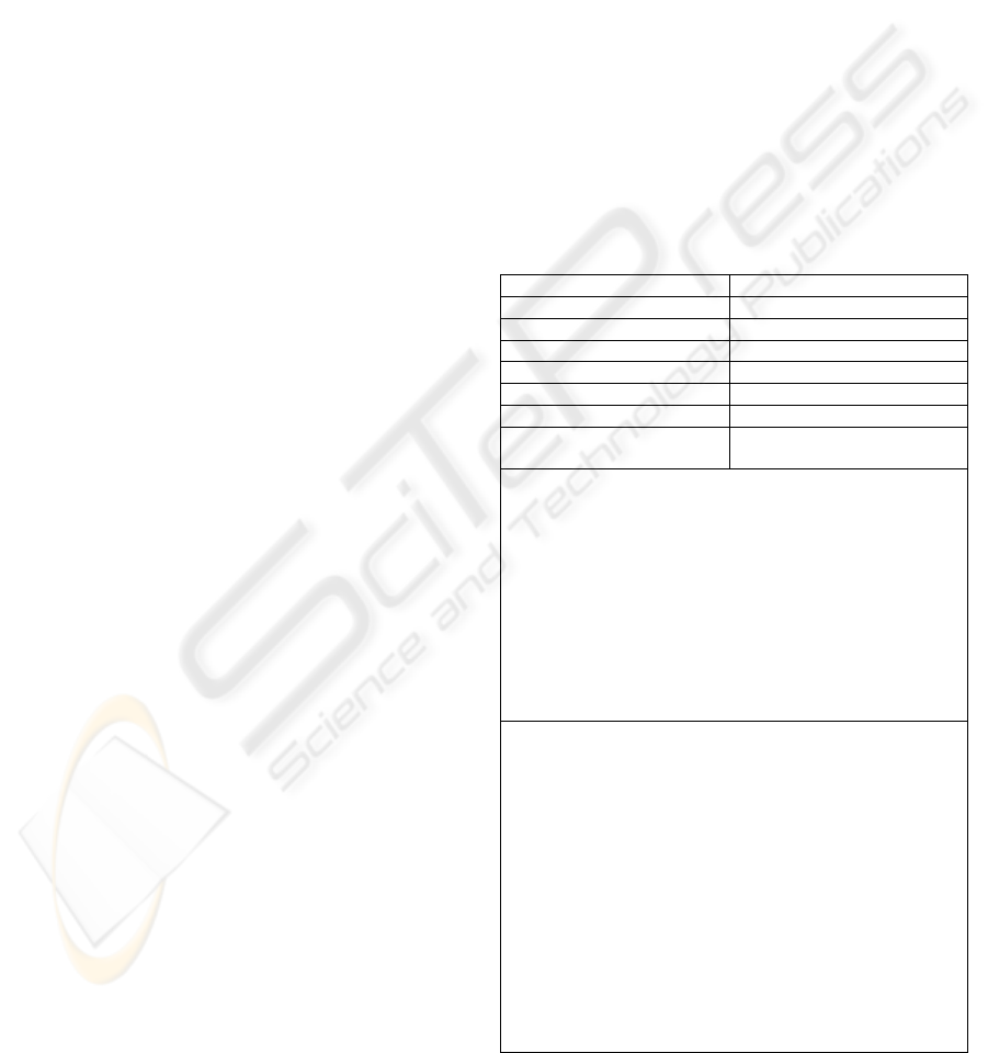
126
Table
1 shows the possible states for the Game
class: each state is defined as a function of the class
attributes. For the sake of space, neither the structure
of the class nor the class diagram appear in this pa-
per; however, expecting that field names are repre-
sentative enough to understand the approach and the
example. Thus:
• Initialized has no variability annotations,
since its description (existence of a board, sufficient
number of clients/players and no assignment of the
turn) is common to all the games.
• Two of the six fields of Playing have vari-
ability annotations (<<optional>> stereotypes and
the names of the products/games affected), since the
game state depends on its possibility of taking
pieces.
• In processing Dices, its two fields have vari-
ability annotations, since they are only applicable to
some products of the line (Ludo and Trivial, which
are the two games using dice).
Table 1: Description of the states for the Game class.
Initia-
lized
this.board != null
this.clients.size() < nPlayers
this.pWithTurn == null
Playing this. clients.size() == nPlayers
this.pWithTurn != null
this.movement == null
this.pieceToMove ==nul
this.positionsToTake==-1 <<optional>> {Chess,
Checkers, Ludo}
this.takenPieces==-1<<optional>> {Chess, Check-
ers, Ludo}
Processin
g Dices
this.followeddSix != -1 <<optional>> {Ludo,
Trivial}
this.pointsInDices !=0 <<optional>> {Ludo, Triv-
ial}
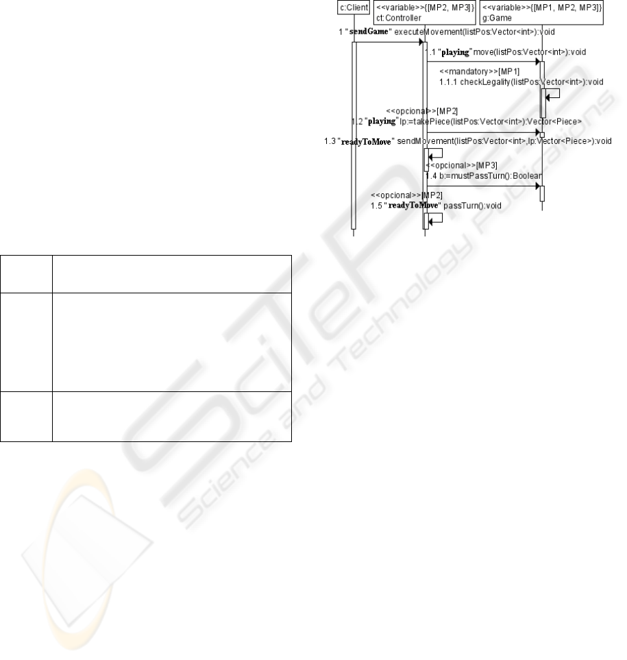
3.2.2 Sequence Diagram Drawing
Annotated sequence diagrams can be drawn once
the states have been described.
Figure 2 shows the sequence diagram for the
normal flow of events of the Piece movement use
case. Besides the stereotypes (which indicate the
variable messages and objects) and the variability
labels (with brackets), the significant messages con-
tain the name of the state that the instance should
reach after executing that message: for example,
after the message executeMovement, the
ct:Controller instance should be in the SendGame
state (note that SendGame does not appear in
Table
1, since it belongs to Controller, not to
Game). In the same way, the expected state of Game
after executing the move message is Playing, which
is described in the previous table.
As it can be seen with this example, it is not dif-
ficult to generate the test scenarios from the dia-
gram, neither adding them the suitable annotations
to include the oracle, which proceed from the ex-
pected states.
Figure 2: Sequence diagram for the normal flow, with
variability and state annotations (highlighted).
4 TRANSFORMATION
ALGORITHMS
The only required products for generating the test
cases are the sequence diagrams, conveniently anno-
tated with the state names (which must have been
previously described, such as in
Table
1). The generation of the test scenarios from
the sequence diagrams is made by means of a set of
transformation algorithms which operate over a set
of metamodels. Thus, a specific metamodel exists
for representing sequence diagrams and another one
for representing states.
4.1 Algebraic Descriptions
Metamodels have been designed to be practical and
formal in the sense given by (Broy, 2001), for whom
Software Engineering needs mathematical descrip-
tions for its modelling aspects, description tech-
niques and development methods, which should not
be too complex. In this context, the OMG standard
metamodels for UML are so complete that its com-
plexity makes hard its processing. Thus, we have
defined a set of metamodels with no incidental de-
tails, and with a solid mathematical basis. The fol-
AUTOMATIC GENERATION OF TEST CASES IN SOFTWARE PRODUCT LINES
127

lowing epigraphs describe an overview of the alge-
braic structure of the metamodels
A Sequence Diagram is composed of life lines
and messages:
SD = (LifeLines, Messages), where:
• l ∈ LifeLines = (Name, Class, In-
puts⊆Messages, Outputs ⊆ Messages, Variation-
Points). VariationsPoints is the set of variation
points in the message, which is explained later .
• m ∈ Messages = (Name, Parameters, Return,
Source⊆LifeLines, Target⊆LifeLines, Variation-
Point, State). This definition contains the description
of one message. As it is seen, it also has a Varia-
tionPoint element (which represents the variability
of the instance) and a State. This one is required for
the further addition of the oracle to test cases.
• v ∈ VariationPoints takes one of the values
in {Optional, Alternative}, if v is Optional, it has a
pair (Label, Conditions), which respectively deter-
mine the VP identifier and the set of applicable con-
ditions; if v is Alternative, the pair (Label, Alterna-
tives) represent the VP identifier and the se of alter-
native functionalities.
A State is composed of a set of conditional sen-
tences, which are written in terms of the class attrib-
utes. Thus:
• State = {ConditionalSentence}.
• c ∈ ConditionalSentence = (Expression, Op-
tionalVariationPoint). Expression is the boolean
expression to be evaluated; Optional represents a
removable condition.
According to (Polo et al., 2007), “a Test Tem-
plate is a sequence of operations of the class under
test with no values that must be later combined with
actual test values to generate test cases”. Sequence
diagrams produce test templates, which can be later
processed to obtain actual test cases. Thus:
• TestTemplate = (Builder, TestValues, Calls,
ObjectUnderTest). Builder represents the instruction
that builds the instance and Calls is the set of in-
structions that execute the operations of the Objec-
tUnder Test, which has a name and a class , with the
TestValues.
• Builder = (BuildOperation, InitValues, Ob-
jectUnderTest)..
• tv ∈ TestValues = (Operation, Argument,
Value). A test value has information about the op-
eration, the argument of the operation where it is
applicable.
• c ∈ Calls = (ObjectUnderTest, Operation,
Oracle, OperationValues, VariationPoint). This
definition contains the description of a call.
• Oracle = (ConditionalSentences, ObjectUn-
derTest). Since the oracle is derived directly from
the States, this definition represents a set of condi-
tional sentences related to an object under test.
4.2 Transformation Algorithms
This section describes how to obtain test cases both
for the line as well as for concrete products. The
section is divided into two parts: the first one shows
how to obtain test templates for the line; the second
shows how to obtain test templates for the products
from the test templates of the line.
4.2.1 Test Templates for the Product Line
The algorithm of Figure 3 takes three arguments: the
sequence diagrams of the line (s), the set of test val-
ues (tvs), and the life line (l) corresponding to the
instance under test. The function returns the test
template for the class under test with the corres-
ponding variability.
The algorithm in
Figure 3 uses two auxiliary
functions: getBuilderOperation returns the instance
of Operation corresponding to the construction of
the object under test (objectUnderTest in
Figure 3);
getOperation, which is called several times in
Figure
3, returns one instance of the Operation correspond-
ing to a message in the source sequence diagram.
getTestTemplate(s:SD, tvs:TestValues, l:LifeLine): Test-
Template {
objectUnderTest = (“obtained”, l.Class)
buildOperation= getBuilderOperation(tvs, l.Class)
initValues = ∅
∀ tv ∈ tvs {
If tv.Operation = buildOperation {
initValues = initValues ∪ {tv} } }
builder = (buildOperation, initValues, objectUnderTest)
result : TestTemplate = (builder, tvs, ∅, objectUnderTest)
∀ m ∈ l.Inputs {
If m ∉ l.Outputs {
operation = getOperation(m, l.Class)
oracle = (m.State.ConditionalSentences, objectUnder-
Test)
operationValues = ∅
∀ tv ∈ tvs {
If tv.operation = operation {
operationalValues = operationalValues ∪ {tv} } }
call = (objectUnderTest, operation, oracle, operationVa-
lues, m.VariationPoint)
result.Calls = result.Calls ∪ { call } } }
getTestCase = result }
Figure 3: Getting test templates from a sequence diagram.
Note that both additional functions suppose the
possibility of accessing the set of constructors and
ICEIS 2009 - International Conference on Enterprise Information Systems
128
methods of the class. In practice, this is feasible us-
ing reflective programming and has been used in
other tools we have developed, such as testooj (Polo
et al., 2007, Polo et al., 2008).
4.2.2 Test Templates for Products
The algorithm shown in Figure 4 returns a test tem-
plate for a specific product from a test template for a
line and the product identifier defined as Value. This
uses the auxiliary function getOracleForProduct
that removes the variability of the general oracle of
the line obtained in the algorithm of the
Figure 3.
When we have an instance of our metamodel
(representing an actual sequence diagram), we can
apply the different functions to obtain the test cases
for the line and for the products. If we have the se-
quence diagram of
Figure 2 and a set of test values,
we will be able to apply the algorithm in
Figure 3 to
obtain general test cases for the line.
Then the algo-
rithm in
Figure 4 produces the concrete test templates
for the games (
Table 2).
getProductTestTemplate(t:TestTemplate, p:Value) :
TestTemplate {
result:TestTemplate = (t.Builder, t.TestValues, ∅,
t.ObjectUnderTest)
//The set of messages is ordered.
//We obtain the first message, after the second
//and finally the last message of the sequence diagram
∀ call ∈ t.Calls {
oracle = getOracleForProduct(call.Oracle, PV)
if call.VariationPoint = λ {
productCall = (call.ObjectUnderTest, call.Operation,
oracle, call.OperationValues, λ)
result.Calls = result.Calls ∪ {productCall}
} else if m.VariationPoint = OptionalVariationPoint{
if ∃ c ∈ OptionalVariationPoint.Conditions
| c.Value = p {
productCall = (call.ObjectUnderTest, call.Operation,
oracle, call.OperationValues, λ)
result.Calls = result.Calls ∪ {productCall}
}
}else if m.VariationPoint = AlternativeVariationPoint {
//Since the alternative variation point implies
//modifications in the implementation of the operation,
//simply we have to add the call without variability.
productCall = (call.ObjectUnderTest, call.Operation,
oracle, call.OperationValues, λ)
result.Calls = result.Calls ∪ {productCall}
} }
getTestCaseProduct = result}
Figure 4: Algorithm for transforming a test template of a
product line into a test template for a product.
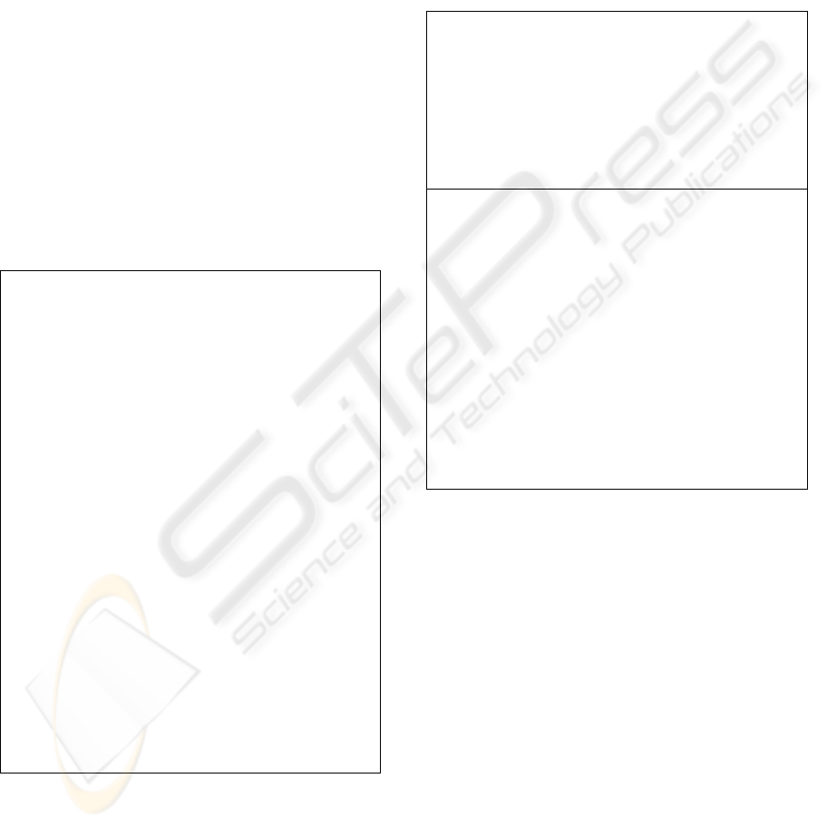
In these concrete cases, the variability (which
was included in the test templates of the line), has
disappeared since it has been applied to the case of
two concrete products. Note that they have some
differences, including the oracle descriptions (com-
partment at the bottom) which proceed from the
adequate selection of the variability labels. Thus,
Trivial does not include any control of the taken
pieces. The last step is transforming the formal
specification of the test cases in executable source
code (
Table 2), which is carried out by a single algo-
rithm.
Table 2: Source code of two product test cases.
public void test1(){
Pos pos1 = new Pos(“1”, “1”);
Pos pos2 = new Pos(“2”, “2”);
Vector<int> arg1 = new Vector();
arg1.add(pos1);
arg1.add(pos2);
Game obtained = new Game();
o.move(arg1);
assertTrue(
o.clients.size() == nPlayers &&
o.pWithTurn != null &&
o.movement == null &&
o.pieceToMove ==null);}
public void test1(){
Pos pos1 = new Pos(“1”, “1”);
Pos pos2 = new Pos(“2”, “2”);
Vector<int> arg1 = new Vector();
arg1.add(pos1);
arg1.add(pos2);
Game o = new Game();
o.move(arg1);
assertTrue(
o.clients.size() == nPlayers &&
o.pWithTurn != null &&
o.movement == null && o.pieceToMove ==null
&&
o.positionsToTake == -1 &&
o.takenPieces == -1);
o.takePiece(arg1);
assertTrue(o.clients.size() == nPlayers &&
o.pWithTurn != null &&
o.movement == null && o.pieceToMove ==null
&&
o.positionsToTake == -1 &&
o.takenPieces == -1);}
5 CONCLUSIONS
This article has presented an approach to generate
test cases in SPL, based on metamodels and trans-
formation algorithms. The main novelty is the pro-
cedure to include oracle instructions in the final test
cases. The approach requires sequence diagrams
which must be annotated with state descriptions. In
this context, the clear and formal specification of the
system is a stronger requirement than in traditional
development. Due to this, the analysis and design
costs are necessarily higher, but they are almost cer-
tainly compensated for during further steps in the
life cycle.
AUTOMATIC GENERATION OF TEST CASES IN SOFTWARE PRODUCT LINES
129

REFERENCES
Baresi, L. and Young, M. (2001) Dept. of Computer and
Information Science, Univ. of Oregon.
Basanieri, F., Bertolino, A. and Marchetti, E. (2002) In
5th Int. Conf. on The Unified Modeling Lan-
guageSpringer-Verlag. LNCS., pp. 383-397.
Bertolino, A. (2007) In Internation Conference on Soft-
ware EngineeringIEEE Computer Society, pp. 85-103.
Bertolino, A., Gnesi, S. and di Pisa, A. (2004) PLUTO: A
Test Methodology for Product Families, Software
Product-family Engineering: 5th Int.l Workshop, PFE
2003, Siena, Italy, November 4-6, 2003.
Broy, M. (2001) Towards a Mathematical Foundation of
Software Engineering Methods, IEEE Transactions on
Software Engineering, 27, 42-57.
Clements, P. and Northrop, L. (2002) Software Product
Lines: Practices and Patterns, Addison-Wesley,.
Harrold, M. J. (2000) Testing: a Roadmap. In Int. Conf. on
Soft. Eng. ACM, Limerick, Ireland, pp. 61-72.
McGregor, J., Northrop, L., Jarrad, S. and Pohl, K. (2002)
Initiating Software Product Lines., IEEE Software.
Nebut, C., Pickin, S., Le Traon, Y. and Jezequel, J. (2003)
Automated requirements-based generation of test
cases for product families, Automated Software Engi-
neering, 2003. Proceedings. 18th IEEE International
Conference on, 263-266.
Offutt, A. J., Liu, S., Abdurazik, A. and Amman, P.
(2003) Generating test data from state-based specifica-
tions, Software Testing, Verification and Reliability,
25-53.
Olimpiew, E. and Gomaa, H. (2006) Customizable Re-
quirements-based Test Models for Software Product
Lines, Int. Workshop on Soft Product Line Testing.
Polo, M., Piattini, M. and García-Rodríguez, I. (2008)
Decreasing the cost of mutation testing with second-
order mutants, Soft. Testing, Verification and Reliabil-
ity.
Polo, M., Piattini, M. and Tendero, S. (2007) Integrating
techniques and tools for testing automation, Soft. Test-
ing, Verification and Reliability, 17, 3-39.
ICEIS 2009 - International Conference on Enterprise Information Systems
130
