
INNOVATIVE PROCESS EXECUTION IN SERVICE-ORIENTED
ENVIRONMENTS
Dirk Habich, Steffen Preissler, Hannes Voigt and Wolfgang Lehner
Dresden University of Technology, Database Technology Group, 01069 Dresden, Germany
Keywords:
Information systems, Service-oriented architecture, Database technologies.
Abstract:
Today’s information systems are often built on the foundation of service-oriented environments. Although the
fundamental purpose of an information system is the processing of data and information, the service-oriented
architecture (SOA) does not treat data as a core first class citizen. Current SOA technologies support neither
the explicit modeling of data flows in common business process modeling languages (such as BPMN) nor the
usage of specialized data transformation and propagation technologies (for instance ETL-tools) on the process
execution layer (BPEL). In this paper, we introduce our data-aware approach on the execution perspective as
well as on the modeling perspective of business processes.
1 INTRODUCTION
Fundamentally, information systems refer to systems
of persons, data or information elements and activities
processing the data and information in an organiza-
tion. Computer-oriented information systems are the
field of study for information technologies. The im-
plementation of information technologies to support
business processes that cover all present and prospec-
tive system requirements for an end-to-end scenario is
still one of the most challenging issues. A recent ap-
proach within this field is the service-oriented archi-
tecture (SOA) (Erl, 2005). The major characteristic of
SOA is the unification of business processes by struc-
turing large applications as an collection of smaller
and independent modules called services (Erl, 2004).
Web services (Erl, 2005) are the de-facto stan-
dard for implementing service-oriented components.
To orchestrate these services to business processes
that achieve higher level functionality, the workflow
language WSBPEL (OASIS, 2007) (BPEL for short)
provides specific functional-oriented elements, like
invoke, switch or sequence to describe the functional
process flow. However, this specification type con-
siders technical details in order to model executable
business processes. Therefore, modeling an efficient
BPEL process requires in-depth technical knowledge
of the Web service domain and its protocols.
Aside from the general flexibility of orchestrated
services, the XML-based SOAP message exchange
between service and process inherits the already well-
investigated CPU and memory usage bottleneck when
processing XML-formatted data with other program-
ming language paradigms (Chen et al., 2006; Chiu
et al., 2002; Habich et al., 2007a). These problems
become more evident if large amounts of data or in-
formation have to be exchanged between services in
a business process. This is a fundamental shortcom-
ing of the Web service approach because data or in-
formation elements are not first class citizens. How-
ever, data and information elements are fundamental
aspects of information systems as described above.
To treat data as a first class citizen, two major as-
pects have to be considered. The first aspect is the
explicit handling of data within the process descrip-
tion at design time. This implies the explicit modeling
of data flows between services as well as the explicit
specification of data transformation rules between the
different data structures of these services. The second
aspect is the integration of specialized data transfer
mechanisms that use the information of these mod-
eled data flows to transform and propagate data be-
tween its services in an efficient way.
To integrate these aspects into SOA, several mod-
ifications on the Web service as well as the process
description level have to be done. On the Web ser-
vice level, we already proposed the concept of data-
grey-box Web services (Habich et al., 2007a). Using
this extension, the data aspect is a first class citizen
represented by (i) an extended Web service descrip-
tion and (ii) an enhanced service invocation proce-
dure. In this case, massive data is transferred between
299
Habich D., Preissler S., Voigt H. and Lehner W. (2009).
INNOVATIVE PROCESS EXECUTION IN SERVICE-ORIENTED ENVIRONMENTS.
In Proceedings of the 11th International Conference on Enterprise Information Systems - Databases and Information Systems Integration, pages
299-302
DOI: 10.5220/0002004402990302
Copyright
c
SciTePress
services and clients by specialized transfer mecha-
nism. One the process description level, we already
introduced BPEL data transition as extension (Habich
et al., 2007b) for BPEL. However, since BPEL al-
ready requires in-depth technical knowledge of Web
services and its protocols, extending it with an addi-
tional data aspect could become much too complex
to model for a business process designer, who basi-
cally has in-depth knowledge of workflow semantic
on business level (Habich et al., 2007b). Therefore,
we have to consider a more abstract process notation
for business processes. The Business Process Mod-
eling Notation (BPMN) (OMG, 2008) is emerging to
take this role within the development cycle of busi-
ness processes.
In this paper, we focus on abstract process mod-
eling supporting the definition of explicit data flows.
We define rules to support the derivation from data-
aware BPMN notation to valid data-aware BPEL pro-
cesses descriptions (Section 2). Since the data flow
is orthogonal to the control flow, schema transforma-
tions of data between different services have to be
modeled as well. In Section 3, we consider those data
schema transformations and its execution at runtime.
We give an overview of our approach to automati-
cally generate data schema transformation implemen-
tations for different transfer mechanisms. Finally, we
conclude this paper in Section 4.
To illustrate our developed approach, we use the
depicted abstract process from Figure 1 as running
example throughout the paper. The illustrated process
generates a report for a large data set of sensor data,
whereas three successive tasks constitute the process.
The first task (Get Sensor Data) retrieves the data
set for a requested range of time and provides this
data set and the number of records it contains for the
subsequent tasks. The second task (Select Report
Layout) chooses several appropriate layout parame-
ters for the report based on the number of retrieved
records and hands them to third task. Finally, the
third task (Generate Report) generates the report
for the data set according to the chosen parameters.
The dashed line connecting the first and the third task
indicates an explicit data flow between these two tasks
meaning a data exchange between these two tasks.
Get Sensor Data
Select Report
Layout
Generate Report
Figure 1: Sample scenario for report generation in ab-
stract notation.
2 BPMN MODELING AND
DERIVATION
The starting point of our data-aware process modeling
and its execution is our developed data-grey-box Web
service technology (Habich et al., 2007a). Modeling
a data-aware BPEL process with its extended execu-
tion semantic requires in-depth technical knowledge
of Web service technology in general and our data-
grey-box service in specific as presented in (Habich
et al., 2007b). From our point of view, this is too
complex for process designers, who want to focus
on the business semantic. To provide a more conve-
nient modeling notation that abstracts from the tech-
nical process execution layer, we utilize the Business
Process Modeling Notation (OMG, 2008) (BPMN for
short). In this section, we describe how we extend
BPMN to explicitly express the data aspects of the
business process. Furthermore, we present rules to
derive an efficient executable BPEL process descrip-
tion from a modeled BPMN process.
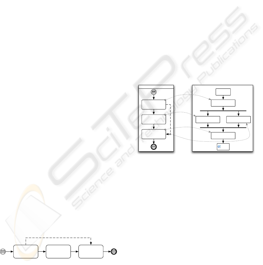
Get Sensor Data
Select Report
Layout
Generate Report
invoke
DM-Service
Select
Report Layout
Get
Sensor Data
Generate
Report
receive
reply
BPMN process BPEL process
Organization1
Figure 2: BPMN to BPEL derivation of sample sce-
nario
The left side notation in Figure 2 depicts a BPMN
notation style process and represents our running pro-
cess example from Figure 1. The core notation ele-
ment in BPMN is a task (e.g. Get Sensor Data). A
task represents an activity that is executed in a single
step. In general, tasks can also represent nested sub
processes, but for our scenario we consider them to
be atomic. To specify the sequence, in which tasks
are executed, a sequence flow is placed between two
tasks. The direction of sequence flow indicates the
control flow dependency between both tasks. Ad-
ditionally, sequence flows can only be placed be-
tween activities that belong to the same organization
or stakeholder. If the control flow depends on an
information exchange between two organizations, a
message flow is used instead of a sequence flow to
indicate this information exchange. To get a better
visual overview, organizations are represented by dif-
ICEIS 2009 - International Conference on Enterprise Information Systems
300

ferent pool elements that enclose all tasks of one or-
ganization and the sequence flows linking these tasks.
This implies that message flows are only drawn be-
tween different pools. Pools can be further structured
with lanes dividing an organization into different de-
partments. Our sample process (Figure 1) shows one
pool, and hence one organization, where all three
tasks are connected using sequence flows. Moreover,
BPMN provides a data object element, which can be
linked to tasks with directed or undirected associa-
tions. It does not have any direct affect on sequence
flows or message flows and only adds further informa-
tion to the model.
Since the data object and its association edges
does not provide any additional benefit to the con-
trol flow, they could be used to model data-flows
in BPMN. However, to maintain compatibility with
other existing BPMN process descriptions, we leave
the semantics of the association edge and the data
object untouched. Instead, we introduce a new ex-
plicit data edge to express an explicit data flow. The
data edge indicates that the connected tasks exchange
data. A data edge can connect two tasks within one
pool (one organization) as well as two tasks in differ-
ent pools (different organizations). An organization-
internal data edge is depicted in Figure 2 between the
tasks Get Sensor Data and Generate Report.
After specifying the modeling constructs to model
an explicit data aspect in BPMN, we now define
derivation rules to map a data-aware BPMN diagram
to a valid data-aware BPEL description. BPMN is an
abstract notation and hides all technical details neces-
sary for an implementation of the modeled process. A
transformation from data-aware BPMN to data-aware
BPEL can, therefore, construct only a non-executable
skeleton of the process in BPEL notation. How-
ever, this skeleton contains (i) the control flow struc-
ture as well as (ii) data management information in-
cluding standard service calls implementing the data
flow. Instead of using our proposed BPEL data transi-
tion (Habich et al., 2007b), we are now able to utilize
standard BPEL constructs resulting in high compat-
ibility with various existing BPEL implementations.
In case, the BPEL data transitions are realized by in-
tegrating additional specialized service calls for the
data management.
In detail, the BPMN-to-BPEL transformation gen-
erates service invocation activities for all tasks and
connects them together according the control flow
specified in BPMN. Every data edge in BPMN is
mapped to a flow environment between two invoke ac-
tivities in BPEL that represents the source task and
the target task of the data flow. Within this flow en-
vironment, two parallel control flow paths are gen-
erated. The first path represents the normal control
flow between the source and target task in BPMN.
The second path invokes the data flow specific Data
Mapping Service (DM-Service). This DM-Service is
responsible for the adaptation of the data structures
between the source and target services using special-
ized tools like an ETL-tool. Because of this parallel
execution of control and data flow, the data mapping
does not slow down intermediate traditional service
invocations. The merge of the control flow at the end
of the flow environment ensures that the succeeding
task is only executed, if both paths are successfully
processed.
Figure 2 illustrates this BPMN-to-BPEL transfor-
mation for our running example. Here, the transfor-
mation maps the source task (Get Sensor Data) and
the target task (Generate Report) to two appropri-
ate invoke activities. Both invoke activities represent
a data-grey-box Web services call, so the transfor-
mation also realizes the data reference flow between
the two services by suitable assignments of the neces-
sary service invocation parameters. Furthermore, the
transformation generates a flow environment between
those two invoke activities. In our example, the first
(left) path of the flow environment contains the invoke
activity Select Report Layout, which represents
the BPMN task of the same name. In the second path
the transformation generates the DM-Service invoca-
tion. The DM-Service executes the data transforma-
tion between the data structures of the Get Sensor
Data service and the Generate Report services.
To turn the process skeleton into an executable
BPEL process, the process designer has to select ap-
propriate services for all invoke activities. This step
provides the concrete schemas of the input and out-
put data of each service. The next step is to define
the mapping rules which are used by the DM-Service.
This part is covered by the following section. After
this enrichment of the BPEL skeleton, the BPEL pro-
cess is executable in an efficient way.
To conclude this section, the major advantages of
this approach are (1) a convenient process modeling
approach without too many technical details, (2) the
transformation of a BPMN process with explicit data
flows into a data-aware, but standard compliant BPEL
process and (3) an efficient process execution.
3 DATA MAPPINGS
The last step to realize our data-aware process exe-
cution consists of the specification of data mappings
between services participating in a data flow. In gen-
eral, each available and data-specific tool can be used
INNOVATIVE PROCESS EXECUTION IN SERVICE-ORIENTED ENVIRONMENTS
301

to map output data from a source service to input data
of the target service. However, this would restrict the
flexibility of our approach. Therefore, we focus on a
more abstract way.
<<DPD>>
EAI
<<DPD>>
EAI
<<DPD>>
ETL
<<DPD>>
ETL
<<DPD>>
FDBMS
<<DPD>>
FDBMS
<<PIM>>
UML
<<PIM>>
BPMN
<<A-PSM>>
MTM
import import exportexport
<<PSM>>
ETL
<<DPD>>
ETL
generate
PSM
generate
DPD
analyze and optimize
A-PSM
<<PSM>>
EAI
<<DPD>>
EAI
<<PSM>>
FDBMS
<<DPD>>
FDBMS
generate
DPD
generate
DPD
generate
PSM
generate
PSM
Figure 3: Main Data Integration Modeling and Gen-
eration Approach.
Generally, data mapping is a fundamental aspect
within data integration processes (Dessloch et al.,
2008). In (B
¨
ohm et al., 2008), we proposed an model-
driven approach for integration processes. The overall
approach is shown in Figure 3. Integration processes
are modeled in a platform-independent way (PIM)
using e.g. BPMN or BPEL and several platform-
specific (PSM) integration tasks are generated auto-
matically. During this generation, several optimiza-
tion techniques can be applied (B
¨
ohm et al., 2008) to
derive optimized data integration tasks.
We apply this approach to our current setting to
specify the mapping of data flows. In this case, not
only data mappings, but also enhanced data manipu-
lation operations can be modeled in an abstract and
platform-independent way. From this model, we are
able to derive optimized mapping tasks for several
data specific data mapping tools. These mapping
tasks are used within the DM-Services. The advan-
tage of this procedure is (1) a high flexibility regard-
ing the DM-Services and (2) the push-down of data
relevant tasks to the DM-Services. In this way, we
have decoupled the functional orchestration of ser-
vices from the data mapping specification between
services in a process. Both aspects are modeled using
an abstract BPMN approach and optimized technical
realizations are derived in a combined fashion.
4 CONCLUSIONS
In this paper, we have presented our developed inno-
vative approach of executing business processes by
considering the data aspect explicitly during model-
ing time and during runtime. In detail, we have pro-
posed an abstract process modeling supporting the
definition of explicit data flows. The specification
of these data flows are also done in an abstract way.
Form both abstract models, we derive optimized tech-
nical realizations in a combined fashion. To summa-
rize, the result of our work is that data is a first class
citizen within SOA meaning on the modeling as well
as on the execution level.
ACKNOWLEDGEMENTS
The project was funded by means of the German Fed-
eral Ministry of Economy and Technology under the
promotional reference ”’01MQ07012”’. The authors
take the responsibility for the contents.
REFERENCES
B
¨
ohm, M., Wloka, U., Habich, D., and Lehner, W. (2008).
Model-driven generation and optimization of complex
integration processes. In Proc. of ICEIS, pages 131–
136.
Chen, S., Yan, B., Zic, J., Liu, R., and Ng, A. (2006). Eval-
uation and modeling of web services performance. In
Proc. of ICWS, pages 437–444.
Chiu, K., Govindaraju, M., and Bramley, R. (2002). Inves-
tigating the limits of soap performance for scientific
computing. In Proc. of HPDC, pages 246–254.
Dessloch, S., Hern
´
andez, M. A., Wisnesky, R., Radwan, A.,
and Zhou, J. (2008). Orchid: Integrating schema map-
ping and etl. In Proc. of ICDE, pages 1307–1316.
Erl, T. (2004). Service-oriented Architecture. A Field Guide
to Integrating XML and Web Services. Prentice Hall
PTR.
Erl, T. (2005). Service-Oriented Architecture (SOA): Con-
cepts, Technology, and Design. Prentice Hall PTR.
Habich, D., Preissler, S., Lehner, W., Richly, S., Aßmann,
U., Grasselt, M., and Maier, A. (2007a). Data-grey-
box web services in data-centric environments. In
Proc. of ICWS, pages 976–983.
Habich, D., Richly, S., Grasselt, M., Preissler, S., Lehner,
W., and Maier, A. (2007b). Bpel-dt - data-aware ex-
tension of bpel to support data-intensive service appli-
cations. In Proc. of WEWST.
OASIS (2007). Web services business process execu-
tion language 2.0 (ws-bpel). http://www.oasis-
open.org/committees/tc
h
ome. php?wg
a
bbrev =
wsbpel.
OMG (2008). Business process modeling notation.
http://www.bpmn.org/.
ICEIS 2009 - International Conference on Enterprise Information Systems
302
