
INTEGRATING VR IN AN ENGINEERING COLLABORATIVE
PROBLEM SOLVING ENVIRONMENT
Ismael H. F. dos Santos
Petrobras Research Center, Ilha do Fundão, Rio de Janeiro, Brazil
Alberto Raposo, Marcelo Gattass
Department of Informatics, PUC-Rio, Rio de Janeiro, Brazil
Keywords: Collaborative problem solving environments, Scientific workflow management system, Virtual
environments.
Abstract: We present an environment for executing engineering simulations and visualizing results in a Virtual
Environment. The work is motivated by the necessity of finding effective solutions for collaboration of team
workers during the execution of complex Petroleum Engineering projects. By means of a Scientific
Workflow Management System users are able to orchestrate the execution of different simulations as
workflow tasks that can be arranged in many ways according to project requirements. Within a workflow, as
its last step, the most interesting cases can be selected for visualization in a distributed collaborative session.
1 INTRODUCTION
The present work is motivated by the necessity of
finding effective solutions for collaboration of team
workers during the execution of large and complex
Petroleum Engineering (PE) projects. Those projects
usually require the execution of a large number of
engineering simulations, encapsulated as
engineering services, combined in different orders
and rearranged in different subsets according to each
project requirement. By means of a Scientific
Workflow Management System users are able to
orchestrate the execution of engineering simulations
as workflow tasks that can be arranged in many
different ways. Within a workflow, as its last step,
the most interesting cases can also be selected for
visualization in an immersive distributed
collaborative session.
A Problem Solving Environment (PSE) is a
specialized software system that provides all the
computational facilities needed to solve a target
class of problems. These features include advanced
solution methods, automatic and semiautomatic
selection of solution methods, and ways to easily
incorporate novel solution methods. Moreover, PSEs
use the language of the target class of problems, so
users can run them without specialized knowledge of
the underlying computer hardware and software
technology (Houstis et al., 1997).
In this work, the presented solution, called
Collaborative Engineering Environment (CEE) is
intended to create a useful collaborative PSE
through the composition of different tools for
distributed group work:
1. Virtual Reality Visualization tool (VRV) –
EnViron, a custom VRV adapted for collaborative
visualization of PE simulations in an immersive or
desktop Virtual Environment;
2. Scientific Workflow Management System
(ScWfMS) – an open-source BPEL-workflow
implementation used as a process-oriented tool to
control the execution of PE projects;
3. Videoconference System (VCS) –
CSVTool, a custom VCS developed for supporting
human communication, providing integrated audio
and video channels, subject to defined control
policies;
In the following sections we present some
aspects of the developed CEE. In section 2 we
present the main characteristics of PE projects
discussing some problems addressed by CEE.
Related works that inspired the development of the
CEE are presented in section 3. In section 4, we
describe the CEE architecture. A case study is
presented in section 5 and conclusions in section 6
finish the paper.
124
dos Santos I., Raposo A. and Gattass M. (2009).
INTEGRATING VR IN AN ENGINEERING COLLABORATIVE PROBLEM SOLVING ENVIRONMENT.
In Proceedings of the 11th International Conference on Enterprise Information Systems - Human-Computer Interaction, pages 124-129
DOI: 10.5220/0002012501240129
Copyright
c
SciTePress

2 PETROLEUM ENGINEERING
PROJECTS
Usually PE projects involve not only geographically
distributed teams but also teams of specialists in
different areas using different software tools, both
commercial and homemade. The interoperability of
those tools is still an issue in the industry and is a
mandatory requisite for any viable collaborative
solution.
Due to their huge complexity, PE projects are
divided into smaller interrelated subprojects where
each one deals with an abstract representation of the
others. Because decisions are interdependent the
necessity for collaboration is a key issue in this area.
Each team activity or new decision can affect other
activities. For example, during the design of a
floating production unit (FPSO - floating production
storage and offloading) changing the position of
large and heavy equipment in the process plant can
compromise the stability of the production unit. In
some cases there is also an intrinsic coupling among
the solutions of the different subprojects, which
requires a lot of interactions and discussions among
the teams involved. This is the case of the mooring
system and of the production risers’ subsystems. On
one hand if the mooring system allows great
fluctuations of the production unit, it can simply
damage the production risers; on the other hand the
presence of the risers itself helps to weaken the
movements of the production unit which contributes
positively to the equilibrium of the system. In order
to achieve collaboration and interoperability
between those subprojects a software-based interface
is required.
Another challenge present in PE projects is
related to the visualization of large engineering
simulations. During the conceptual design phase of
an industrial plant, several simulations should be
applied to assess the robustness and feasibility of the
project. Some of these simulations may require huge
computational efforts to be processed, even for
powerful computer clusters. Visualization should be
as precise as possible in order to provide the user a
full understanding of the results of the simulation.
In principle, PSEs can solve simple or complex
problems, support both rapid prototyping and
detailed analysis, and can be used both in
introductory education and at the frontiers of science
and engineering. For PE projects a PSE should focus
on the development and integration of scientific
tools and technologies coupled with collaborative
environments to support the modeling and
simulation of complex scientific and engineering
problems constituting a useful CPSE (Collaborative
Problem Solving Environment). These capabilities
enable engineers to easily setup computations in an
integrated environment that supports the storage,
retrieval, and analysis of the rapidly growing
volumes of data produced by computational studies.
In conclusion, according to the above challenges
presented for PE projects, the proposed CEE is
conceived as a useful CPSE for better controlling
and executing specialized engineering projects
through the use of its collaboration and visualization
capabilities.
3 RELATED WORK
Problem Solving Environments have been built for a
number of scientific domains. For example, (Parker
et al., 1998) describe SCIRun, a PSE that allows
users to interactively compose, execute, and control
a large-scale computer simulation by visually
“steering" a dataflow network model. SCIRun
supports parallel computing and output
visualization, but originally has no mechanisms for
experiment managing and archiving, optimization,
real-time collaboration, or modifying the simulation
models themselves.
Vistrails (Callahan et al., 2006) is a visualization
management system that provides a Scientific
Workflow infrastructure which can be combined
with existing visualization systems and libraries. A
key feature that sets Vistrails apart from previous
Visualization Systems as well as Scientific
Workflow Systems is the support for data
exploration. It separates the notion of dataflow
specification from its instances. A dataflow instance
consists of a sequence of operations used to generate
a specific visualization. Vistrails approach inspired
our CEE strategy but some of the differences of the
CEE are the use of a BPEL (Business Process
Execution Language) ScWfMS and the focus on
immersive and realistic visualization.
In the Geology field, (Kreylos et al., 2006)
presented an approach for turning immersive
visualization software into a scientific tool. They
created immersive visualization software, with
measurement and analysis tools that allow scientists
to use their real-word skills and methods inside a
VE. They emphasized that VR visualization alone is
not sufficient to enable an effective work
environment. This observation has also motivated us
to create some additional tools for our VR
visualization subsystem of the CEE.
The effective integration of “smart” graphical
INTEGRATING VR IN AN ENGINEERING COLLABORATIVE PROBLEM SOLVING ENVIRONMENT
125

user interfaces, with some advisory support,
Scientific Visualization, VR techniques, Engineering
Analysis and Modeling Tools aid in the automation
of modeling analysis and data management for large
and complex PE projects. To enhance engineers
ability to share information and resources with
colleagues at remote locations, collaborative and
real-time technologies integrated into a CPSE
provide a unified approach to the scientific and
engineering discovery and analysis process.
A combination of a CPSE and VR visualization,
which is not addressed by the aforementioned
visualization systems, constitutes a strategic enabler
for a successful data exploration and knowledge
dissemination among workers in engineering
enterprises. VR visualization technologies enhance
the content knowledge within the engineering
disciplines. In conjunction with collaboration both
provide valuable insights for better Decision Support
with risk mitigation. (Dodd, 2004) has mentioned
that the next big management push is the
empowerment of interdisciplinary teams with
collaboration tools that include remote and
immersive visualization on the desktop. Sharing the
same opinion as Dodd we emphasize that the
combination of collaborative tools and VR
visualization constitutes a powerful component to
our CEE architecture.
4 CEE MODEL
The developed CEE, as a specialized CPSE, allows
users to collaboratively solve their problems through
the use of predefined workflows or assembling new
ones. Each workflow comprises a sequence of
simulations that usually ends with a collaborative
visualization session supported by the VR
Visualization tool. Based on a thoroughly analysis of
the domain of PE projects used as our prototype
scenario, we defined a set of collaborative and
visualization features for dealing with the difficulties
described above. In what follows we present the
major CEE functionalities towards this direction.
4.1 Collaborative Work
The support for collaborative work is provided by
the use of a Scientific Workflow Management
System (ScWfMS), Videoconference System and a
collaborative support for creating annotations about
the engineering artifacts used in the projects.
An annotation, in our context, is any textual
information that users want to add to their projects to
enrich the content or just for documentation; it can
have a private or public (shared) scope. Annotations
can be associated to any engineering artifact
manipulated in a PE during a collaborative
visualization session that usually happens at the end
of execution of any sequence of engineering
simulations, as the last step of typical engineering
workflow. It could, for example, be a kind of
instructional information denoting a sequence of
operations that should be undertaken during a
maintenance intervention in a production unit, or
some information used to highlight interesting or
anomalous events observed on the results of the
simulations.
4.2 CEE Videoconference System
Audio and video communications are fundamental
components of collaborative systems (Isaacs and
Tang, 1994). Audio is an essential channel for
supporting synchronous work, and video is
important to provide a sense of co-presence
facilitating negotiation tasks.
Videoconferencing Systems contain no
knowledge of the work processes, and therefore are
not “organizationally aware”. These systems are best
suited for unstructured group activities once that
audiovisual connectivity and shared documents
enable flexible group processes. The drawback is
that coordination tasks are left to the conference
participants.
We have developed a multiplatform
videoconferencing tool, CSVTool (Pozzer et al.,
2003). The use of a custom tool allows a tight
integration of this service into the CEE, with no
duplication of session-management functionalities,
and the direct control of audio and video streams
according to the coordination policies defined.
4.3 CEE Visualization Tool
EnViron (ENvironment for VIRtual Objects
Navigation) (Raposo et al., 2006) is a tool developed
to facilitate the use of CAD models in VR
applications. It is a system composed of a 3D
environment for real time model visualization, and
exportation plugins, which import model data from
other applications, allowing EnViron to visualize
and interact with different kinds of 3D data.
The applicability of VR techniques for 3D
geometric CAD models has been restricted to design
review, virtual prototyping and marketing purposes,
mainly in the automotive and aircraft industries.
More recently, 3D CAD models are starting to show
ICEIS 2009 - International Conference on Enterprise Information Systems
126

their potential in VR applications for diverse
purposes, such as ergonomic studies, safety training
for Health, Safety Environments (HSE), and
visualization of physical simulations, project
documentation and real-time operational data.
EnViron is integrated into CEE offering
resources for real-time 3D visualization and
interaction in CAD models with enough realism and
performance to be used for collaborative virtual
prototyping, design review, change management
systems, training, and visualization of engineering
simulations among other activities.
4.4 CEE Scientific Workflow
In recent years, several industries have improved
their operations through Workflow Management
Systems (WfMS) – improvement of data
management and better coordination of activities
through specific Business and Scientific and
Engineering Process. However, there are remarkable
differences between Business (BWfMS) and
Scientific Workflows (ScWfMS). (Weske et al.,
1998) identified that in a scientific environment
scientists will typically specify their workflows
themselves, while in a business environment; a
system administrator is commonly responsible for
this task. Another characteristic of ScWfMS pointed
in their work is the need to trace workflow
executions. An engineer may need to reuse a
workflow in order to reproduce results. The
operations a user performs on a given data must be
recorded in order to provide engineers with the
benefits of successful and unsuccessful workflows.
Scientific workflows often begin as research
workflows and end up as production workflows.
Early in the lifecycle, they require considerable
human intervention and collaboration; later they
begin to be executed increasingly automatically.
Thus in the production mode, there is typically less
room for collaboration at the scientific level and the
computations are more long-lived. During the
research phase, scientific workflows need to be
enacted and animated (fake enactment) far more
intensively than business workflows. In this phase,
which is more extensive than the corresponding
phase for business workflows, the emphasis is on
execution with a view to design, and thus naturally
includes iterative execution. The corresponding
activity can be viewed as a “Business Process
Engineering” (BPE). For this reason, the approaches
for constructing, managing, and coordinating
process models are useful also in scientific settings.
In this way, Scientific Workflows are to PSEs what
Business Workflows are to Enterprise Integration.
4.5 CEE Implementation
Service-Oriented Architecture (SOA) is a style of
architecting software systems by packaging
functionalities as services that can be invoked by
any service requester (Ort, 2005). An SOA typically
implies a loose coupling between modules.
Wrapping a well-defined service invocation
interface around a functional module hides details of
the module implementation from other service
requesters. This enables software reuse and also
means that changes to a module’s implementation
are localized and do not affect other modules as long
as the service interface is unchanged.
The adoption of an SOA for CEE produced a
reduction of technology development costs by
leveraging functions already built into legacy
systems. SOA architectures are becoming a popular
and useful means of leveraging internet technologies
to improve business processes in the oil & gas
industry nowadays.
An Enterprise Service Bus (ESB) is a pattern of
middleware that unifies and connects services,
applications and resources within an enterprise. ESB
is a platform built on the principles of SOA and
other open standards to help applications integrate
seamlessly. Put another way, it is the framework
within which the capabilities of a business'
application are made available for reuse by other
applications throughout the organization and
beyond. The ESB is not a new software product, it's
just a new way of looking at how to integrate
applications, coordinate distributed resources and
manipulate information. Unlike previous approaches
for connecting distributed applications, such as RPC
or distributed objects, the ESB pattern enables the
connection of software running in parallel on
different platforms, written in different languages
and using different programming models.
Our proposed CEE has component-based
architecture in order to facilitate the reuse of
elements. The architecture of the CEE uses a BPEL
ScWfMS as its kernel while the CSVTool, Environ
and the other components are seamlessly accessed
through the ESB according to the collaborative
necessities of the teamworkers.
When the service-oriented approach is adopted
for designing the CEE, every component, regardless
of its functionality, resource requirements, language
of implementation, etc., provides a well-defined
service interface that can be used by any other
component in the environment. The service
INTEGRATING VR IN AN ENGINEERING COLLABORATIVE PROBLEM SOLVING ENVIRONMENT
127
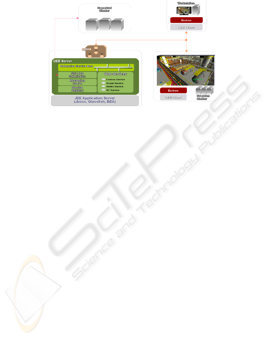
Figure 1: CEE architecture.
abstraction provides a uniform way to mask a
variety of underlying data sources (real-time
production data, historical data, model parameters,
reports, etc.) and functionalities (simulators,
optimizers, sensors, actuators, etc.). A Workflow,
actually, in our context, a Scientific Workflow, is
composed by coupling service interfaces in the
desired order. These workflows specifications are
created through a graphical front end, workflow
designer, and the actual service calls are generated
automatically and have their execution controlled by
the workflow engine.
CEE has a client server architecture, where the
CEE-server is deployed in a JEE (Java Enterprise
Edition) Application Server (AppServer) which
allows better scalability and automatic transaction
control. The CEE principal services resides in the
AppServer where a Service Registry is used to
record all available services existent in the CEE-
clients, for example the CEE-VRV tool, Environ,
should be available on a CEE-client machine for
allowing the user to participate in an Environ
Collaborative Session, controlled by the CEE
Service Coordinator (Figure 1).
The Environ Collaborative Session is
implemented with the help of a Java Messaging
Service (JMS) infrastructure available in the
AppServer, providing a communication channel
between peers participating in the Session. The
channels are implemented as JMS topics (global
channels) and queues, individual channels for each
CEE-client (Figure 2). The Environ collaboration
session is controlled by the CEE service coordinator
and by each EvironProxy started on demand on a
CEE-client machine by the Environ Service, which
is a service demo registered at the Service Registry
in CEE-server signaling the availability of Environ
in the CEE-client.
5 DESIGN REVIEW WORKFLOW
Design review is the process of checking the
correctness and consistency of an engineering
project, and making the necessary corrections to it.
CEE is very helpful in this process, for instance to
assess the safeness of different emergency escape
pathways in case of an emergency in the plant.
The Design Review workflow is a very
simplified version of the previously workflow,
where BPEL engine reads user input parameters and
invokes CEE Service Coordinator to create an
Environ Collaborative Session for users to
collaborate, manipulating engineering artifacts and
creating annotations in the model accordingly.
Object manipulation is an important resource in
design review. The ability of moving, rotating and
scaling objects is important for various purposes
such as joining different models in a scene, viewing
hidden portions of the model, planning the
placement of a new piece of equipment on a plant,
and simulating a maintenance or intervention
operation in a process plant are also valuable tools.
As an example, the maintenance plan can be
enriched with a detailed sequence of operations with
annotations carefully chosen to be presented as an
animation for the maintenance engineers during the
operation (Figure 3). Moreover, integration with a
database is useful to allow the user to create
annotations on the model emphasizing critical parts.
It is also possible to show comments attached to
ICEIS 2009 - International Conference on Enterprise Information Systems
128
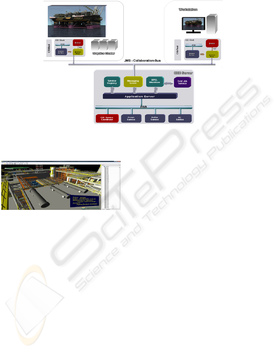
Figure 2: CEE JMS messaging architecture.
objects, which can be used, for example, as
recommendations for project management.
Figure 3: Maintenance plan with annotations.
6 CONCLUSIONS
This paper presented an SOA of the CEE that we
have developed. CEE is still in its infancy but is
proving to be an effective Collaborative Problem
Solving environment, allowing users to mitigate
their problems during the execution of large and
complex PE projects. Currently we are building
more tools to improve the effectiveness of the use of
VR technology by the team workers. Although this
work is focused on a solution for Petroleum
Engineering projects, we believe that the proposed
CEE could also be used in other areas as well.
ACKNOWLEDGEMENTS
Alberto Raposo is partially sponsored by CNPq,
project number 472967/2007-0.
REFERENCES
Callahan S. P., Freire J., et al., 2006. VisTrails:
Visualization meets Data Management, ACM
SIGMOD International Conference on Management of
Data, 745-747.
Dodd, E. J., 2004. Visualization and Collaboration for the
On Demand Upstream Petroleum Enterprise. IBM,
Toronto, CA.
Houstis, E. N. Gallopoulos, et al., 1997. Problem-Solving
Environments for Computational Science. IEEE
Comput. Science and Engineering, 4, 3, 18-21.
Isaacs, E. A., Tang, J. C., 1994. What Video Can and
Cannot Do for Collaboration: A Case Study.
Multimedia Systems, 2, 63-73.
Kreylos, O., Bernardin, T. et al., 2006. Enabling Scientific
Workflows in Virtual Reality. ACM SIGGRAPH Conf.
Virtual-Reality Continuum and its Applications in
Industry, VRCIA, 155-162.
Ort, E., 2005. SOA Architecture and Web Services:
Concepts, Technologies, and Tools. Sun Developer
Network, http://java.sun.com/developer/technical
Articles/ WebServices/soa2/
Parker, S. G., Miller, M. Hansen, C. , Johnson, C. , 1998.
An integrated problem solving environment: The
SCIRun computational steering system. 31
st
Hawaii
Int. Conf. System Sciences (HICSS-31), 147-156.
Raposo, A. B., Corseuil, E. T. L., et al., 2006. Towards the
Use of CAD Models in VR Applications. ACM
SIGGRAPH Conf. VR- Continuum and its Applications
in Industry, VRCIA, 67-74.
Weske, M., Vossen, G., Medeiros, C. B., Pires, F., 1998.
Workflow Management in Geoprocessing Apps. Tech.
Report No.04-98-I, Univ.Muenster, Germany.
INTEGRATING VR IN AN ENGINEERING COLLABORATIVE PROBLEM SOLVING ENVIRONMENT
129
