
AN APPROACH FOR SLANT CORRECTION USING
PROJECTIVE TRANSFORMATION
Lalit Kumar, Abhay Bansal and Neeraj Jain
Newgen Software Technologies Limited, A-6, Satsang Vihar Marg, Qutab Institutional Area, New Delhi–110067, India
Keywords: Global Slant, Local Slant, Legal Amount Recognition, LAR, Ascender, Descender.
Abstract: Slant correction is a major challenge faced during handwritten text recognition process. Most of the
traditional techniques try to estimate the global slant angle for the whole word, and rotate the word by this
angle to remove the slant. On the other hand, certain other techniques estimate the slant angle at each
abscissa using various techniques like DP technique. This paper presents an approach for correction of non-
uniform slants in words using a hybrid of traditional global slant correction techniques and local slant
approximation techniques. In this paper, we focus on correcting the slant of words that appear on check
image under Legal Amount Region.
1 INTRODUCTION
Banking and Financial Services industries process
huge volumes of checks on a daily basis. Checks are
physically transported from one place to another,
and check amount is manually read and keyed-in.
The manual procedure is cost-intensive as well as
time consuming. Therefore, an automated system,
which can recognise the amount mentioned under
Courtesy Amount Recognition (CAR) region and
Legal Amount Recognition (LAR) region, is highly
desirable. If the amount is machine-printed text, an
OCR engine can be deployed to easily extract the
amount from CAR and LAR. However, a vast
majority of checks have handwritten text, and
therefore, cannot be processed using an OCR engine.
For recognizing handwritten text, an ICR engine is
deployed. However, most of the ICR engines
available today work well only with segmented
characters, and are not able to recognize the natural
handwriting. ICR engines need segmented text
without any slant to correctly recognize the text.
Therefore, determination and removal of slant in
handwritten text is a challenging task essential to
accuracy of an ICR engine.
Exclusively not much work has been done in the
area of slant correction, and a little number of
algorithms have been proposed explictly to cater this
problem. These algorithms for slant estimation and
correction techniques can be broadly grouped under
two classes: uniform and non-uniform. Uniform
slant correction techniques estimate the global slant
angle of the words present in the image, and rotate
the image with the same angle (Uchida et al., 2001).
On the other hand, non-uniform slant correction
techniques try to estimate the angle at every abscissa
and correct the slant abscissa by this angle
(Bozinovic and Srihari, 1989), (Bertolami et al.,
2007). The major drawback with uniform slant
correction techniques is the assumption that the slant
angle of handwritten text is uniform throughout the
image. On the other hand, non-uniform slant
correction techniques estimate slant at every point,
which results in increase in processing time, which
is not acceptable, especially in industries such as
banks. Here, we propose a hybrid technique that
effectively and efficiently addresses the problems of
non-uniform slant and time-consuming processing in
uniform and non-uniform techniques respectively.
The organisation of the paper is as follows: In
section 2, we discuss the details about the proposed
algorithm; in section 3, we describe the experimental
results; and in section 4, we provide the conclusion
of the proposed approach.
2 PROPOSED APPROACH
The proposed algorithm uses a hybrid approach
comprising both uniform and non-uniform slant
correction techniques. Instead of estimating slant
angle at every point, the proposed approach
85
Kumar L., Bansal A. and Jain N.
AN APPROACH FOR SLANT CORRECTION USING PROJECTIVE TRANSFORMATION.
DOI: 10.5220/0002156600850089
In Proceedings of the Fourth International Conference on Computer Vision Theor y and Applications (VISIGRAPP 2009), page
ISBN: 978-989-8111-69-2
Copyright
c
2009 by SCITEPRESS – Science and Technology Publications, Lda. All rights reserved

calculates a vector having one global slant angle and
two or more local slant angles. The slant correction
is achieved by propagating the effect of local slant
angles to the region between these slant angles by
using projective transformation.
2.1 Pre Processing
The input image can either be Black & White or
gray. If the image is gray, it is binarized using
modified Niblack algorithm (Chandra et al., 2007),
which works well for most of the handwritten text
images. In case the images are Black & White, they
are already binarized. Once the binarized image is
obtained, noise removal algorithm is applied to clean
the spatial noise, characterized by small components
of size (1 to 3 pixels). A morphological filter (Cote
et al., 1997) is applied to do the same. There may be
some skew present in the image. To correct the
skew, following algorithm is applied.
Algorithm: Deskew
1. Find the centroid, c, of the image
2. Taking c as the origin
3. For θ Å θ
1
to θ
2
4. Calculate sum of distances, ∑r
2
of each
black pixels lying on line l, which makes an
angle θ with horizontal axis at c.
5. End For
6. Rotate the image with angle θ, where ∑r
2
is
minimum
2.2 Base Line & Top Line Estimation
Under LAR region, only a specific set of words is
possible, which can be either in upper case or lower
case. If it is lower case, we need to find a base line,
as shown in figure 1, which touches the bottoms of
majority of the characters, leaving out only certain
characters such as y, g, and p, which extend beyond
the base line.
Figure 1: Base lines for lower case words.
Similar to base line, Top line, as shown in figure
2, is the line that touches the tops of majority of the
characters, leaving out only certain characters such
as b, d, and h, which extend beyond the top line.
Figure 2: Top lines for lower case words.
The base line and top line estimation can be done
using following algorithm
Algorithm: Base line and Top line estimation.
/*
I: input image.
S: skeleton (Pyeoung, 1997), (Datta
and Parui, 1994) of the input image
*/
1. Find the skeleton, S, of the input image I.
2. For i Å 1 to m /* for all rows */
3. H
i
Å number of black to white transitions +
number of white to black transitions in
ith row of I
4. End For
5. T
1
Å 0.25 * max(H)
6. If H
i
< T
1
Then remove H
i
from H.
7. T
2
Å 0.7 * average(H)
8. B Å set of rows, where H
p
…H
q
> T
2
and (p +
q) > 0.35 * Height of Image.
9. Top Line Å Line passing through p
10. Base Line Å Line passing through q
2.3 Strokes Detection
Let N represent the number of black pixels lying on
any straight line. Consider a line L that contains
maximum number of black pixels and has a slope,
m, such that m
1
<m<m
2
, where m
1
and m
2
are slopes
of base line and top line respectively. For each
abscissa, i, on line L, an angle, ω (between an
imaginary line, p, passing through the abscissa and
Y axis) is found such that –α<ω<(α + β), where N is
maximum. β is the additional angle considered to
cater to the general observation that the slant of the
handwritten text is more towards right than towards
left.
Figure 3: Stroke detection, ω is the angle between vertical
axis and line p. ω can vary from -α to α+β.
2.4 Strokes Selection
Once vector V having the strokes for all the
abscissas on line L and in all directions from -α to
+(α+β) is obtained, projective transformations are
applied. Before applying slant correction,
-
ω
ω
≤
α
+β
Top line
Base line
L
p
ω
≤
α
VISAPP 2009 - International Conference on Computer Vision Theory and Applications
86

appropriate strokes are to be selected from the group
of stokes identified. The algorithm for stroke
selection is as follows:
Algorithm: Stroke Selection
/*
length(e): returns the stroke length of the input
element e.
abscissa: returns the position of on line t where
stroke intersects t.
elements(S): returns the number of elements in S.
*/
1. kVal=1
2. threshold_length
Å
(height of word –
descender height) /kVal
3. stroke_length Å threshold_length
4. For j = 1 to n in V
n
5. len Å length (current_element)
6. If (len > stroke_length) Then
7. A
n
Å abscissa (current_element)
8. For i = 1 to k in M
9. If (A
n
== abscissa (Mi)) And (length
(M
i
) < len) Then
10. Replace (M
i
, current_element);
11. Go to step 2
12. End If
13. End For
14. Add the current_element to M
15. Else
16. Discard the element
17. End If
18. End For
As shown in the above algorithm, a maximum of
one slant for every abscissa, having maximum stroke
length, is identified and stored in vector M. If either
the number of elements in M is one or all the
elements of M are not evenly distributed throughout
the signature, threshold stroke length is increased by
a factor, kVal, and values for α and β are set
accordingly. This process continues until evenly
distributed strokes are obtained.
Algorithm: Stroke Selection (continued)
19. If (elements (M) < 2) Or (std (abscissa (M)) < ¼
(word_width)) Then
20. Modify
α
and
β
values
21. If kVal< kMax
22. kVal
Å
kVal+ 0.1
23. Again apply Strokes Detection
24. Go to step 1
25. Else
26. Apply Global Slant Correction
27. End If
28. End If
In case the word contains no descenders, i.e., no
characters below base line, we can immediately
proceed with slant correction using M. However, if
the words contain descenders, e.g. thirty or forty, the
values for α and β need to be fine-tuned and slant-
selection criterion optimised. If two appropriate
strokes are not found, global slant correction is
applied, which is presented next.
Algorithm: Global Slant Correction
/*
θ
L
: maximum slant on the left side
θ
R
: maximum slant on the right side
H: Height of the text.
W: Width of the text
I: Input image
Vert_hist: returns the vertical histogram
max_of_two: returns the greater number
col(element): returns the abscissa of element
*/
1. p
L
Å H tan
θ
L
2. p
R
Å H tan
θ
R
3. g Å zeros(H, W)
4. loop Å p
L
5. For i = 1 to loop
6. For m = 1 to H×W
7. a = col(m)-row(m) ×tan(
θ
L
×
Π
/180)
8. g(row(m), a) = m
9. End For
10. temp Å max (Vert_hist (g)
11. loc Å i;
12. V
max
Å max_of_two (temp, V
max
)
13. End For
14. V
L
Å V
max
15. loc
L
Å loc
16. Flip I along vertical axis
17. loop Å p
R
18. Repeat steps 5 to 12
19. V
R
Å V
max
20. loc
R
Å loc
21. If V
L
> V
R
Then
22. Rotate I by angle tan
-1
(loc
L
/H)
23. Else
24. Rotate I by angle tan
-1
(loc
R
/H)
25. End
2.5 Image Transformation
If a two-dimensional surface is observed from a
large distance with arbitrary orientation in the third
dimension, the object appears to be distorted by a
combination of translation, shear and scaling. Linear
conformal transformation includes rotation, scaling,
and translation only with same shapes and angles.
AN APPROACH FOR SLANT CORRECTION USING PROJECTIVE TRANSFORMATION
87
Affine transformation maps any coordinate system
in a plane to another coordinate system that can be
found from above projection. Under affine
transformation, parallel lines remain parallel and
straight lines remain straight. When an object at a
finite distance in a plane is seen from an arbitrary
direction, we get an additional "keystone" distortion
in the image. This is a projective transform, which
keeps straight lines straight but does not preserve the
angle between the lines. This warping cannot be
described by a linear affine transformation.
Therefore, projective transformation has been used
to propagate the effect of local adjacent slant angles
to the region between the corresponding local slants.
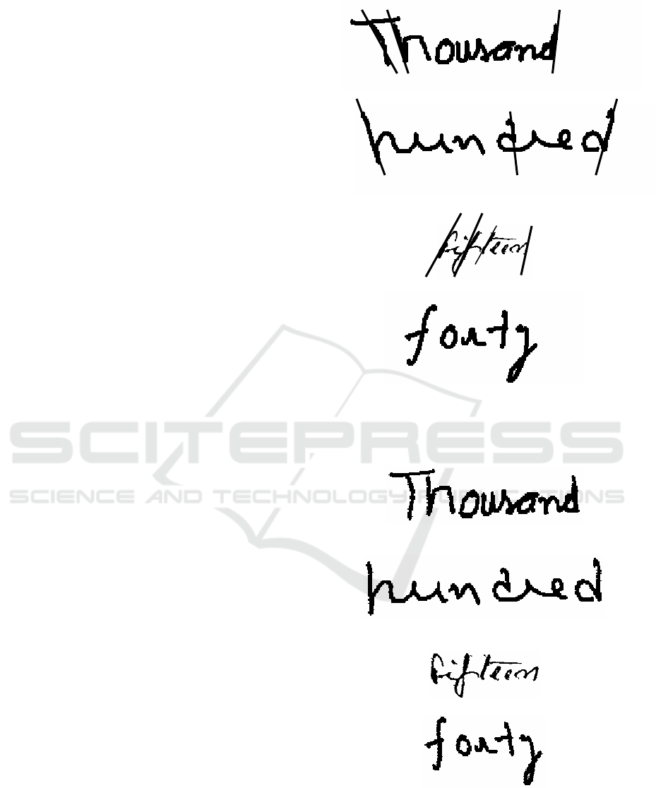
3 EXPERIMENTAL RESULTS
The proposed algorithm has been tested with more
than 1000 images containing the check amount in
words. The database of images includes both
machine-printed words and handwritten words. A
random set of handwritten words was selected, and
the results for the same are presented in Table1. The
samples were collected from 20 different people
who used pens with different thickness. As it can be
seen from the table, local slant correction works well
with images that contain words, such as thousand,
hundred, etc, which have sufficient number of long
strokes. For images containing words such as ‘one’
and ‘six’, which have very low probability of finding
a long vertical stroke, global slant correction
technique works well. The results for some sample
input images (Figure 4) are shown in Figure 5. As
evident, for images (i), (ii), (iii) in Figure 4,
sufficient number of local slants are present,
therefore local slant correction was applied.
Conversely, for image (iv) in Figure 4, no local slant
is present, therefore global slant correction is
applied.
The obtained results demonstrate high accuracy
of method, both qualitative and quantitative. Even
high degrees of slants in images were corrected, and
accurate results were clearly visible. Also, the
method was employed in a handwritten-word-
recognition system, which extracts features such as
vertical slants, descenders, etc., to recognize words.
After applying our method, there was a 15%
improvement in system’s handwritten-word-
recognition (CAERE & Kadmos) accuracy. The
improved accuracy is due to the method’s ability to
correctly choose between local and global slant
correction to be applied to a word.
(i)
(ii)
(iii)
(iv)
Figure 4: Input images and the selected strokes. (i)&(ii)
Images with three strokes; (iii) Image with four strokes, all
in almost same direction; (iv) Image without any stokes.
(i)
(ii)
(iii)
(iv)
Figure 5: (i), (ii) & (iii) Images with local slant correction
applied; (iv) Image with global slant correction applied.
VISAPP 2009 - International Conference on Computer Vision Theory and Applications
88

The timing details presented in table 2 has been
taken on Pentium IV system, 512MB RAM and no
application running on the system. All the images
used in experiment are 200 DPI images.
Table 1: Experimental Results.
Handwritten
word
Data Set
(376 images)
Global/Local
slant correction
(142/234)
‘one’ 13 11/2
‘two’ 12 8/4
‘three’ 12 2/10
‘four’ 12 9/3
‘five’ 12 8/4
‘six’ 12 12/0
‘seven’ 12 8/4
‘eight’ 17 4/8
‘nine’ 10 6/4
‘ten’ 12 6/6
‘eleven’ 12 4/8
‘twelve’ 12 2/10
‘thirteen’ 12 2/10
‘fourteen’ 6 1/5
‘fifteen’ 10 1/9
‘sixteen’ 10 5/5
‘seventeen’ 10 4/6
‘eighteen’ 10 3/7
‘ninteen’ 10 2/8
‘twenty’ 10 3/7
‘thirty’ 10 2/8
‘forty’ 13 2/8
‘fifty’ 9 1/8
‘sixty’ 6 3/3
‘seventy’ 12 4/8
‘eighty’ 12 6/6
‘ninty’ 10 4/6
‘hundred’ 20 2/18
‘thousand’ 25 3/22
‘million’ 10 2/8
‘billion’ 10 2/8
‘trillon’ 12 1/11
‘and’ 5 3/2
‘only’ 5 3/2
‘lakhs’ 10 3/7
‘crores’ 5 4/1
Table 2: Experimental Results (Execution time).
Slant correction technique
Average
Time taken
Only Local Slant Correction is applied 123 ms
Only Global Slant Correction is applied 72 ms
Programmatically identification of
appropriate technique (Global or Local)
& Correction
157 ms
4 CONCLUSIONS
In this paper, we presented an approach that works
very well for check images that have handwritten
words/text. However, this approach would work
equally well with any form of handwritten text. The
images, obtained after applying our method based on
this approach, were free of distortion. This is due to
the method’s remarkable ability to correctly choose
between local and global slant correction to be
applied to individual words.
REFERENCES
Bertolami, R., Uchida, S., Zimmermann, M. & Bunke H.,
2007. Non-Uniform Slant Correction for handwritten
Text Line Recognition, Proceedings of the 9th
International Conference on Document Analysis and
Recognition Vol 1 - Volume 01, Pages: 18-22, ISBN ~
ISSN:1520-5363 , 0-7695-2822-8.
Bozinovic, R.M. & Srihari, S.N., 1989. Off-Line Cursive
Script Word Recognition, IEEE Trans. PAMI, Vol. 11,
No. 1, pp. 68–83, Jan. 1989.
Chandra, Lal, Lal, Puja, Gupta, Raju, Tayal, Arun &
Ganotra, Dinesh, 2007. Improved Adaptive
Binarization Technique for Document Image Analysis,
2nd International Conference on Computer Vision
Theory and Applications.
Cote, M., Lecolinet, E., Cheriet, M. & Suen, C.Y., 1997.
Automatic reading of cursive scripts using a reading
model. International Journal on Document Analysis
and Recognition, Springer-Verlag 1998.
Datta, A. & Parui, S.K., 1994. A Robust Parallel Thinning
Algorithm for Binary Images. Pattern
Pyeoung Kee Kim 1997. Improving handwritten numeral
recognition using fuzzy logic. TENCON 97, IEEE
Region 10 Annual Conference. Speech and Image
Technologies for Computing and Telecommunications,
Proceedings of IEEE, Volume: 2, Pages 539-542
vol.2, ISBN: 0-7803-4365-4.
Uchida, S., Taira, E. & Sakoe, H, 2001. Nonuniform slant
correction using dynamic programming, Proceedings:
Sixth International Conference on Document Analysis
and Recognition, Volume , Issue , 2001 Page(s):434 –
438.
AN APPROACH FOR SLANT CORRECTION USING PROJECTIVE TRANSFORMATION
89
