
TELEOPERATION OF A MOBILE ROBOT VIA UMTS LINK
Florian Zeiger, Markus Sauer, Lothar Stolz
Zentrum f¨ur Telematik e.V., Allesgrundweg 12, Gerbrunn, Germany
Klaus Schilling
Institute of Computer Science, University of W¨urzburg, Am Hubland, W¨urzburg, Germany
Keywords:
Networked robotics, Teleoperation, UMTS, Wireless teleoperation, Wireless networks of robots.
Abstract:
Nowadays available broadband wireless communication technologies offer a broad spectrum of applications
and the todays availability of UMTS technology has a great potential in the area of networked robotics. This
work investigates teleoperation of mobile robots via UMTS communication links. First, several scenarios
with artificially generated command traffic between mobile robot and operator are analyzed in order to gain
knowledge of the link behavior. In a next step real mobile robot hardware is remote controlled via UMTS.
Thereby, the robot transmits sensor data and a video stream of its onboard camera while receiving commands
from the operator. The focus of this work is set on the measurement and analysis of the round trip time and the
packet inter-arrival time of data in different scenarios like the connection of two UMTS nodes, the connection
of an Internet PC and an UMTS node, or the behavior of several UMTS nodes generating a large amount
of data. The results clearly show how applications for mobile robot teleoperation can efficiently use UMTS
communication in order to allow seamless teleoperation between operator and hardware in distant locations.
1 INTRODUCTION
Communication is a very important issue in the area
of mobile robotics. This is especially the case in
networked multi-robot systems or joint human-robot
teams. Although many advances in autonomy have
been made in several applications like e.g. search
and rescue still direct teleoperation might be needed.
For direct teleoperation (Fong and Thorpe, 2001) the
communication link characteristics are even more im-
portant than for other applications where data might
not be as time-critical. From the human factors point
of view situational awareness (Endsley, 2000) is a
very critical aspect for robot teleoperation and can
be significantly influenced by communication param-
eters e.g. available bandwidth, delays, packet inter-
arrival time, and jitter for the payload data. For direct
teleoperation, often the camera image from the robot
is one of the major feedback elements for the human
operator from the remote environment. Therefore, a
relative high communication bandwidth, low delays
and a small jitter is desirable for these connections
in order to support maintaining situational aware-
ness. Nowadays, in robotics research either wire-
less LAN according to 802.11 (Ollero et al., 2003)
(Zeiger et al., 2008a) or proprietary communication
systems are used (Musial et al., 2001) (Pezeshkian
et al., 2007). The upcoming high-bandwidthnetworks
for mobile phones or mobile Internet like UMTS offer
a new widely used and commercially available tech-
nology with high potential for the application in mo-
bile robot teleoperation. Up to now, the coverage of
these networks has increased in a way that at least
all bigger cities have access to broadband networks.
This everywhere availability in large areas is a ma-
jor advantage for any telematic application compared
to a solution where infrastructure initially has to be
built up and maintenance effort is necessary. In par-
ticular, the application area of service robotics can
largely benefit from these characteristics. However
, the mobile phone networks like UMTS are designed
for different purposes and under different constraints.
Therefore, it is important to investigate the critical pa-
rameters of a communication technology like UMTS
in order to adjust the possible communication param-
eters on the application layer in a way to realize the
optimum usage of this technology.
The remainder of this work is structured as fol-
lows. Section 2 gives a brief introduction to the
UMTS technology. In Section 3, the test setup is de-
121
Zeiger F., Sauer M., Stolz L. and Schilling K.
TELEOPERATION OF A MOBILE ROBOT VIA UMTS LINK.
DOI: 10.5220/0002164901210126
In Proceedings of the 6th International Conference on Informatics in Control, Automation and Robotics (ICINCO 2009), page
ISBN: 978-989-674-000-9
Copyright
c
2009 by SCITEPRESS – Science and Technology Publications, Lda. All rights reserved

scribed. In Sections 4 and 5 the evaluations of the
tests are given. Also the results of the real mobile
robot hardware teleoperation test is presented. This
work concludes with a discussion of the results and
an outlook in Section 6.
2 UMTS BASICS
The Universal Mobile Telecommunications System
(UMTS) is a European standard for third generation
mobile telephony (3G). It is based on W-CDMA tech-
nology, standardized by the 3GPP, and implemts Eu-
ropean specifications of IMT-2000 ITU for third gen-
eration cellular radio systems. Although it is not a
worldwide standard, UMTS will probably become the
most popular one among its competitors. UMTS rig-
orously divides its infrastructure into two parts (cf.
Fig. 1). The UMTS Terrestrial Radio Access Net-
work (UTRAN) handles all tasks related to radio and
wireless networking and the Core Network (CN) pro-
vides all user services running via UMTS.
The UTRAN maintains the radio connection to
mobile operators for circuit and packet switched
links. A key to UMTS radio technology is the use
of the Wideband Code Division Multiple Access (W-
CDMA) user multiplexing procedure. W-CDMA
is responsible for ensuring that several participants
can communicate simultaneously using the same fre-
quency channel without interfering each other. The
UTRAN radio provides two different modes of oper-
ation: using UTRA-FDD mode, up- and downlink of
data run on separate frequencies. This mode supports
data rates up to 384 kbit/s. In UTRA-TDD mode,
up- and downlink take place at the same frequency,
but are separated by time slots. UTRA-TDD supports
data rates up to 2 Mbit/s but is quite uncommon com-
pared to UTRA-FDD. Since demand for higher data
rates emerged, UTRAN was enhanced by High Speed
Downlink Packet Access (HSDPA) as well as High
Speed Uplink Packet Access (HSUPA) to support data
rates up to 14.4 Mbit/s on downlink and 5.76 Mbit/s
on uplink. The UTRAN is composed of two basic
architectural components. Base stations (Node Bs)
provide the radio signaling. In addition, there are Ra-
dio Network Controllers (RNCs). Managing all radio
resources, these RNCs administrate a group of Node
Bs. The area covered by all Node Bs connected to
one RNC form a Radio Network Subsystem (RNS).
These RNSs are linked by cross connections of the
RNCs. sThe RNC finally makes the connection to the
Core Network (CN), too. Inside the CN, there are
several nodes providing various high level services
needed for mobile telecommunication. The Mobile
Switching Center (MSC) serves as a switching node
and gateway for circuit switched connections (phone
calls). In case of packet switched data (IP data), these
functionality is provided by the Serving GPRS Sup-
port Node (SGSN) and Gateway GPRS Support Node
(GGSN). For more details on UMTS please refer to
(Holma and Toskala, 2007).
Figure 1: UMTS architecture.
3 SCENARIO SETUP
The focus of this work is set on teleoperation of a
mobile robot via UMTS communication link and the
characterization of the communicationlink in order to
allow for a seamless teleoperation of the robot. There-
fore, three different test setups are analyzed:
• The connection between one robot connected to
UMTS and a PC connected to the Internet via
DSL (16 MBit/s) (Mode 1).
• The connection of two mobile robots via UMTS
(Mode 2). In this case, only the two robots gener-
ate traffic.
• The connection of two mobile robots via UMTS
while a third UMTS node in the same cell is
transmitting a large amount of data to the Inter-
net (Mode 3).
The mobile clients are represented by mini PCs which
are connected to the Internet via a USB UMTS device
(Huawei 3G modem). This device supports HSDPA
and HSUPA broadband data transmission besides the
normal UMTS mode. This broadband communica-
tion is used for all tests presented in this work. Cur-
rently, all UMTS access providers do not provide pub-
lic IP addresses or in case they do, only a small set
of services is supported. Therefore, each UMTS node
joins a virtual private network using openvpn(cf. Fig-
ure 1). Thus, a physical and hardware component is
present, and a logical overlay is set on top of this (cf.
ICINCO 2009 - 6th International Conference on Informatics in Control, Automation and Robotics
122
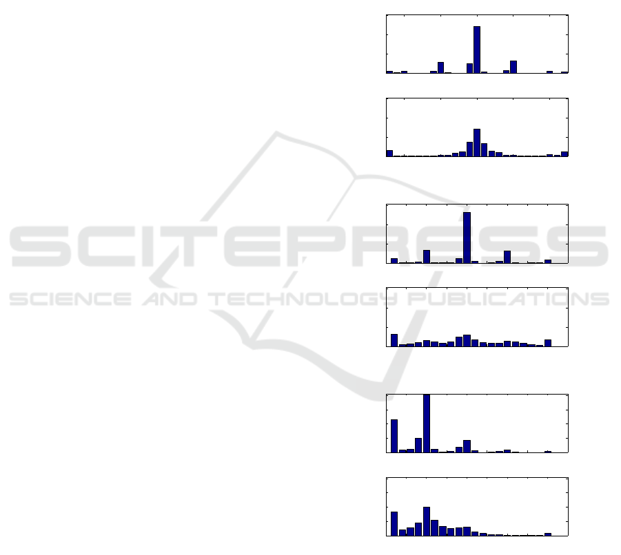
Fig. 1) which enables easy addressing of each mo-
bile node. Also the provided data services can be de-
fined according to the correspondingtest. Usually, the
UMTS specification promises a reliable packet trans-
mission every 20 milliseconds. To get an idea of the
link behavior, for each of the three above mentioned
modes, data streams of different sizes are generated.
As measurement categories, the packet inter-arrival
time is analyzed as this is an important criterion for
video and sensor data transmission and the round trip
time (rtt) is investigated as this two-way delay is also
very important in case the mobile robot is teleoperated
directly by a human operator. For the packet inter-
arrival time analysis, data is transmitted only one-way
and the packet inter-arrival time is plotted at the des-
tination node. Therefore, data is generated with a
packet size of 2048 bytes and a packet inter-departure
time of 10, 20, 50, and 100 milliseconds which results
in packet streams of 20, 40, 100, and 200 kb/s. The
round trip time measurements use ICMP ping packets
with the size manually set to 2040 bytes of payload
and 8 bytes ICMP header. Here, the send intervals
for ping packets are also set to 10, 20, 50, and 100
ms which generates data streams comparable to the
above described tests for the packet inter-arrival time.
Of course, the data stream for the round trip time tests
are transmitted in both directions.
4 EVALUATION
4.1 Packet Inter-arrival Time
For this analysis, the packet inter-arrival time at the
destination node is measured. Also the number of
packets is counted. The results are displayed in his-
tograms with a bin size of 2 milliseconds. The small-
est bin holds all values between 0 and its own value,
and the bin with the highest value holds also all larger
values up to infinity. The x-axis shows the packet
inter-arrival time in seconds and the y-axis shows the
relative frequency of occurrence. As the data set of
the measurements contains enough data to prove that
the resulting distribution is stable, the relative fre-
quency of occurrence can be considered as equal to
the probability of occurrence of the corresponding
packet inter-arrival time.
4.1.1 Connection between Internet PC and
UMTS Node
For this setup, the packet inter-arrival time is mea-
sured in both directions for packet streams of 20, 100,
and 200 kb/s. Figure 2a shows the results for the 20
kb/s stream. The packet inter-departure time for this
stream is 100 milliseconds. The upper subplot of Fig-
ure 2a shows, that more than 50% of the packets arrive
with an inter-arrival time of 100 ms. Approximately,
another 10% arrive with an inter-arrival time of 90
ms and 110 ms respectively. For the opposite direc-
tion – from UMTS node to Internet PC (cf. lower
subplot of Figure 2a)– the result is completely dif-
ferent. Here, the packet inter-arrival time is closely
distributed around the expected packet value of 100
milliseconds.
0.08 0.09 0.1 0.11 0.12
0
0.2
0.4
0.6
Internet to UMTS 20 kbytes/sec
packet inter−arrival time [s]
probability of occurence
0.08 0.09 0.1 0.11 0.12
0
0.2
0.4
0.6
UMTS to Internet 20 kbytes/sec
packet inter−arrival time [s]
probability of occurence
(a)
0 0.005 0.01 0.015 0.02 0.025 0.03 0.035 0.04 0.045
0
0.2
0.4
0.6
Internet to UMTS 100 kbytes/sec
packet inter−arrival time [s]
probability of occurence
0 0.005 0.01 0.015 0.02 0.025 0.03 0.035 0.04 0.045
0
0.2
0.4
0.6
UMTS to Internet 100 kbytes/sec
packet inter−arrival time [s]
probability of occurence
(b)
0 0.005 0.01 0.015 0.02 0.025 0.03 0.035 0.04 0.045
0
0.1
0.2
0.3
0.4
Internet to UMTS 200 kbytes/sec
packet inter−arrival time [s]
probability of occurence
0 0.005 0.01 0.015 0.02 0.025 0.03 0.035 0.04 0.045
0
0.1
0.2
0.3
0.4
UMTS to Internet 200 kbytes/sec
packet inter−arrival time [s]
probability of occurence
(c)
Figure 2: Packet inter-arrival time between Internet PC and
UMTS node and a data bandwidth of 20 kb/s (Fig. 2a) , 100
kb/s (Fig. 2b) and 200 kb/s (Fig. 2c).
For the stream with a bit rate of 100 kb/s, the re-
sults between the both investigated transmission di-
rections vary significantly (see Figure 2b). At the
TELEOPERATION OF A MOBILE ROBOT VIA UMTS LINK
123
UMTS node, more than 50% of the transmitted pack-
ets arrive with an inter-arrival-time of 20 ms and two
other peaks with 10% each are visible at about 10
ms and 30 ms. For the packet inter-arrival time for
the transmission direction from UMTS node to Inter-
net PC, only about 13% of the packets have an inter-
arrival time of 20 ms. Here, also small peaks at 10ms
and 30 ms (> 6% each), as well as a high amount of
packets with 5 ms or less (> 13%) and with 40 ms
or more (> 7%) are present. Also for the 200 kb/s
stream, the results for both directions are quite differ-
ent (cf. Figure 2c). For the transmission from Inter-
net PC to UMTS node more than 40% of the packets
have an inter-arrival time of 10 ms which corresponds
to the packet inter-departure time. More than 20% of
the packets have an inter-arrival time of 4ms and less.
For the other transmission direction – from UMTS to
internet PC – only about 20% of the packets arrive
with the expected inter-arrival time of 10 ms. A sec-
ond peak of about 18% is present for an inter-arrival
time of 4 ms and less. Most of the other packets are
distributed to inter-arrival times between 4 and 36 ms.
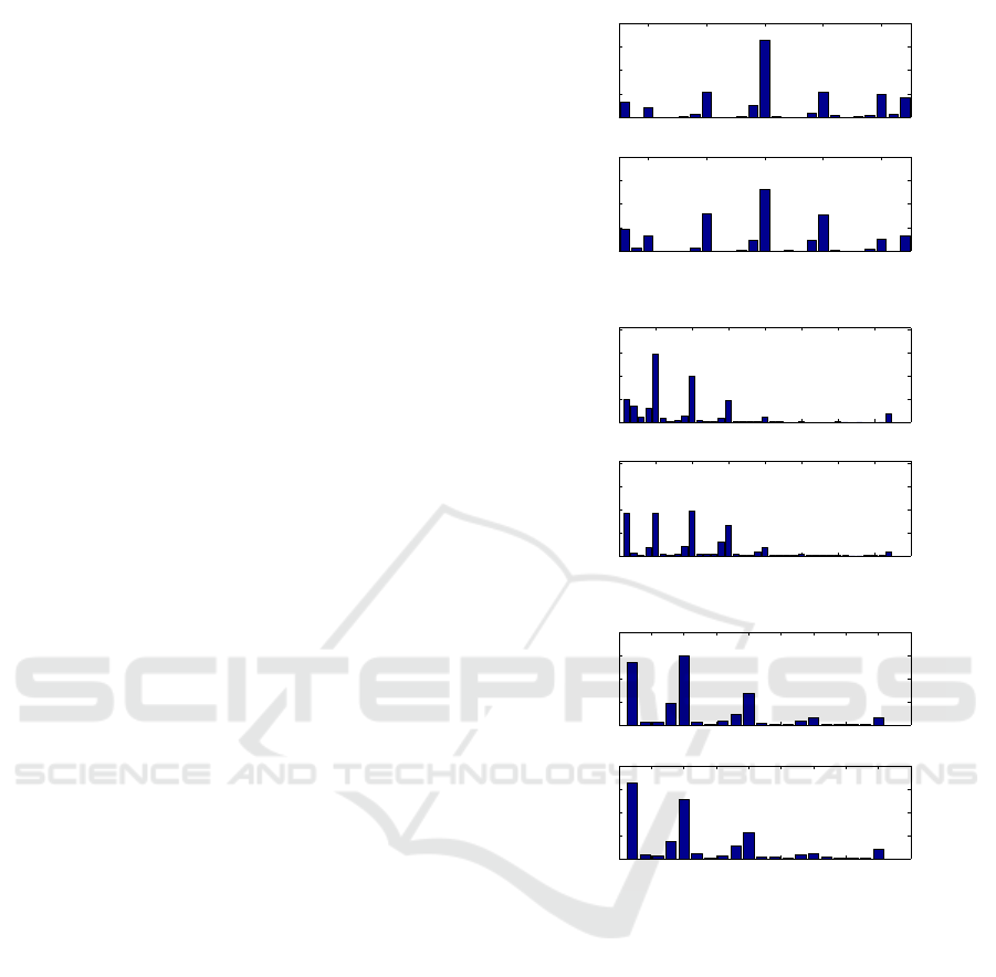
4.1.2 UMTS to UMTS Connection
This section shows the results of transmissions be-
tween two UMTS nodes. Each upper subplot of Fig-
ures 3a, 3b, and 3c show the packet inter-arrival times
when traffic is transmitted only between the two in-
volved nodes. The lower subplots of these Figures
show the inter-arrivaltime of the packets while a third
UMTS node transmits a large file to an Internet PC.
Thus, this data stream must share the UMTS cell
capacity with the measured data stream. Figure 3a
shows the results for the 20 kb/s stream. Here, both
setups show similar results. The majority of the pack-
ets has an inter-arrival time of 100 ms (33% without
additional traffic and 28% with additional traffic) and
almost all other inter-arrival times are distributed in
10 ms intervals at 80 ms, 90 ms, 110 ms, and 120 ms.
For this stream, the additionally generated traffic re-
duces the amount of the packets with an inter-arrival
time of 100 ms for approximately 5%. In Figure 3b
the results are displayed for the 100 kb/s stream with
a packet inter-departure time of 20 ms. In both situa-
tions, almost 20% of the packets have an inter-arrival
time of 20 ms. In case of no additionally generated
traffic, more than 55% of the packets arrive with an
inter-arrival time of less than 10 ms. In case addi-
tional trafficis generated, only about 42% of the pack-
ets have an inter-arrival time of 10 ms or less. The
remaining packet inter-arrival times are distributed at
peaks around 30 ms and 40 ms. The results of the 200
kb/s stream displayed in Figure 3c are similar to the
above described observations for the 100 kb/s stream.
0.08 0.09 0.1 0.11 0.12
0
0.1
0.2
0.3
0.4
UMTS to UMTS 20 kbytes/sec
packet inter−arrival time [s]
probability of occurence
0.08 0.09 0.1 0.11 0.12
0
0.1
0.2
0.3
0.4
UMTS to UMTS 20 kbytes/sec and additional traffic
packet inter−arrival time [s]
probability of occurence
(a)
0 0.01 0.02 0.03 0.04 0.05 0.06 0.07 0.08
0
0.1
0.2
0.3
0.4
UMTS to UMTS 100 kbytes/sec
packet inter−arrival time [s]
probability of occurence
0 0.01 0.02 0.03 0.04 0.05 0.06 0.07 0.08
0
0.1
0.2
0.3
0.4
UMTS to Internet 100 kbytes/sec and additional traffic
packet inter−arrival time [s]
probability of occurence
(b)
0 0.005 0.01 0.015 0.02 0.025 0.03 0.035 0.04 0.045
0
0.1
0.2
0.3
0.4
UMTS to UMTS 200 kbytes/sec
packet inter−arrival time [s]
probability of occurence
0 0.005 0.01 0.015 0.02 0.025 0.03 0.035 0.04 0.045
0
0.1
0.2
0.3
0.4
UMTS to Internet 200 kbytes/sec and additional traffic
packet inter−arrival time [s]
probability of occurence
(c)
Figure 3: Packet inter-arrival time between UMTS nodes
and a data bandwidth of 20 kb/s (Fig. 3a), 100 kb/s (Fig.
3b), and 200 kb/s (Fig. 3c).
The additionally generated traffic reduces the amount
of packets at the expected inter-arrival time of 10 ms
for about 5% and the remaining packets are again lo-
cated at the bins with 10 ms inter-bin distance and
inter-arrival times of less than 4 ms, 20 ms, 30 ms,
and 40 ms.
Finally, the effective receiving bit rates of the pay-
load data is shown in Tables 1a and 1b. Table 1a
shows the results of the test runs between UMTS node
and Internet PC and Table 1b shows the results of the
test between two UMTS nodes without additionally
generated traffic (Mode 2) and between two UMTS
nodes with additionally generated traffic (Mode 3).
These two tables give an idea of the present packet
ICINCO 2009 - 6th International Conference on Informatics in Control, Automation and Robotics
124
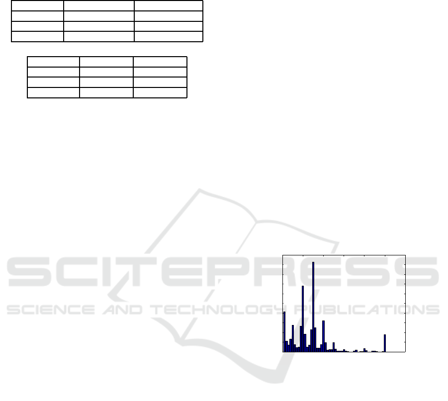
Table 1: Resulting effective payload bit rates at the receiv-
ing node between UMTS node and Internet PC (Table 1a)
and for Mode 2 and Mode 3 (Table 1b).
sending data rate receiving at UMTS node receiving at Internet PC
20 kbytes/s 19.20 kbytes/s 19.58 kbytes/s
100 kbytes/s 98.09 kbytes/s 92.62 kbytes/s
200 kbytes/s 194.33 kbytes/s 162.82 kbytes/s
(a)
sending data rate receiving Mode 2 receiving Mode 3
20 kbytes/s 16.19 kbytes/s 19.31 kbytes/s
100 kbytes/s 94.03 kbytes/s 92.53 kbytes/s
200 kbytes/s 141.80 kbytes/s 125.61 kbytes/s
(b)
loss during the test runs. Surprisingly good results
are achieved for all data streams during the transmis-
sion from Internet PC to UMTS node. In the oppo-
site direction, an increased packet loss is observed for
the 200 kb/s stream. For Mode 2 and Mode 3, where
two UMTS nodes communicated with each other, the
packet loss was significantly higher.
4.2 Round Trip Times
Figure 4 shows the measured rtts for the generated
packet streams. Mode 1 corresponds to the Internet-
UMTS node scenario, Mode 2 is the transmission be-
tween two UMTS nodes without additionally gener-
ated traffic and for Mode 3, the data exchange of two
UMTS nodes is measured while a third node trans-
mits additional data to an Internet PC. These box-
plots show the median of the measured values (hor-
izontal line) and the box shows 50% of the values
boundedby the lower 25% quartile and the upper 75%
quartile. Furthermore, lines indicate the most extreme
values within 1.5 times the interquartile range from
the ends of the box and extreme values lying out-
side this borders are marked with crosses. For the
three streams with 20 kbyte/s, 50% of the measured
rtt values are distributed very close to the correspond-
ing median. A similar observation can be made for
the 40 kbyte/s stream in Mode 1 and Mode 3, and for
the 100 kbyte/s stream in the Mode 1 scenario. As ex-
pected, the largest variations appear for the high band-
width streams with 200 kbyte/s and the 100 kbyte
stream in Mode 3 with the additionally generated traf-
fic. In general, 50% of the measured rtt values of each
test run are located close to the corresponding me-
dian. Only few extreme values are measured below
the lower 25% quartile border and sometimes, very
high rtt values are measured above the upper border of
the 75% quartile (e.g. for 100 kb/s in Mode 3). Thus,
the later used application to mobile robotics must con-
sider these high round trip times which occur some-
times and must be able to handle this large variability.
5 REAL HARDWARE TEST
To analyze the UMTS link under real conditions for
mobile robot teleoperation, a Pioneer 3-AT is tele-
operated from a Laptop via UMTS. The robot plat-
form is equipped with a mini PC and a network video
camera AXIS 221 and transmits a motion JPEG video
stream with a resolution of 320x240 and a frame rate
of 15 frames per second. The Player version 2.0.4
software is used to interface the hardware and for
providing communication between the client and the
hardware. The client is a Java program which pro-
vides a video image of the mobile robot’s onboard
camera and displays sensor data. During the test runs,
the mobile robot generates a sensor data stream and
sends it to the Laptop. Additionally, video data is sent
each 66.66 ms. The Client program is sending control
commands with a bit rate of 1.2 kb/s. In Figure 5, the
behavior of the video data which arrives at the oper-
ator’s PC is shown. The video source generates rela-
tively large packets which must be fragmented. Thus,
the send buffers are continuously filled and packets
are sent as often as possible. On the receiver’s side,
the already above observed peaks of the packet inter-
arrival times each 10 ms is also visible.
0 0.02 0.04 0.06 0.08 0.1 0.12
0
0.02
0.04
0.06
0.08
0.1
0.12
0.14
0.16
0.18
0.2
packet inter−arrival time [s]
relative frequency of occurence
Figure 5: Packet inter-arrival of the video data coming from
the mobile robot.
6 DISCUSSION OF THE RESULTS
The above presented results show clearly that UMTS
is a well suited communication technology for the
teleoperation of mobile robots. The results obtained
in the initial test runs with the artificially generated
command traffic give a detailed overview of the chan-
nel behavior. When data is transmitted from the
UMTS node via the UMTS infrastructure and the In-
ternet, the arriving packets at the PC have a higher
variance in the packet inter arrival time as typically,
the Internet data transfer induces such a variance. In
the opposite direction, the packets arrive at the UMTS
infrastructure via the Internet. Then the UMTS infras-
tructure is responsible for further data transmission
TELEOPERATION OF A MOBILE ROBOT VIA UMTS LINK
125
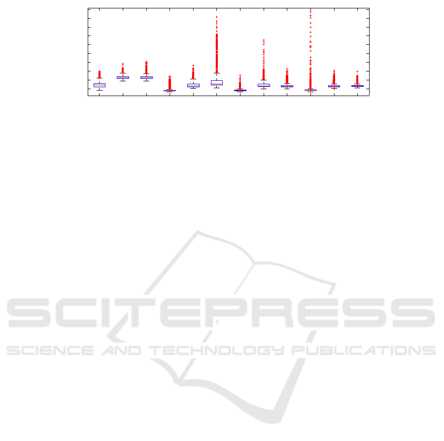
200 kb/s (1) 200 kb/s (2) 200 kb/s (3) 100 kb/s (1) 100 kb/s (2) 100 kb/s (3) 40 kb/s (1) 40 kb/s (2) 40 kb/s (3) 20 kb/s (1) 20 kb/s (2) 20 kb/s (3)
200
400
600
800
1000
1200
1400
1600
1800
2000
round trip time [ms]
generated traffic stream
Figure 4: Round trip times in milliseconds (Mode (1): Internet-UMTS; Mode (2): UMTS-UMTS; Mode (3): UMTS-UMTS
and additional traffic).
and takes care that packets are transmitted with de-
fined packet inter-departuretimes. These packet inter-
departure times are depending on the used bandwidth
and the used HSDPA/HSUPA mode and some other
aspects depending on the provider. Nevertheless, the
measured packet inter-arrival times are now bound to
fixed times which reduces the variance. In general, it
can be seen that as soon as the broadband communi-
cation mode is entered, data is delivered at the mobile
robot and at the operator’s PC constantly. Noticeable
outcomes are the frequent packet inter-arrival times
at 10 ms and multiple of 10 ms with a relatively high
peak at the 20 ms inter-arrival times. Also, the re-
ceived effective payload data rates give a clear view
of the present packet loss during the tests. Finally, the
measured round trip times and their distribution lead
to the following hints for implementing mobile robot
teleoperation. The ”just plug and try” setup which
is described in Section 5 shows to be already usable.
Nevertheless, a defined traffic shaping might be a suit-
able approach to use the characteristics of the UMTS
link more efficient and to increase the quality of tele-
operation (e.g. better video quality or less packet
loss). Approaches for this idea are already published
in another context (Zeiger et al., 2008c)(Zeiger et al.,
2008b) and shows to be a useful technique. Neverthe-
less, UMTS is a promising technology to allow broad-
band communication for hardware teleoperation and
will be in the research focus of networked robotics
in near future. Future work will be set on analyzing
more details of the UMTS link in combination with
mobile robot teleoperation. Open issues are how to
use the behavior of the communication channel in or-
der to allow for high quality onboard video transmis-
sion together with reliable control data transmission
in both directions.
ACKNOWLEDGEMENTS
This work is partially supported by the European
Union and the Federal State of Bavaria in the frame
of the EFRE program.
REFERENCES
Endsley, M. R. (2000). Theoretical underpinnings of sit-
uation awareness: A critical review. In Endsley,
M. R. and Garland, D. J., editors, Situation aware-
ness analysis and measurement, chapter 1, pages 3–
26. Lawrence Erlbaum Associates.
Fong, T. and Thorpe, C. (2001). Vehicle teleoperation inter-
faces. Auton. Robots, 11(1):9–18.
Holma, H. and Toskala, A., editors (2007). WCDMA for
UMTS: HSPA Evolution and LTE. John Wiley& Sons,
Ltd, fourth edition.
Musial, M., Brandenburg, U. W., and Hommel, G. (2001).
Success of an Inexpensive System Design: The Flying
Robot MARVIN. In 16th Int. Unmanned Air Vehicle
System Conf. (UAVs).
Ollero, A., Alcazar, J., Cuesta, F., Lopez-Pichaco, F., and
Nogales, C. (2003). Helicopter teleoperation for aerial
monitoring in the comets multi-uav system. In 3rd
IARP Workshop on Service, Assistive and Personal
Robots (IARP 2003), Madrid (Spain).
Pezeshkian, N., Nguyen, H. G., and Burmeister, A. (2007).
Unmanned ground vehicle radio relay deployment
system for non-line-of-sight operations. In Proc. of
the 13th IASTED Int. Conf. on Robotics and Applica-
tions, August 29-31, W¨urzburg, Germany, RA2007.
Zeiger, F., Kr¨amer, N., and Schilling, K. (2008a). Com-
manding mobile robots via wireless ad-hoc networks
- a comparison of four ad-hoc routing protocol imple-
mentations. In IEEE Int. Conf. on Robotics and Au-
tomation (ICRA 2008).
Zeiger, F., Sauer, M., and Schilling, K. (2008b). Intelligent
Shaping of a Video Stream for Mobile Robot Tele-
operation via Multihop Networks in Real-World Sce-
narios. In Proc. of IEEE/RSJ Int. Conf. on Intelligent
Robots and Systems (IROS 2008).
Zeiger, F., Sauer, M., and Schilling;, K. (2008c). Video
Transmission with Adaptive Quality based on Net-
work Feedback for Mobile Robot Teleoperation in
Wireless Multi-Hop Networks. In 5th Int. Conf. on In-
formatics, Automation and Robotics (ICINCO 2008).
ICINCO 2009 - 6th International Conference on Informatics in Control, Automation and Robotics
126
