
MODULATION-MODE AND POWER ASSIGNMENT IN
SVD-ASSISTED BROADBAND MIMO SYSTEMS
Andreas Ahrens
Hochschule Wismar, University of Technology, Business and Design, Philipp-M¨uller-Straße 14, 23966 Wismar, Germany
C´esar Benavente-Peces
Universidad Polit´ecnica de Madrid, Ctra. Valencia. km. 7, 28031 Madrid, Spain
Keywords:
Multiple-Input Multiple-Output System, Singular-Value Decomposition, Bit Allocation, Power Allocation,
Wireless Transmission.
Abstract:
Existing bit loading and transmit power allocation techniques are often optimized for maintaining both a fixed
transmit power and a fixed target bit-error rate while attempting to maximize the overall data-rate. However,
delay-critical real-time interactive applications, such as voice or video transmission, may require a fixed data
rate. For these fixed-rate applications it is desirable to design algorithms, which minimize the bit-error rate
(BER) at a given fixed data rate. Since the capacity of multiple-input multiple-output (MIMO) systems in-
creases linearly with the minimum number of antennas at both, the transmitter as well as the receiver side,
MIMO schemes have attracted a lot of attention. However, non-frequency selective MIMO links have reached
a state of maturity. By contrast, frequency selective MIMO links require substantial further research, leading
in this contribution to a joint optimization of the number of activated MIMO layers and the number of bits per
symbol along with the appropriate allocation of the transmit power under the constraint of a given fixed data
throughput. Our results show that in order to achieve the best possible bit-error rate, not necessarily all MIMO
layers have to be activated.
1 INTRODUCTION
The requirements for transmission capacity for
speech, data and multimedia information will proba-
bly increase continuously in the future. With the lim-
itation of available resources such as transmit power
or bandwidth, the demand to increase the spectral ef-
ficiency of future transmission systems is clearly rec-
ognizable. In order to comply with the demand on in-
creasing available data rates in particular in wireless
technologies, systems with multiple transmit and re-
ceive antennas, also called MIMO systems (multiple-
input multiple-output), have become indispensable
and can be considered as an essential part of increas-
ing both the achievable capacity and integrity of fu-
ture generations of wireless systems (K¨uhn, 2006;
Zheng and Tse, 2003). In general, the most beneficial
choice of the number of activated MIMO layers and
the number of bits per symbol along with the appro-
priate allocation of the transmit power offer a certain
degree of design freedom, which substantially affects
the performance of MIMO systems. The well-known
water-filling technique is virtually synonymous with
adaptive modulation (Krongold et al., 2000; Jang and
Lee, 2003; Park and Lee, 2004; Zhou et al., 2005) and
it is used for maximizing the overall data rate. Since
delay-critical applications, such as voice or streaming
video, may require a certain fixed data rate, the effi-
ciency of fixed transmission modes is studied in this
contribution regardless of the channel quality. How-
ever, non-frequency selective MIMO links have at-
tracted a lot of research and have reached a state of
maturity (Ahrens and Lange, 2008). By contrast, fre-
quency selective MIMO links require substantial fur-
ther research, where spatio-temporal vector coding
(STVC) introduced by RALEIGH seems to be an ap-
propriate candidate for broadband transmission chan-
nels (Raleigh and Cioffi, 1998; Raleigh et al., 1999).
Here it can be shown that multipath propagation is no
longer a limiting factor in data transmission (Gesbert,
2004). Against this background, the novel contribu-
tion of this paper is that we demonstrate the benefits
83
Ahrens A. and Benavente-Peces C. (2009).
MODULATION-MODE AND POWER ASSIGNMENT IN SVD-ASSISTED BROADBAND MIMO SYSTEMS.
In Proceedings of the International Conference on Wireless Information Networks and Systems, pages 83-88
DOI: 10.5220/0002165700830088
Copyright
c
SciTePress

of amalgamating a suitable choice of activated MIMO
layers and number of bits per symbol along with the
appropriate allocation of the transmit power under the
constraint of a given data throughput. The remaining
part of this paper is organized as follows: Section 2
introduces the system model and the considered qual-
ity criteria are briefly reviewed in section 3. The pro-
posed solutions of bit and power allocation are dis-
cussed in section 4, while the associated performance
results are presented and interpreted in section 5. Fi-
nally, section 6 provides some concluding remarks.
2 SYSTEM MODEL
When considering a frequency selective SDM MIMO
link, composed of n
T
transmit and n
R
receive anten-
nas, the block-oriented system is modelled by
u = H·c+ w . (1)
In (1), c is the (N
T
×1) transmitted signal vector con-
taining the complex input symbols transmitted over
n
T
transmit antennas in K consecutive time slots, i.e.,
N
T
= K n
T
. This vector can be decomposed into n
T
antenna-specific signal vectors c
µ
according to
c =
c
T
1
,.. . ,c
T
µ
,.. . ,c
T
n
T
T
. (2)
In (2), the (K × 1) antenna-specific signal vector
c
µ
transmitted by the transmit antenna µ (with µ =
1,... ,n
T
) is modelled by
c
µ
=
c
1µ
,.. .,c
kµ
,.. .,c
K µ
T
. (3)
The (N
R
×1) received signal vector u, defined in (1),
can again be decomposed into n
R
antenna-specific
signal vectors u
ν
(with ν = 1,..., n
R
) of the length
K + L
c
, i.e., N
R
= (K + L
c
)n
R
, and results in
u =
u
T
1
,.. .,u
T
ν
,.. .,u
T
n
R
T
. (4)
By taking the (L
c
+ 1) non-zero elements of the re-
sulting symbol rate sampled overall channel impulse
response between the µth transmit and νth receive an-
tenna into account, the antenna-specific received vec-
tor u
ν
has to be extended by L
c
elements, compared to
the transmitted antenna-specific signal vector c
µ
de-
fined in (3). The ((K + L
c
) ×1) signal vector u
ν
re-
ceived by the antenna ν (with ν = 1, ... , n
R
) can be
constructed, including the extension through the mul-
tipath propagation, as follows
u
ν
=
u
1ν
,u
2ν
,.. .,u
(K+L
c
)ν
T
. (5)
Similarly, in (1) the (N
R
×1) noise vector w results in
w =
w
T
1
,.. .,w
T
ν
,.. .,w
T
n
R
T
. (6)
The vector w of the additive, white Gaussian noise
(AWGN) is assumed to have a variance of U
2
R
for both
the real and imaginary parts and can still be decom-
posed into n
R
antenna-specificsignal vectors w
ν
(with
ν = 1,..., n
R
) according to
w
ν
=
w
1ν
,w
2ν
,.. .,w
(K+L
c
)ν
T
. (7)
Finally, the (N
R
×N
T
) system matrix H of the block-
oriented system model, introduced in (1), results in
H =
H
11
... H
1n
T
.
.
.
.
.
.
.
.
.
H
n
R
1
··· H
n
R
n
T
, (8)
and consists of n
R
n
T
single-input single-output
(SISO) channel matrices H
νµ
(with ν = 1, ... , n
R
and
µ = 1,.. .,n
T
). The system description, called spatio-
temporal vector coding (STVC), was introduced by
RALEIGH. Every of theses matrices H
νµ
with the di-
mension ((K + L
c
)×K) describes the influence of the
channel from transmit antenna µ to receive antenna ν
including transmit and receive filtering. The channel
convolution matrix H
νµ
between the µth transmit and
νth receive antenna is obtained by taking the (L
c
+ 1)
non-zero elements of resulting symbol rate sampled
overall impulse response into account and results in:
H
νµ
=
h
0
0 0 ··· 0
h
1
h
0
0 ···
.
.
.
h
2
h
1
h
0
··· 0
.
.
. h
2
h
1
··· h
0
h
L
c
.
.
. h
2
··· h
1
0 h
L
c
.
.
. ··· h
2
0 0 h
L
c
···
.
.
.
0 0 0 ··· h
L
c
. (9)
Throughout this paper, it is assumed that the (L
c
+ 1)
channel coefficients, between the µth transmit and νth
receive antenna have the same averaged power and
undergo a Rayleigh distribution. Furthermore,a block
fading channel model is applied, i. e., the channel is
assumed to be time invariant for the duration of one
SDM MIMO data vector.
The interference between the different antenna’s
data streams, which is introduced by the off-diagonal
elements of the channel matrix H, requires appropri-
ate signal processing strategies. A popular technique
is based on the singular-value decomposition (SVD)
(Haykin, 2002) of the system matrix H, which can be
written as H = S·V·D
H
, where S and D
H
are unitary
matrices and V is a real-valued diagonal matrix of the
positive square roots of the eigenvalues of the matrix
WINSYS 2009 - International Conference on Wireless Information Networks and Systems
84

c
ℓ,k
y
ℓ,k
˜w
ℓ,k
p
ξ
ℓ,k
Figure 1: Resulting layer-specific SDM MIMO system
model (with ℓ = 1,2,. .. , L and k = 1,2,... , K).
H
H
H sorted in descending order
1
. The SDM MIMO
data vector c is now multiplied by the matrix D be-
fore transmission. In turn, the receiver multiplies the
received vector u by the matrix S
H
. Thereby neither
the transmit power nor the noise power is enhanced.
The overall transmission relationship is defined as
y = S
H
(H·D·c+ w) = V·c+ ˜w. (10)
As a consequence of the processing in (10), the chan-
nel matrix H is transformed into independent, non-
interfering layers having unequal gains.
3 QUALITY CRITERIA
In general, the quality of data transmission can be in-
formally assessed by using the signal-to-noise ratio
(SNR) at the detector’s input defined by the half ver-
tical eye opening and the noise power per quadrature
component according to
ρ =
(Half vertical eye opening)
2
Noise Power
=
(U
A
)
2
(U
R
)
2
, (11)
which is often used as a quality parameter (Ahrens
and Lange, 2008). The relationship between the
signal-to-noise ratio ρ = U
2
A
/U
2
R
and the bit-error
probability evaluated for AWGN channels and M-ary
Quadrature Amplitude Modulation (QAM) is given
by (Proakis, 2000)
P
BER
=
2
log
2
(M)
1−
1
√
M
erfc
r
ρ
2
. (12)
When applying the proposed system structure, the
SVD-based equalization leads to different eye open-
ings per activated MIMO layer ℓ (with ℓ = 1,2,.. .,L)
at the time k (with k = 1,2,.. .,K) within the SDM
MIMO signal vector according to
U
(ℓ,k)
A
=
q
ξ
ℓ,k
·U
sℓ
, (13)
where U
sℓ
denotes the half-level transmit amplitude
assuming M
ℓ
-ary QAM and
p
ξ
ℓ,k
represents the cor-
responding positive square roots of the eigenvalues of
the matrix H
H
H (Figure 1). Together with the noise
1
The transpose and conjugate transpose (Hermitian) of
D are denoted by D
T
and D
H
, respectively.
powerper quadraturecomponent,the SNR per MIMO
layer ℓ at the time k becomes
ρ
(ℓ,k)
=
U
(ℓ,k)
A
2
U
2
R
= ξ
ℓ,k
(U
sℓ
)
2
U
2
R
. (14)
Using the parallel transmission over L ≤ min(n
T
,n
R
)
MIMO layers, the overall mean transmit power be-
comes P
s
=
∑
L
ℓ=1
P
sℓ
, where the number of readily
separable layers
2
is limited by min(n
T
,n
R
). Consider-
ing QAM constellations, the average transmit power
P
sℓ
per MIMO layer ℓ may be expressed as (Proakis,
2000)
P
sℓ
=
2
3
U
2
sℓ
(M
ℓ
−1) . (15)
Combining (14) and (15), the layer-specific SNR at
the time k results in
ρ
(ℓ,k)
= ξ
ℓ,k
3
2(M
ℓ
−1)
P
sℓ
U
2
R
. (16)
In order to transmit at a fixed data rate while maintain-
ing the best possible integrity, i. e., bit-error rate, an
appropriate number of MIMO layers has to be used,
which depends on the specific transmission mode, as
detailed in Table 1. In general, the BER per SDM
MIMO data vector is dominated by the specific trans-
mission modes and the characteristics of the singu-
lar values, resulting in different BERs for the differ-
ent QAM configurations in Table 1. An optimized
adaptive scheme would now use the particular trans-
mission modes, e. g., by using bit auction procedures
(Wong et al., 1999), that results in the lowest BER
for each SDM MIMO data vector. This would lead to
different transmission modes per SDM MIMO data
vector and a high signaling overhead would result.
However, in order to avoid any signalling overhead,
fixed transmission modes are used in this contribution
regardless of the channel quality. The MIMO layer
specific bit-error probability at the time k after SVD
is given by
P
(ℓ,k)
BER
=
2
1−
1
√
M
ℓ
log
2
(M
ℓ
)
erfc
s
ρ
(ℓ,k)
2
. (17)
The resulting average bit-error probability at the time
k assuming different QAM constellation sizes per ac-
tivated MIMO layer results in
P
(k)
BER
=
1
∑
L
ν=1
log
2
(M
ν
)
L
∑
ℓ=1
log
2
(M
ℓ
)P
(ℓ,k)
BER
. (18)
2
It is worth noting that with the aid of powerful non-
linear near Maximum Likelihood (ML) sphere decoders it
is possible to separate n
R
> n
T
number of layers (Hanzo
and Keller, 2006).
MODULATION-MODE AND POWER ASSIGNMENT IN SVD-ASSISTED BROADBAND MIMO SYSTEMS
85

Table 1: Investigated transmission modes.
throughput layer 1 layer 2 layer 3 layer 4
8 bit/s/Hz 256 0 0 0
8 bit/s/Hz 64 4 0 0
8 bit/s/Hz 16 16 0 0
8 bit/s/Hz 16 4 4 0
8 bit/s/Hz 4 4 4 4
Taking K consecutive time slots into account, needed
to transmit the SDM MIMO data vector, the aggre-
gate bit-error probability per SDM MIMO data vector
yields
P
BERblock
=
1
K
K
∑
k=1
P
(k)
BER
. (19)
When considering time-variant channel conditions,
rather than an AWGN channel, the BER can be de-
rived by considering the different transmission block
SNRs.
Assuming that the transmit power is uniformly
distributed over the number of activated MIMO lay-
ers, i.e., P
sℓ
= P
s
/L, the half-level transmit amplitude
U
sℓ
per activated MIMO layer results in
U
sℓ
=
s
3P
s
2L(M
ℓ
−1)
. (20)
Finally, the layer-specific signal-to-noise ratio at the
time k, defined in (14), results together with (20) in
ρ
(ℓ,k)
= ξ
ℓ,k
3
2L(M
ℓ
−1)
P
s
U
2
R
= ξ
ℓ,k
3
L(M
ℓ
−1)
E
s
N
0
. (21)
4 ADAPTIVE MIMO-LAYER PA
In systems, where channel state information is avail-
able at the transmitter side, the knowledge about how
the symbols are attenuated by the channel can be used
to adapt the transmit parameters. Power allocation
(PA) can be used to balance the bit-error probabili-
ties in the activated MIMO layers. Adaptive power
allocation has been widely investigated in the litera-
ture (Krongold et al., 2000; Jang and Lee, 2003; Park
and Lee, 2004; Ahrens and Lange, 2008). The BER
of the uncoded MIMO system is dominated by the
specific layers having the lowest SNR’s. As a rem-
edy, a MIMO-layer transmit PA scheme is required
for minimizing the overall BER under the constraint
of a limited total MIMO transmit power. The pro-
posed PA scheme scales the half-level transmit ampli-
tude U
sℓ
of the ℓth MIMO layer by the factor
√
p
ℓ,k
.
This results in a MIMO layer-specific transmit ampli-
tude of U
sℓ
√
p
ℓ,k
for the QAM symbol of the transmit
data vector transmitted at the time k over the MIMO
layer ℓ.Applying MIMO-layer PA, the half vertical
eye opening per MIMO layer ℓ at the time k becomes
U
(ℓ,k)
PA
=
√
p
ℓ,k
·
q
ξ
ℓ,k
·U
sℓ
. (22)
Now the layer-specific signal-to-noise ratio, defined
in (21), is changed to
ρ
(ℓ,k)
PA
=
U
(ℓ,k)
PA
2
U
2
R
= p
ℓ,k
·
3ξ
ℓ,k
L(M
ℓ
−1)
E
s
N
0
= p
ℓ,k
·ρ
(ℓ,k)
.
(23)
Applying MIMO-layer PA, the information about
how the symbols are attenuated by the channel, i.e.,
the singular-values, has to be sent via a feedback
channel to the transmitter side and leads to a high sig-
nalling overhead that is contradictory to the fix trans-
mission modes that require no signalling overhead.
However, as shown in (Ahrens and Lange, 2009) a
vector quantizer (VQ) can be used to keep the sig-
nalling overhead moderate. Here, a VQ for the power
allocation parameters instead of the singular values
guarantees a better adaption at a given codebook
size, since the power level vectors has less or equal
dimensions than the singular-value vectors (Ahrens
and Lange, 2009). Moreover, its elements are much
smaller digits ranged from 0 to 1, rather than from 0
to +∞ in the singular-value vector case. Hence, the
entropy of the power level vectors is smaller, which
benefits the quantization accuracy and the feedback
overhead.
The aim of the forthcoming discussions is now the
determination of the values
√
p
ℓ,k
for the activated
MIMO layers. A common strategy is to use the La-
grange multiplier method in order to find the optimal
value of
√
p
ℓ,k
for each MIMO layer ℓ and time k
needed to transmit the SDM MIMO data vector (Park
and Lee, 2004). Unfortunately, the Lagrange mul-
tiplier method often leads to excessive-complexity
optimization problems (Ahrens and Lange, 2008).
Therefore, suboptimal power allocation strategies
having a lower complexity are of common interest. A
natural choice is to opt for a PA scheme, which results
in an identical signal-to-noise ratio
ρ
(ℓ,k)
PAequal
=
U
(ℓ,k)
PAequal
2
U
2
R
= p
ℓ,k
·ρ
(ℓ,k)
(24)
for all activated MIMO layers at the time k, i. e., in
ρ
(ℓ,k)
PAequal
= constant ℓ = 1,2, ··· ,L . (25)
The power to be allocated to each activated MIMO
layer at the time k can be shown to be calculated as
WINSYS 2009 - International Conference on Wireless Information Networks and Systems
86
follows (Ahrens and Lange, 2008):
p
ℓ,k
=
(M
ℓ
−1)
ξ
ℓ,k
·
L
L
∑
ν=1
(M
ν
−1)
ξ
ν,k
. (26)
The only difference between the optimum PA and the
equal SNR PA is the consideration of the factor (1−
1/
√
M
ℓ
) by the optimum PA. Taking (26), (22) and
(20) into account, for each symbol of the SDM MIMO
data vector, transmitted at the time k over the number
of activated MIMO layers, the same half vertical eye
opening can be guaranteed, i. e.,
U
(ℓ,k)
PAequal
= constant ℓ = 1,2, ··· ,L . (27)
When assuming an identical detector input noise vari-
ance for each channel output symbol, the above-
mentioned equal quality scenario (25) is encountered
and nearly the same BER can be achieved on all ac-
tivated MIMO layers at a given time k. However,
different BERs arise for the K consecutive time slots
needed to transmit a given SDM MIMO data vector.
Therefore, the BER per SDM MIMO signal vector is
mainly dominated by the symbol positions having the
lowest SNR’s. Furthermore, taking the time-variant
nature of the transmission channel into account, dif-
ferent BERs arise for different SDM MIMO data
blocks. In order to overcome this problem, the num-
ber of transmit or receive antennas has to be increased
or coding over the different data blocks should be
used.
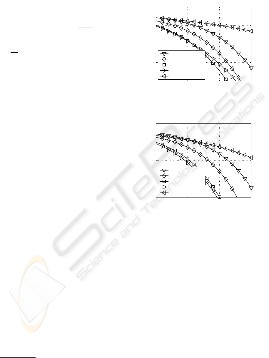
5 RESULTS
In this contribution the efficiency of fixed transmis-
sion modes is studied regardless of the channel qual-
ity. Assuming predefined transmission modes, a fixed
data rate can be guaranteed. The obtained BER curves
are depicted in Figure 2 and 3 for the different QAM
constellation sizes and MIMO configurations of Ta-
ble 1, when transmitting at a bandwidth efficiency
of 8 bit/s/Hz within a given bandwidth
3
. Assum-
ing a uniform distribution of the transmit power over
the number of activated MIMO layers, it turns out
that not all MIMO layers have to be activated in or-
der to achieve the best BERs. Comparing the re-
sults depicted in Figure 2 and 3, it can be seen that
a high delay spread is quite beneficial for a good
overall performance. Further improvements are pos-
sible by taking the adaptive allocation of the trans-
mit power into account. The differences between the
3
The expression lg(·) is considered to be the short form
of log
10
(·).
10 15 20 25
10
−8
10
−6
10
−4
10
−2
10
0
10 ·lg(E
s
/N
0
) (in dB) →
bit-error rate →
(256,0,0, 0) QAM
(64,4,0, 0) QAM
(16,16,0,0) QAM
(16,4,4, 0) QAM
(4,4, 4, 4) QAM
Figure 2: BER without PA when using the transmission
modes introduced in Table 1 and transmitting 8 bit/s/Hz
over frequency selective channels with L
c
= 1.
10 15 20 25
10
−8
10
−6
10
−4
10
−2
10
0
10 ·lg(E
s
/N
0
) (in dB) →
bit-error rate →
(256,0,0, 0) QAM
(64,4,0, 0) QAM
(16,16,0,0) QAM
(16,4,4, 0) QAM
(4,4, 4, 4) QAM
Figure 3: BER without PA when using the transmission
modes introduced in Table 1 and transmitting 8 bit/s/Hz
over frequency selective channels with L
c
= 4.
optimal and the suboptimal equal SNR PA, as inves-
tigated in (Ahrens and Lange, 2008), show a negli-
gible performance gap between the optimal and the
equal SNR PA. The only difference between the opti-
mum PA and the equal SNR PA is the consideration
of the factor (1−1/
√
M
ℓ
) by the optimum PA. How-
ever, their influence, introduced by the layer-specific
QAM constellation sizes, is by far too small to gen-
erate remarkable differences in the performance. Fur-
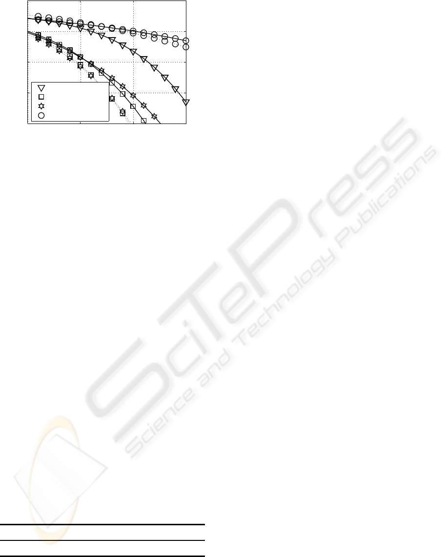
thermore, from Figure 4 we see that unequal PA is
only effective in conjunction with the optimum num-
ber of MIMO layers. Using all MIMO layers, our PA
scheme would assign much of the total transmit power
to the specific symbol positions per MIMO layer hav-
ing the smallest singular values and hence the overall
performance would deteriorate. However, the lowest
BERs can only be achieved by using bit auction pro-
cedures leading to a high signalling overhead (Wong
et al., 1999). Analyzing the probability of choosing a
specific transmission mode by using optimal bitload-
MODULATION-MODE AND POWER ASSIGNMENT IN SVD-ASSISTED BROADBAND MIMO SYSTEMS
87
10 15 20 25
10
−8
10
−6
10
−4
10
−2
10
0
10 ·lg(E
s
/N
0
) (in dB) →
bit-error rate →
(256,0,0, 0) QAM
(16,16,0,0) QAM
(16,4,4, 0) QAM
(4,4, 4, 4) QAM
Figure 4: BER with PA (dotted line) and without PA (solid
line) when using the transmission modes introduced in Ta-
ble 1 and transmitting 8 bit/s/Hz over frequency selective
channels with L
c
= 1.
ing, as depicted in Table 2, it turns out that only an
appropriate number of MIMO layers has to be acti-
vated, e. g., the (16,4, 4,0) QAM configuration. The
results, obtained by using bit auction procedures jus-
tify the choice of fixed transmission modes regardless
of the channel quality as investigated in the contribu-
tion.
6 CONCLUSIONS
Bit and power loading in broadband MIMO systems
were investigated. It turned out, that the choice of
the number of bits per symbol as well as the number
of activated MIMO layer substantially affects the per-
formance of a MIMO system, suggesting that not all
MIMO layers have to be activated in order to achieve
the best BERs. The main goal was to find that spe-
cific combination of the QAM mode and the number
of MIMO layers, which gives the best possible BER
performance at a given fixed bit/s/Hz bandwidth effi-
ciency. The E
s
/N
0
value required by each scheme at
BER 10
−4
was extracted from computer simulations
and the best systems are shown in bold in Table 1.
Table 2: Probability of choosing specific transmission
modes at a fixed data rate by using optimal bitloading
(10·lg(E
s
/N
0
) = 10 dB and L
c
= 1).
mode (16,4,4,0) (16,16,0,0) (64,4,0,0) (4,4,4, 4)
pdf 0.881 0.112 0.007 0
REFERENCES
Ahrens, A. and Lange, C. (2008). Modulation-Mode and
Power Assignment in SVD-equalized MIMO Sys-
tems. Facta Universitatis (Series Electronics and En-
ergetics), 21(2):167–181.
Ahrens, A. and Lange, C. (2009). Modulation-Mode and
Power Assignment in SVD-assisted MIMO Systems
with limited Feedback. In First Asian Conference on
e-Business and Telecommunications (CeBT), pages 1–
18, Changhua City (Taiwan).
Gesbert, D. (2004). Multipath: Curse or Blessing? A Sys-
tem Performance Analysis of MIMO Wireless Sys-
tems. In Proceedings of International Zurich Semi-
nar on Communications (IZS), pages 14–17, Zurich
(Switzerland).
Hanzo, L. and Keller, T. (2006). OFDM and MC-CDMA.
Wiley, New York.
Haykin, S. S. (2002). Adaptive Filter Theory. Prentice Hall,
New Jersey.
Jang, J. and Lee, K. B.(2003). Transmit Power Adaptation
for Multiuser OFDM Systems. IEEE Journal on Se-
lected Areas in Communications, 21(2):171–178.
Krongold, B. S., Ramchandran, K., and Jones, D. L.
(2000). Computationally Efficient Optimal Power Al-
location Algorithms for Multicarrier Communications
Systems. IEEE Transactions on Communications,
48(1):23–27.
K¨uhn, V. (2006). Wireless Communications over MIMO
Channels – Applications to CDMA and Multiple An-
tenna Systems. Wiley, Chichester.
Park, C. S. and Lee, K. B. (2004). Transmit Power Alloca-
tion for BER Performance Improvement in Multicar-
rier Systems. IEEE Transactions on Communications,
52(10):1658–1663.
Proakis, J. G. (2000). Digital Communications. McGraw-
Hill, Boston.
Raleigh, G. G. and Cioffi, J. M. (1998). Spatio-Temporal
Coding for Wirless Communication. IEEE Transac-
tions on Communications, 46(3):357–366.
Raleigh, Gregory G. and Jones, V. K. (1999). Multivariate
Modulation and Coding for Wireless Communication.
IEEE Journal on Selected Areas in Communications,
17(5):851–866.
Wong, C. Y., Cheng, R. S., Letaief, K. B., and Murch, R. D.
(1999). Multiuser OFDM with Adaptive Subcarrier,
Bit, and Power Allocation. IEEE Journal on Selected
Areas in Communications, 17(10):1747–1758.
Zheng, L. and Tse, D. N. T. (2003). Diversity and
Multiplexing: A Fundamental Tradeoff in Multiple-
Antenna Channels. IEEE Transactions on Information
Theory, 49(5):1073–1096.
Zhou, Z. and Vucetic, B. and Dohler, M. and Li, Y.(2005).
MIMO Systems with Adaptive Modulation. IEEE
Transactions on Vehicular Technology, 54(5):1073–
1096.
WINSYS 2009 - International Conference on Wireless Information Networks and Systems
88
