
MODEL AND APPROACHES FOR TENSION OF PARALLEL
STRUCTURES WITH ELASTIC JOINTS FOR
MICRO AND NANO MANIPULATORS
D. Chakarov, K. Kostadinov and T. Tiankov
Institute of Mechanics, Bulgarian Academy of Sciences, Acad. G. Bonchev Str., bl. 4, 1113, Sofia, Bulgaria
Keywords: Piezo-Actuators, Serial-Parallel Micromanipulator, Elastic Joints, Stiffness Model, Preliminary Tension,
Cell Injection.
Abstract: In this paper piezo actuated micromanipulators are considered with serial-parallel structure including elastic
joints. Such structure allows a preliminary tension of the mechanical system in order to eliminate backlashes
and to improve the performance of the piezo-actuators. A kinematics model of a serial-parallel structure for
local micro manipulators is build here. A pseudo rigid body approach is used, where elastic joints are
modelled as revolute joints. A stiffness model is created to estimate the general stiffness of the manipulator
by means of reduction the stiffness of all elastic joints. Two approaches are presented here for preliminary
tension of parallel manipulator structure: - deflection from the initial manipulator state by introducing of a
driving joints motion during the assembly; - preliminary tensioning of the separate elastic joints. The two
approaches considered are experimented on the manipulator for cell injection. The values of the mechanical
parameters obtained by preliminary tension of the manipulator are pointed out.
1 INTRODUCTION
Micro and nano manipulators are mostly used in
biological and microelectronics research, cellular
technology, chemistry and investigation of thin
films, in atomic force microscopes and scanning
tunnelling microscopes.
There are known micromanipulators with piezo
actuators (Fatikow, 1996; Kasper, 1998). Piezo
actuated micromanipulators with parallel structure
are also developed (Lee, 1999). Robots with parallel
structure possess many advantages. Their small
workspace in the case of cell manipulations is not a
disadvantage, since it is enough for the application
considered. Mechanisms with closed kinematic
chains (Ionescu, 2002; Guergov, 2005, Prusak,
2009) are suitable for high-precision tasks in 3D
space. The high accuracy of such mechanical
systems is due to very high structural stiffness.
From the other hand in order piezo-ceramic
structures to be with high stiffness they can be
realized by parallel or a closed structure which has
to be tensed. It is possible to use deformation in
elastic joints or antagonistic redundant actuators to
achieve tension in closed piezo-ceramic structures
with desired degree of freedom (DoF).
Тo predict the displacements of compliant
mechanisms with elastic joints the pseudo-rigid-
body-model is commonly used (Zhang, 2002). As a
rule it models an elastic joint as a revolute joint with
a torsion spring attached. The pseudo-rigid-body
method is effective and it simplifies the model of
compliant mechanisms. To estimate the mechanism
stiffness with elastic joints an analytical model is
created out taking into account compliances of
elastic joints in all axes. The analytical model is
describing the relationship between input and output
displacements of the mechanism, (Pham, 2005) or
computing the stiffness matrix and estimating the
stiffness performances of the robot (Carbone, 2006).
To increase accuracy of the stiffness matrix
identification alternative methodology is developed
using advantages of analytical and numerical
techniques (Pashkevich, 2009). Such analytical
stiffness models of serial-paralel manipulators with
elastic joints are analyzed in order to synthesize
desired stiffness of the robot end-effector (Chakarov,
2004).
The objective of this paper is to create a stiffness
model and to develop approaches for tension of
serial-parallel structures with elastic joints for micro
135
Chakarov D., Kostadinov K. and Tiankov T.
MODEL AND APPROACHES FOR TENSION OF PARALLEL STRUCTURES WITH ELASTIC JOINTS FOR MICRO AND NANO MANIPULATORS.
DOI: 10.5220/0002171101350140
In Proceedings of the 6th International Conference on Informatics in Control, Automation and Robotics (ICINCO 2009), page
ISBN: 978-989-674-000-9
Copyright
c
2009 by SCITEPRESS – Science and Technology Publications, Lda. All rights reserved
and nano manipulators with application in cellular
technology, microelectronics, chemistry etc.
2 KINEMATIC MODEL OF
PARALLEL STRUCTURES
FOR LOCAL MICRO AND
NANO MANIPULATORS
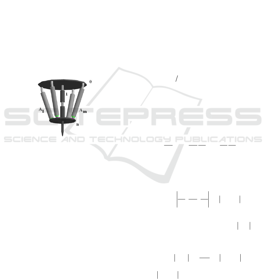
Investigated structures are serial-parallel structures
including basic link 0 and some other links 1, … , n
connected in between in a serial chain. The end-
effector M is situated in the end link n of this chain,
which moves in a ν operation space. The driving
chains A
1
,…, A
m
, with number m, are attached to
the basic link 0 and to the end link n forming parallel
chains [Chakarov, 2007] as it is shown in Fig.1. The
type of the kinematics joints is not shown in Fig.1,
as they can be elastically or kinematically ones.
Figure 1: Generalized kinematic scheme of a serial-
parallel manipulator.
All joints are modelled as kinematic joints with
different number of restrictions, which give 6 DoF
for each drive chain. In this way the number DoF of
the structure is defined by the number DoF of the
serial chain h. Let generalized parameters are
accepted to be the parameters of the relative motions
in all joints - elastic and non-elastic of the structure,
presented by (k x 1) vector
Tl
]q;q[=θ
(1)
Where
q = [q
1
, …., q
h
]
T
(2)
is an (h x 1) vector of the generalized coordinates in
the joints of the main serial chain with h DoF and
Tl
]l;w[q =
(3)
is a (6m x 1) vector of coordinates in the joints of
the actuator chains with number m.
Above
w = [w
1
,..., w
5m
]
T
, (4)
is an (5m x1) vector of coordinates in the passive
joints of the actuator chains, and
l = [l
1
,..., l
m
]
T
, (5)
is an (m x 1) vector of coordinates in the motor
linear joints of the actuator chains.
Let the Cartesian coordinates of the end effector
M are denoted as
[
]
6,X,...,XX
T
ν1
≤ν=
(6)
The relation between the parameters of the basic
serial chain (2) and the parameters of the end
effector (6) is known as a direct problem of the
kinematics of the serial chain. This problem on the
level of displacements and velocities is presented by
the equations
Ψ(q)X
=
and
qJX
&
&
=
(7)
where
[
]
qXJ
∂
∂
=
is the (ν x h) matrix of Jacoby.
In the parallel structure each closed loop implies
the appearance of a connection between the
generalized parameters (1). These connections are
expressed by 6m scalar functions for the structure
including m parallel loops:
1,...,6mi ==θΨ ,0)(
i
.
The differentiation of above equations gives the
relation
M
0
t
q
q
l
H
t
q
q
w
H
td
qd
H
lwq
=
∂
∂
∂
∂
+
∂
∂
∂
∂
+
(8)
The matrix of partial derivations H
q
, H
w
and H
l
with size (6m x h), (6m x 5m) and (6m x m) allows
to produce the summarized matrix of the partial
derivatives
T
T
L;W;E
q
l
;
q
w
;
q
q
D =
∂
∂
∂
∂
∂
∂
=
(9)
where E is unitary (h x h) matrix, W is a (5m x h)
matrix and L is a (m x h) matrix, or
T
H;ED =
.
According to (8) we can reduce the (6m x h)
matrix
q
1
lw
l
T
HH;H
q
q
L;WH
−
−=
∂
∂
== (10)
where
lw
H;H
is a (6m x 6m) invertible matrix.
Using matrix (10) we have the relations between
generalized velocities:
ICINCO 2009 - 6th International Conference on Informatics in Control, Automation and Robotics
136

qHq
l
&&
=
(11)
qWw
&
&
=
(12)
qLl
&
&
=
(13)
The above equations allow determining the
velocities
l
q
&
with dimension 6m as a function of the
generalized velocities
q
&
with dimension equal to the
DoF h of the structure.
When the number of parameters (5) is equal to
the DoF m = h, these parameters can be selected as
independent parameters. In relations (13) L is a (h x
h) matrix and inverse relation is possible:
lLq
1
&
&
−
=
(14)
Equations (7) and (14) allow determining the
velocities of end-effector, while equations (11) and
(14) - the velocities of passive joints, as function of
velocities of linear actuator joins
l
&
:
lJLX
1
&&
−
=
(15)
and
lHLq
1
l
&
&
−
=
(16)
By micromanipulations the above equations give
the relations between small motions of
microactuators Δl, small motions of the end-effector
ΔX and small motions in passive joints
Δq
l
:
lJLX
1
Δ=Δ
−
and
lHLq
1
l
Δ=Δ
−
.
3 STIFFNESS MODEL OF
SERIAL – PARALLEL
STRUCTURES FOR MICRO
AND NANO MANIPULATORS
Denote by P = [P
1
, ... ,Pν ]
T
the (ν x 1) vector
of the external forces and torques applied to the end-
effector, corresponding to Cartesian coordinates (6).
Denote by Q = [Q
1
,..., Q
h
]
T
the (h x 1) vector
of the generalized forces and torques in the joints of
the main chain corresponding to the general
coordinates (2). According to the
principle of virtual
work and equation (7), the
connection between
forces P and Q is as follows:
Q = J
T
P (17)
Denote by
T
qh1qq
F;...;FF =
and
T
m5w1ww
F;...;FF =
(h x 1) and (5m x 1) vectors
of the forces and torques in the elastic joints,
corresponding to coordinates (2) and (4). Denote by
T
lll
m1
F;...;FF = the (m x 1) vector of the driving
forces in the linear joints correspond to the
coordinates (5). Above vectors can be summarized
in the (h + 6m) x 1 vector of forces and torques,
corresponding to the coordinates (1) F= [F
q
; F
w
; F
l
]
T
.
According to the principle of virtual work and
the equation (12), (13) the relation between forces F
and generalized forces Q, using summarized matrix
(9), is as follows:
Q = D
T
F (18)
Q = F
q
+ W
T
F
w
+ L
T
F
l
(19)
Equations (17) and (19) produce
J
T
P = F
q
+ W
T
F
w
+ L
T
F
l
(20)
Differentiation of above equation with respect to
parameters (2) and neglect the second partial
derivatives, gives
L
l
F
LW
w
F
W
q
F
J
X
P
J
lT
w
T
q
T
∂
∂
+
∂
∂
+
∂
∂
∂
∂
=
(21)
Considering micromanipulator structure as a
system with concentrated compliance in the joints
[Chakarov, 2004] gives
1
l
T
w
T
q
T
J]LKLWKWK[JK
−−
++=
(22)
where
XPK
∂
∂
=
is (ν x ν) matrix of the Cartesian
stiffness of the end effector;
qFK
qq
∂∂=
is
diagonal (h x h) matrix of the shaft stiffness in the
joints of the main serial chain;
wFK
ww
∂∂=
is
diagonal (5m x 5m) matrix of the shaft stiffness in
the passive joints of the driving chains;
lFK
l
l
∂∂=
is diagonal (m x m) matrix of the
shaft stiffness in the driving joints.
4 APPROACHES FOR
PRELIMINARY TENSIONING
OF PARALLEL MICRO
MANIPULATORS WITH
ELASTIC JOINTS
A preliminary tensioning of the mechanical
micromanipulation system is necessary in order to
eliminate the backlash and to improve the
MODEL AND APPROACHES FOR TENSION OF PARALLEL STRUCTURES WITH ELASTIC JOINTS FOR MICRO
AND NANO MANIPULATORS
137

performance of the piezo-actuators. When only
joints of class five are used for the modeling the
mechanical system, the number of all joints is equal
to the number k of the generalized system
coordinates. In a case when number m of the driving
joints is equal to the number of DoF h (m=h), then
number of all the remaining joins is (k - h).
The following two approaches can be used for
tensioning of the manipulator:
- deflection from the initial manipulator state by
m = h driving joints motion introduced in the
assembly;
- preliminary tensioning of the separate elastic
joints with number j, (k-h ≥ j ≥ h).
4.1 Tensioning by Means of Deflection
from the Initial State
This can be achieved by means of an assembly
deflection δl in the driving joints, which leads to
deflection in all the system joints according to (14),
(12) and deflection of the end-effector according to
(
7) defined by the equations:
lLq
1
δ=δ
−
(23)
lWLqWw
1
δ=δ=δ
−
(24)
lLJqJX
1
δ=δ=δ
−
(25)
These deflections lead to elastic joints forces
defined by the equations:
lLkqkF
1
qqq
δ=δ=
−
(26)
lWLkwkF
1
www
δ=δ=
−
(27)
where k
q
and k
w
are stiffness matrices of the passive
joints of the basic serial chain and of the driving
chains, respectively. The tensioned elastic system
according to (19) is in a static equilibrium:
Q = F
q
+ W
T
F
w
+ L
T
F
l
= 0 (28)
The diagonal matrices k
q
and k
w
contain non-
zero components, responding to elastic joints and
zero components responding to kinematic joints. The
number of non-zero components j must be bigger or
equal to the DoF j ≥ h in order to achieve full degree
of tension of all the actuators and limbs within the
system. Equation (28) allows definition of the forces
of the driving joints F in number h as a function of
the forces F
q
, F
w
in number j ≥ h
F
l
= -L
-Т
[F
q
+ W
T
F
w
] . (29)
4.2 Tensioning by Deformations in the
Elastic Joints
In the manipulator structure with m driving joints
there are k - m passive joints, which can be elastic.
Because the driving joints m = h, by means of which
the piezo-actuators are modelled are hundreds of
times more rigid then the elastic manipulator joints,
it is accepted that the system has 0 DoF. The
tensioning of the elastic joints does not lead to a
change in the manipulator position, but only in a
change of the internal forces. For the actuator
tensioning, the number of the elastic joints j must be
bigger than the number of the DoF j ≥ h. The
preliminary joint deformations can be defined by the
vectors:
δq
0
= [δq
0
1
, …., δq
0
h
]
T
(30)
δw
0
= [δw
0
1
,..., δw
0
5m
]
T
, (31)
where the components of which corresponding to
non-elastic (kinematic) joints are equal to 0.
The joint stiffnesses are represented by the
diagonal matrices k
q
and k
w,
which contain non-zero
components corresponding to the elastic joints and
zero components connected to the kinematic joints.
The preliminary deflections lead to appearance
of forces in the elastic joints defined by equalities:
0
qq
qkF δ=
(32)
0
ww
wkF δ=
(33)
The driving elastic joints forces are in a static
equilibrium (19):
Q = F
q
+ W
T
F
w
+ L
T
F
l
= 0 (34)
The upper equation defines the links among all
the joint forces and allows the derivation of the
driving joints forces in number h as a function of the
elastic forces in number j≥h
F
l
= -L
-Т
[F
q
+ W
T
F
w
] . (35)
The forces in the driving joints can lead to small
deflections in those joints due to the piezo-actuators
high stiffness. Those deflections by the two
approaches can be defined by the equality:
l
l
0
k
F
l =δ
(36)
where the diagonal matrix k
l
includes the stiffness of
the piezo- actuators, and δl
0
are the deflections in the
driving joints after the system tensioning. Resulting
deflection of the end effector can be received
according to equation (15).
ICINCO 2009 - 6th International Conference on Informatics in Control, Automation and Robotics
138
5 NUMERIC
EXPERIMENTATION OF
TENSIONING APPROACHES
IN ROBOTS FOR CELL
INJECTION
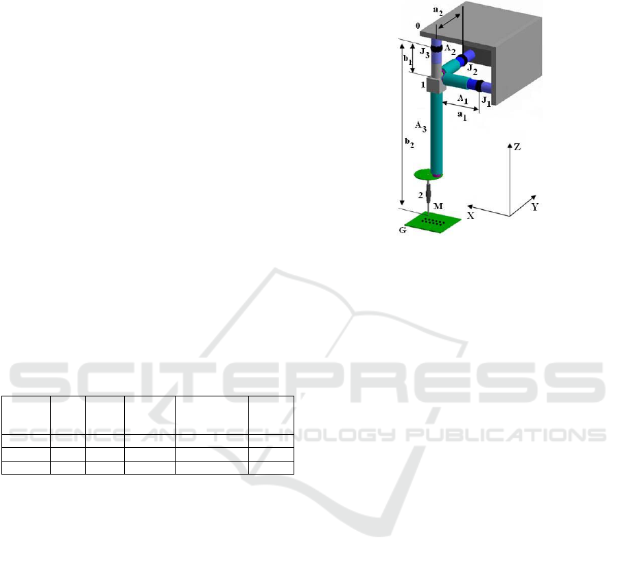
A robot has been designed to perform automatic cell
injection. The cells in the range of 10-30 [
μm] are
preliminary positioned in a matrix G. Local robot
structure has serial-parallel structure with 3 DoF as
shown in Fig.2. Base 0, elastic joint J
3
, manipulator
body 1, actuator А
3,
and working tool 2 with end-
effector M form a serial chain. Actuators А
1
and А
2
are located perpendicularly to the manipulator body
1, and they are linked with the base 0 by means of
elastic joints J
1
and J
2
, thus forming parallel chains.
The actuators are fixed to the body 1 via universal
joints. Parallel structure comprising actuators А
1
and
А
2
perform orientation motions, while the actuator
А
3
performs injection through the pipette 2 attached
to it. The main dimensions of the manipulator are
a
1
=a
2
=0.073[m], b
1
=0.030[m], b
2
=0.180[m] as
shown in Fig.2. Piezoactuators and elastic joints
used have parameters specified in Table 1.
Table 1: Parameters of the elements used.
Elements
T
ravel
[μm]
Resolu-
tion
[nm]
Axial
s
tiffness
[N/μm]
Reduced Axial
stiffness [N/μm]
Angular
stiffness
[N/rad]
А
1,
А
2
30 0.6 27 23.79
А
3
60 1.2 15 13.95
J
2
,J
2
,J
3
200 40
The end effector stiffness and the characteristics
of the preliminary tensing of the parallel structure
can be found. Since the manipulator under
consideration is assembled with a special rectangle
configuration we can easily derive the scalar
equalities for the characteristic components using
the matrix equalities (22), (23), (24), (25), (29).
Software application based on these matrix
equalities is developed using Microsoft Visual
Studio.Net Express Edition and С++.
To find an estimation of a stiffness component
along axis X, the software application substitutes the
respective matrices in equality (22) for
K
w
=40[Nm/rad], J=b
2
, K
l
=23.788[N/m], W=b
1
/a
2
,
K
q
=40[Nm/rad], L=b
1
Performing the respective
calculations, we find for the three additives in (22)
that К
x
=1235+209+660778=0.662 10
6
[N/m].
Similarly, the rest of the end-effector stiffness
components can be found: K
y
= 0.662 10
6
[N/m],
K
z
=13.95[N/m]. As seen, the influence of piezo
actuators to the joint stiffness is hundred times larger
than the rest of the elements.
Figure 2: Microrobot for cell injection.
To apply preliminary tension by the actuator,
following the approach outlined in Sub-paragraph
3.1., actuators А
1
and А
2
in the parallel structure
should deflect by δl
1
and δl
2
, so that the elastic joint
deflection J
3
should not exceed +/-0.5
0
, which is the
admissible arbitrary rotation angle. Thus,
δq
1
=δq
2
=0.008726[rad].
Using scalar equalities corresponding to (23),
(24), (25), (29) as outlined above, we find the
components of the elastic joint deflections and those
of the actuator tension forces – see Table 2.
To attain preliminary tension in the manipulator
as outlined in Sub-paragraph 3.2, the deflections of
the three elastic joints J
1
, J
2
and J
3
should be less than
or equal to the admissible angles of rotation δw
0
11
=
=δw
0
21
=0.008726[rad], δq
0
1
=δq
0
2
=0.008726 [rad].
Considering equality (35) and its scalar forms,
we find the tension forces of actuators A
1
and A
2
, Fl
1
= Fl
2
= -16.42[N]. These forces are larger than the
tension forces found by applying the first approach,
due to the tension of joints J
1
, J
2
that is equal to the
admissible limit.
Both cases of tension yield small
actuator deformations which can be found using
equality (36).
Thus, considering the first case, those
deformations are δl
0
1
= δl
0
2
=-0.572.10
-6
[m], while
for the second case we have δl
0
1
=δl
0
2
=-0.690.10
-6
[m]. The deformations yield deflection of the end
effector with respect to its initial position, equal to
δX
0
=δY
0
= -3.432.10
-6
[m] in the first case and to
δX
0
=δY
0
= -4.142.10
-6
[m] for the second case.
MODEL AND APPROACHES FOR TENSION OF PARALLEL STRUCTURES WITH ELASTIC JOINTS FOR MICRO
AND NANO MANIPULATORS
139
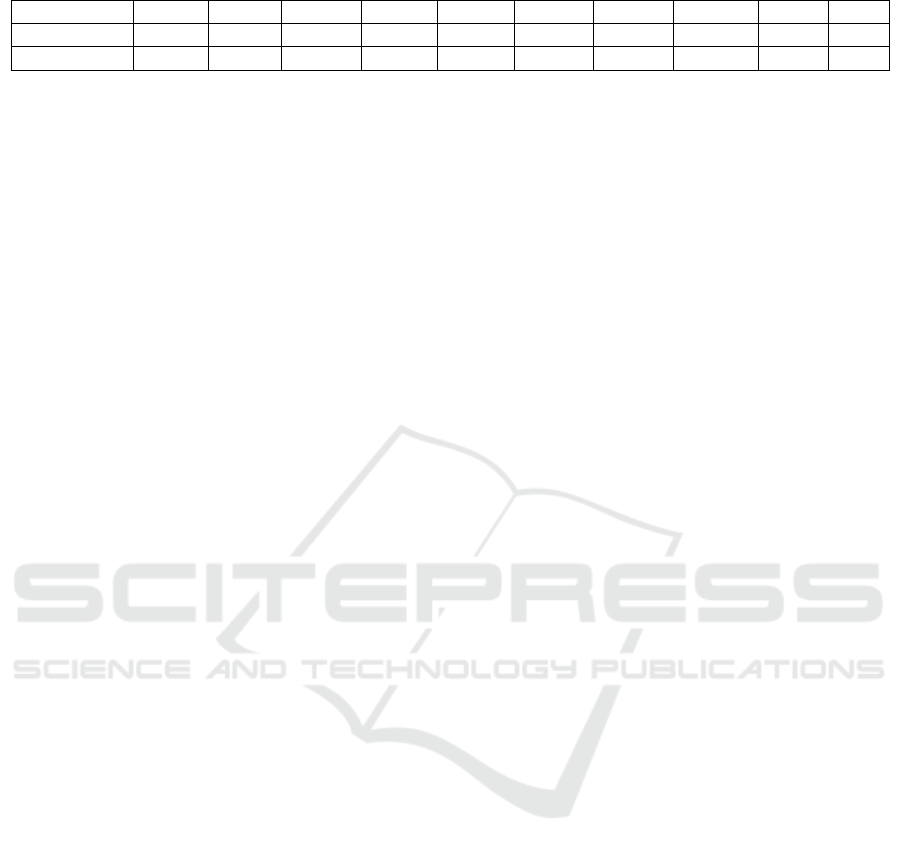
Table 2: Calculated values of the mechanical parameters.
[m] δq
1
[rad] δq
2
[rad] δw
11
[rad] δw
12
[rad] δw
21
[rad] δw
22
[rad] δX [m] δY [m] Fl
1
[N] Fl
2
[N]
δl
1
= 0.263 10
-3
8.72 10
-3
0 0 0 3.589 10
-3
0 1.572.10
-3
0 -13.6 0
δl
2
= 0.263 10
-3
0 8.72 10
-3
3.589 10
-3
0 0 0 0 1.572.10
-3
0 -13.6
6 CONCLUSIONS
Piezo actuated micromanipulators with serial-
parallel structure including elastic joints are subject
of this paper. A kinematic model of the micro
manipulators is build using a pseudo rigid body
method, where elastic joints are modelled as
revolute joints.
A stiffness model is created to estimate the
manipulator stiffness by stiffness reduction of all
elastic joints. In order to eliminate the backlash and
to improve the performance of the piezo-actuators
the parallel structure of the manipulator must be
tensed preliminary. Two approaches are proposed
and presented here for preliminary tension of
parallel manipulator structure:
1. Deflection from the initial manipulator state
by driving joints motion implemented in the
assembly;
2. Preliminary tensioning of separate elastic
joints.
The first approach is easier for realization as the
deviations are performed only in the driving joints.
The elastic joints are tensed to a different degree.
Tensioning of all the elastic joints is realized to
the admissible values by the second approach. Thus,
the maximal values of the tensioning forces are
achieved
The first approach is chosen for the robot
developed for cell injection. The actuators A
1
and A
2
are mounted with deviations related to the values
shown in the first column of Table 2. The robot with
mechanical construction preliminary tensioned
experimented achieves motion along the axes X, Y и
Z as follows: ΔX=ΔY= 180
[μm], ΔZ=60 [μm].
Minimal displacement obtained experimentally is
30[nm]
Further numeric experiments and tests are under
consideration for more stiff elastically joints and
structures with arbitrary location of the actuators.
ACKNOWLEDGEMENTS
This work was funded by the European Commission
through the FP6 Integrated Project HYDROMEL
with contract No. FP6 NMP2-CT-2006-026622, to
which the authors are expressing their
acknowledgements.
REFERENCES
Fatikow, S., Munassypov, R., 1996, An Intelligent
Micromanipulation Cell for Industrial and Biomedical
Applications Based on a Piezoelectric Microrobot, 5
th
Int. Conf. on MicroElectro, Opto, Mechanical Systems
and Components, Berlin, 17-19 Sept., pp. 826-828.
Kasper, R.; Heinemann, W.; Wagner, A., 1998, Modelling
and Control for Piezoelectric Actuators for High
Speed Applications. 4
th
Inl. Conf. on Motion and
Vibration Control, Vol. 1, ETH Zürich, 231-236.
Lee, K., Arjunan, S., 1999, A three-degree-of-freedom
micromotion in-parallel actuated manipulator, IEEE
Trans. on “Robot. and Autom.”, vol. 7, 238-247.
Ionescu Fl., Kostadinov, K., 2002, Piezo actuated micro
robot for micro and nano manipulations, ARA Journal,
Vol. 2000-2002, Nr.25-27, Montréal, 98-103.
Guergov, S., 2005, Multifunctional technological system
with complex functions, reconfigurable structure, high
level of integration and self-organizing elements.
Proc.of V Int. Congress“Computer Science for Design
and Technology”, STANKIN, Moscow, 31-36.
Prusak, D., Tadeusz Uhl, 2009, Novel Type of Hybrid 3-
DOF Micromanipulator with Piezoelectric Actuators -
Mechanical Construction and Simulations, Solid State
Phenomena, Vols. 147-149, pp25 -30.
Zhang, W., Zou, J., Watson, L., Zhao, W., 2002, The
constant- jacobian method for kinematics of a three
DOF planar micro-motion stage, Journ.of Robotic
Systems 19(2). 63–72.
Pham, H., Chen, I., 2005, Stiffness modeling of flexure
parallel mechanism, Precision. Engineering 29, 467–478.
Carbone, G., Lim, Hun-ok, Takanishi, A., Ceccarelli, M.,
2006, Stiffness analysis of biped humanoid robot,
Mechanism and Machine Theory, 41, 17–40.
Pashkevich, А., Chablat, D. ,Wenger, Ph., 2009, Stiffness
analysis of overconstrained parallel manipulators,
Mechanism and Machine Theory, Vol. 44, 966–982.
Chakarov, D., 2004, Study of the Antagonistic Stiffness of
Parallel Manipulators with Actuation Redundancy,
Mechanism and Machine Theory, Vol. 39/6, 583-601.
Chakarov, D., Abed Al-Wahab, M., Kasper, R.,
Kostadinov, K., 2007, Synthesis of tense piezo
structures for lokal mikro & nano manipulations. 8
th
Magdeburg days of mechanical engineering, Oct.10-
11, Magdeburg, pp.173-180.
ICINCO 2009 - 6th International Conference on Informatics in Control, Automation and Robotics
140
