
A PRACTICAL APPROACH FOR COMBINATORIAL FUZZY
LOGIC CONTROL DESIGN
Arturo V. Téllez, Luis A. V. Villa, Herón L. Molina, Oscar N. Camacho and Romeo P. Urbieta
Centro de Investigación en Computación, Instituto Politécnico Nacional
Juan de Dios Batiz Ave. s/n, Nueva Industrial Vallejo, Mexico City, Mexico
Keywords: Fuzzy Logic Controller, Fuzzy Sets Adaptation, Combinatorial Design, FPGA, Fast Prototyping, Hardware.
Abstract: This paper presents the architecture development of a Fuzzy Logic Controller (FLC), using combinatorial
design implemented on a Field Programmable Gate Array (FPGA). This architecture is based on
combinatorial basic modules that enable to increase and improve the entire system performance, by means
of replication technique, which is widely used in computer architecture, and help to fit the particular
application needs. Recent FPGA technology let us use fast combinatorial circuits for complex designs with
parallelism for increasing the FLC performance and it is possible to take it up again as a practical way to
build FLC for any process, approaching the fast prototyping advantages and easing the scaling to increase
the control accuracy.
1 INTRODUCTION
A FLC can be implemented in software easily and
executed in a microprocessor, a microcontroller, or a
general purpose computer. Though software- based
FLC are cheaper and flexible, there are some
difficulties when control systems require high data
processing. The use of FPGA has been profitable
when talking about versatility to make any digital
design by means of costs and design time. In
principle, the implementation of FLC is not based on
the mathematic model of the plant, but this kind of
system is very effective to control a process where
the transfer function is not known, instead the
control action is based on the extern influence and
simple decisions based on a knowledge base
acquired with experience, the same way a human
would do it, exploiting the heuristic ability. There
have been so many FLC implementations since the
first hardware one appeared (Togai, 1986), which
used complex designs with sequential circuits
because of the high hardware resource and delay
time costs about combinatorial design. A large
quantity of FLC architectures, derived from
Computing Architecture. These architectures are
classified by its processing way. There are
sequential, combinatorial (Manzoul, 1992), parallel,
pipelined and mixed models. Some designers prefer
to implement these operations to calculate a
parameter of the FLC every time it is necessary
(Gaona, 2003); this technique is called Runtime
Computation (RTC). But some designs use extern
elements like memories, sometimes called Look Up
Tables (LUT), to calculate FLC parameters by
anticipation; this another technique is called Look
Up Computation (LUC) and represents a good way
to improve the timing (Vasantha, 2005; Singh, 2003;
Deliparaschos, 2005). It is a dare to play with these
architectures and techniques to make a balanced
FLC design, by which it is necessary to change the
way of designing algorithms to describe a FLC.
This paper shows a practical approach of FLC
combinatorial architecture in order to make simple
construction modules and easy upgrading using a
reprogrammable device, FPGA.
Figure 1: Fuzzy Logic Controller.
343
V. TÃl’llez A., A. V. Villa L., L. Molina H., N. Camacho O. and P. Urbieta R.
A PRACTICAL APPROACH FOR COMBINATORIAL FUZZY LOGIC CONTROL DESIGN.
DOI: 10.5220/0002172303430346
In Proceedings of the 6th International Conference on Informatics in Control, Automation and Robotics (ICINCO 2009), page
ISBN: 978-989-8111-99-9
Copyright
c
2009 by SCITEPRESS – Science and Technology Publications, Lda. All rights reserved
2 SYSTEM DESCRIPTION
Assume
as the inputs to the FLC and
as the
outputs. Figure 1 shows a FLC which consists of
three basic stages: Fuzzification, Inference Machine
and Defuzzification. The Fuzzification stage consists
of fuzzy sets. Each fuzzy set converts every crisp
input into several fuzzy values or membership
values. The Inference Machine contains the
behaviour of the FLC and it is built with MIN-
MAX modules. These rules have simple inferences
of the type IF- THEN. Also, the Defuzzification
stage converts these inferred values onto crisp
values, by means of statistical calculations, which
represent the control action over the actuator. The
next steps are required for build a FLC (Tellez,
2008):
1. Establish whatever the designer want to
control and which variables will be related
to get it.
2. Define the number of inputs and outputs of
the FLC based on the last step.
3. Define the number of membership
functions or fuzzy sets for each input and
output based on the last step and define
their shape based on the process
characteristics and operation range of the
FLC (discourse universe).
4. Set the FLC configuration by means of the
fuzzy inference rules according to the
wished operation and based on the expert
knowledge about the process.
5. Build the fuzzifier with simple membership
functions simply by replication
(trapezoidal, triangular, S, Z).
6. Build the inference machine based on step
4, by means of MIN- MAX modules using
the building steps shown in section 2.2.
7. Once inference machine is ready, build the
defuzzification stage by means of
multiplication and division modules using
parallelism.
8. Finally, FLC can be implemented on
FPGA.
For the FLC implementation it was used VHDL,
Xilinx ISE 6.3i, Mentor Graphics Modelsim Xilinx
Edition III 6.0a. It is used Xilinx Spartan 3
XC3S200–5FT256 FPGA Starter Kit. In order to
verify the FLC performance, it was necessary to
make a simulation using the Fuzzy Toolbox of
MATLAB and build a control system with
SIMULINK.
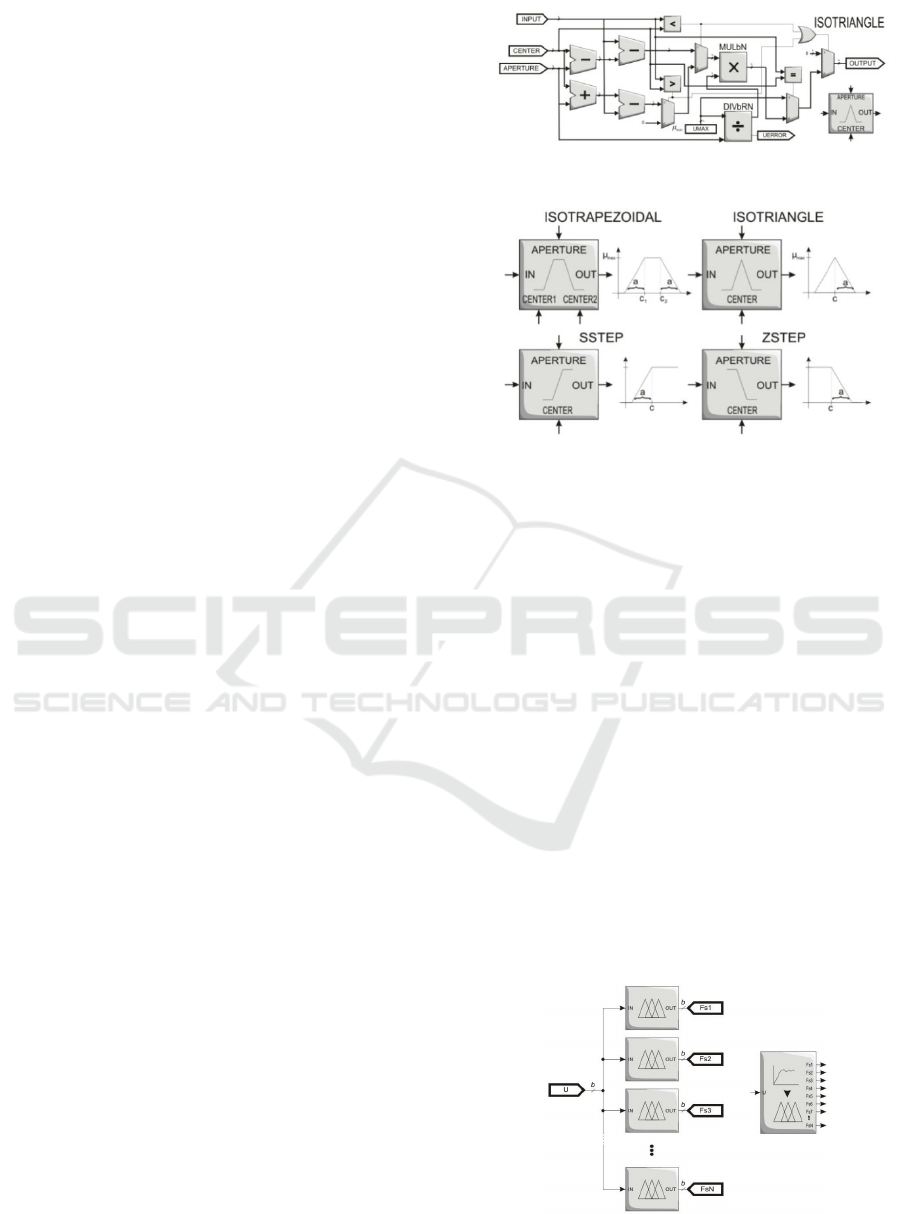
Figure 2: Isosceles triangular membership function shape.
Figure 3: Several hardware suitable membership
functions.
2.1 Fuzzification
The fuzzification stage comprises a set of fuzzifiers
attached to every input variable; each one parallel
from the others and their performance does not
depend on the others either. We assume that all
membership functions shape will be triangular,
trapezoidal, S and Z, because they are the easiest to
implement in hardware as shown in the Figure 2.
These modules convert a crisp digital value into a
membership digital value, according to two
parameters: the CENTER and the APERTURE.
These two parameters of the membership functions
accomplish the RTC technique in order to make the
online adaptation and the FLC tuning.
These functions may have several shapes as
shown in Figure 3 and the interconnection seems
like it follows in Figure 4. Next section describes the
inference machine construction according to a set of
steps using Mamdani operation.
Figure 4: Fuzzifier.
ICINCO 2009 - 6th International Conference on Informatics in Control, Automation and Robotics
344
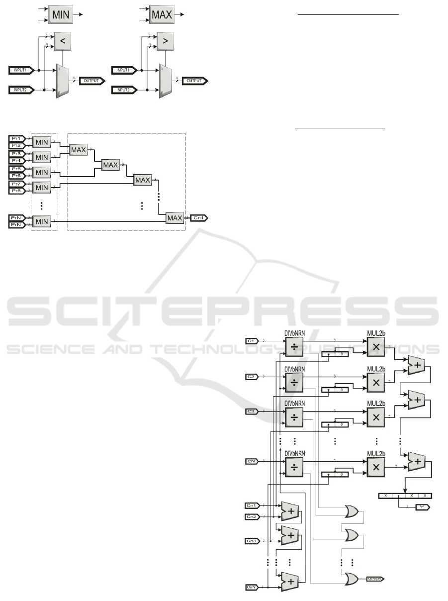
Figure 5: MIN- MAX modules.
Figure 6: Inference machine stage construction.
2.2 Inference Machine
Let us define a premise as the input data involved
with the control, it means that an involved input will
be considered to decide which control action will be
taken. A consequence is a result of the inference, the
output data of inference machine, it means the
decision that FLC will take based on the premises. A
fuzzy rule set is the FLC configuration of the simple
form:
12, … ,
12, … ,
A Mamdani inference machine consists of
MAX-MIN (Figure 5) modules interconnected
according to the fuzzy rule set (Patyra, 1996). A
MAX-MIN structure of an inference machine has
MIN modules in parallel. Unlike the MAX modules
are in cascade, as shown in Figure 6.
2.3 Defuzzification
This stage obtains a crisp output by means of output
fuzzy sets, sometimes called Centroid method. The
calculation of the centroid is made using the
membership values
,
,…,
, obtained from
the inference engine, and the output fuzzy set
centers
. It is often considered as singleton
membership function, because of its computational
simplicity and because this statistical calculation is
independent of the output fuzzy set shapes.
∑
,
,…,
∑
,
,…,
(1)
This defuzzifier needs a division calculation, as
seen in the Equation 1, which results
computationally expensive when trying to divide 2
bits multiplication result numbers, which is not
practical neither cheap computationally. In order to
avoid the multiplication before the division, so
part of Equation 1 was implemented this way:
∑
,
,…,
(2)
Then, the result σ
(Equation 2) is multiplied by
every membership value obtained from the inference
machine. To get this, it was needed to implement a
combinatorial non-restoring division (Oberman,
1997) modified to obtain a fixed point 2b bits
quotient, becauseσ
1, as shown in Figure 7.
3 IMPLEMENTATION AND
VERIFICATION
As example of application, a FLC for a DC servo is
implemented, as mentioned above, in order to verify
the correct performance of the FLC.
Figure 7: Defuzzification stage.
A PRACTICAL APPROACH FOR COMBINATORIAL FUZZY LOGIC CONTROL DESIGN
345

The control system was built in MATLAB Fuzzy
Toolbox first, creating a fuzzy inference system by
software (FIS). As an example, suppose that we
want to implement a 2×1 fuzzy system for a DC
servo, which uses nine rules because it has three
fuzzy sets per input (position error eP: NE, ZE, PE.
position error change velocity cP: NC, ZC, PC) and
output (voltage <volts>- V: NV, ZV, PV), shown in
the Figure 7, which are the following:
IF eP is NE AND cP is NC THEN V is NV
IF eP is NE AND cP is ZC THEN V is NV
IF eP is NE AND cP is PC THEN V is NV
IF eP is ZE AND cP is NC THEN V is NV
IF eP is ZE AND cP is ZC THEN V is ZV
IF eP is ZE AND cP is PC THEN V is PV
IF eP is PE AND cP is NC THEN V is PV
IF eP is PE AND cP is ZC THEN V is PV
IF eP is PE AND cP is PC THEN V is PV
Then, it was provided a test bench which
consists of 25 values and describes several input
situations but due to space it is not explained in this
paper. Also, FLC tuning was made changing the
membership function parameters of inputs and
outputs. Table 1 shows all timing and resources in
FPGA used for every implemented module built for
DC servo FLC example. DC servo FLC needs 84 ns
to make a single inference. Then, its processing data
rate is 11.9 MFLIPS.
4 CONCLUSIONS
FLC architecture was designed using RTC
combinatorial arithmetic modules. In order to get
this, it was supplied to designer a practical approach
for FLC design, using a study case (DC servo).
Those developed modules were implemented in
FPGA and it was possible to verify the FLC
performance compared with the FIS simulated with
MATLAB. We proved that this architecture has the
capability of grow modularly. This modularity may
be approached using a FIS to VHD language
interpreter that simply generates the proper HDL
program, using the basic modules presented in this
paper, regardless the used technology, based on the
MATLAB *.fis configuration file.
ACKNOWLEDGEMENTS
Research supported by the Instituto de Ciencia y
Tecnología ICyTDF funding (award No. PICCT08-
22) and by matching funding by IPN (award No.
SIP/DF/2007/143).
Table 1: FPGA timing and resource results obtained for
DC servo control.
Algorithm Delay (ns) LUT
16 bits non-restoring division 48.50 644
Modified 8 bits non-restoring
division
28.83 208
8 bits restoring division 28.84 124
8 bits multiplication 13.17 36
Isosceles triangle MF
36.70
14.51
251
S-step MF 36.70 249
Z-step MF 36.70 251
Fuzzifier 37.42 755
Defuzzifier 41.49 677
Mamdani inference machine 19.32 242
MIN-MAX operations 9.36 16
FLC 84.01 2689
REFERENCES
Téllez, A., 2008. Fuzzy Logic Controller Architecture
using Combinatorial Logic, Instituto Politécnico
Nacional. Centro de Investigación en Computación.
Mexico City.
Patyra, M. J.; Mlynek, D.M.; “Fuzzy logic:
implementation and applications;” Wiley; 1996.
Oberman, S. F.; Flynn, M. J.; “Division Algorithms and
Implementations;” IEEE Transactions on Computers;
Aug 1997; Vol 46, No. 8; pp. 833–854.
Togai M.; Watanabe H.; “Expert system on a chip: An
engine for real–time approximate reasoning;” IEEE
Expert Syst. Mag., 1986, pp. 55–62, Volume 1.
Vasantha Rani, S.P.J.; Kanagasabapathy, P.; Sathish
Kumar, A.; “Digital Fuzzy Logic Controller using
VHDL;” INDICON, 2005 Annual IEEE, 11–13
December 2005, pp. 463–466.
Singh, S.; Rattan, K.S.; “Implementation of a fuzzy logic
controller on an FPGA using VHDL;” Fuzzy
Information Processing Society, 2003. NAFIPS 2003.
22
nd
International Conference of the North American
24–26 July 2003, pp. 110–115.
Deliparaschos, K.M.; Nenedakis, F.I.; Tzafestas, S.G.; “A
fast digital fuzzy logic controller: FPGA design and
implementation;” Emerging Technologies and Factory
Automation, 2005. ETFA 2005. 10
th
IEEE
Conference, 19–22 September 2005, Volume 1.
Gaona, A.; Olea, D.; Melgarejo, M.; “Sequential Fuzzy
Inference System Based on Distributed Arithmetic;”
Computational Intelligence for Measurement Systems
and Applications, 2003. CIMSA ’03. 2003 IEEE
International Symposium, 29–31 July 2003, pp. 125–
129.
Manzoul, M.A.; Jayabharathi, D.; “Fuzzy Controller on
FPGA Chip;” Fuzzy Systems, 1992., IEEE
International Conference, 8–12 March 1992, pp.
1309–1316.
ICINCO 2009 - 6th International Conference on Informatics in Control, Automation and Robotics
346
