
NEW TYPE OF MULTI-DEGREE-OF-FREEDOM
PIEZOELECTRIC ACTUATORS, BASED ON ACTIVE
KINEMATIC PAIRS
Ramutis Bansevicius, Arunas Lipnickas
Kaunas University of Technology, The Mechatronics Center for Research, Studies and Information
Kestucio 27, Kaunas, Lithuania
Minvydas Ragulskis
Kaunas University of Technology, Research Group for Mathematical and Numerical Analysis of Dynamical Systems
Studentu 50-222, Kaunas, Lithuania
Keywords: Mechatronics, Piezoelectric Actuators, Active Kinematic, Active Bearing, Modelling.
Abstract: New type of multi-degree-of-freedom piezoelectric actuators based on active kinematic pairs is presented.
The contact zone of this type of actuator is formed by two oscillating transducers in a form of rod, plate,
disk or cylinder. Depending on a phase of both transducers in a contact zone and their amplitudes, either
high frequency oblique impacts or periodic change of normal reaction in the contact zone are generated,
leading to continuous motion of one of the links. Schematics of piezoelectric motors, using two active
elements in the contact zone and comprising the number of degrees-of-freedom up to 5 are presented.
Several applications for laser beam deflection and positioning devices in the plane are considered. The
concept of active bearing is introduced; this type of support has no processing datum surface errors.
1 INTRODUCTION
It is worthwhile to introduce the concept of active
kinematic pair in the design of multi-degree-of-
freedom actuators and 3D positioning systems. Such
concept is especially useful in the design of adaptive
positioning systems (Ragulskis, 1988; Bansevicius,
2002a). The characteristic feature of active
kinematic pair is that one or both elements of it are
manufactured from active or smart materials such as
piezoelectric, magnetostrictic or shape memory
materials (Bansevicius, 2002a). Active kinematic
pair can change its kinematic structure or parameters
depending on external conditions or excitation
characteristics (Bansevicius, 2002b). The multi-
functionality of the mechanisms can be achieved
applying direct or inverse piezoelectric effects. In
other words, several different functionalities as
motion generation, measurement of parameters of
motion, control of friction forces in the contact zone
can be implemented into one instrument
(Bansevicius, 2000a; Ko and Kimb, 2006, Chu and
Fan, 2006). Excitation of static or quasi-static
deformations, multi-directional and multi-shape
resonance oscillations, generation of motion in the
contact zone, transformation of oscillations into
continuous motion are just several examples of
application of active kinematic pairs (Bansevicius,
2000b; Bansevicius and Ahmed, 2000ab;
Bansevicius, 2001).
Active kinematic pairs enable:
• Control of the number of degrees-of-freedom of
the kinematic pair by means of friction force
control in the contact zone or generation static
or quasi-static deformations of the element of
the pair;
• Generate forces and moments in the contact
zones;
• To effect additional functions – self-
diagnostics, multi-functionality, adaptively,
self-assembly;
• To implement two levels of degree-of-freedom.
The first level comprises large deflections or
displacements, produced by transformation of
159
Bansevicius R., Lipnickas A. and Ragulskis M. (2009).
NEW TYPE OF MULTI-DEGREE-OF-FREEDOM PIEZOELECTRIC ACTUATORS, BASED ON ACTIVE KINEMATIC PAIRS.
In Proceedings of the 6th International Conference on Informatics in Control, Automation and Robotics - Robotics and Automation, pages 159-164
DOI: 10.5220/0002180401590164
Copyright
c
SciTePress
resonance oscillations of pair’s links into
continuous motion. The second level deals with
small displacements (in nanometre range),
implemented by means of direct piezoelectric
effect and specific sectioning of electrodes.
2 TWO ACTIVE ELEMENTS IN
THE CONTACT ZONE
Applying two active elements in the contact zone of
piezoactuator enables enlargement of the generated
force or torque and transforming oscillations into
continuous motion. High frequency oblique impacts
are generated in the contact zone between two rod
type transducers (Fig. 1). Only longitudinal
resonance oscillations are generated in these rods.
Specific phase differences between the oscillations
in these rods enable variation of the continuous
motion parameters. Zero phase difference generates
direct continuous motion, 180 degree phase
difference enables reverse continuous motion. Phase
difference between 0 and 90 degrees (or between
180 and 270 degrees) changes the normal force
component in the contact zone and helps to tune
dynamical parameters of the whole system with the
rheological parameters of the contact zone.
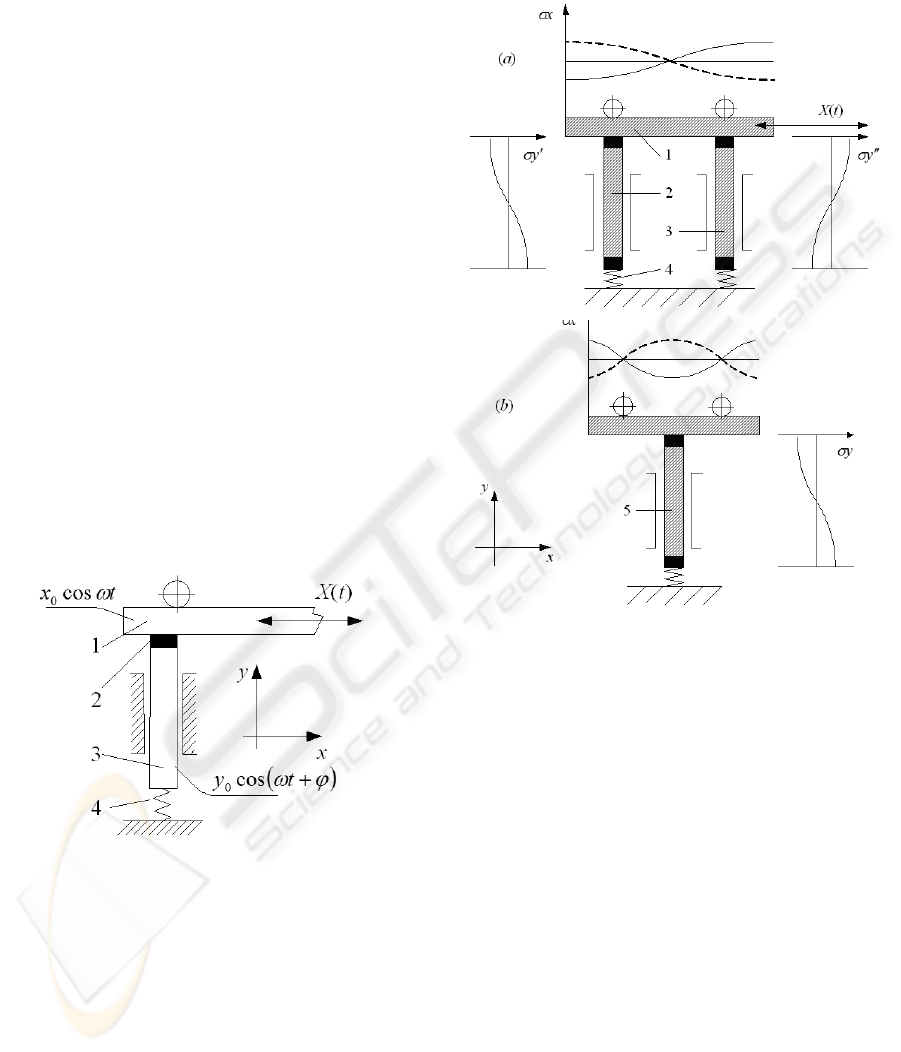
Figure 1: Piezoelectric motor. 1 – the first piezoelectric
transducer (slider); 2 – contact element; 3 – the second
piezoelectric transducer (active support); 4 – spring.
Several schematics of such piezomotors are
presented in Figures 2, 4 and 6. Symmetric scheme
(Fig. 2) enables sufficient increase of the generated
force. Combination of different Eigen modes helps
to achieve larger deflections or displacements of the
sliding element. It must be noted that the reverse
mode is symmetric in all schemes and can be
realised by altering the phase of one of the
transducers by 180 degrees. The scheme presented
in Fig. 2b is implemented in the design of miniature
longitudinal small stroke (2 mm) piezomotor and
well illustrates the technological advantages of such
an approach.
Figure 2: Two cases of piezoelectric motors with two
active elements in the contact zone: (a) - symmetric
scheme; only longitudinal first Eigen shape resonance
vibrations are generated in all actuators (the node is
located in the middle point of the actuator); (b) -
application of different Eigen shapes to increase the
stroke: longitudinal resonance oscillations (second Eigen
shape) are excited in the slider (two nodal points);
longitudinal resonance oscillations (first Eigen shape) are
excited in the supporting actuator (one nodal point).
2.1 Numerical Analysis of Active
Kinematic Pair comprising Two
Active Elements in the Contact
Zone
The active kinematic pair shown in Fig. 1 is
modelled using finite element techniques
(Zienkiewitcz and Taylor, 1991). We used hybrid
elastic body – piezoelectric material finite element
formulations, described in (Ragulskis, 1998). Non-
adaptive uniform finite element meshes were used
for the slider and the active support in order to
secure the best stability and convergence of the
ICINCO 2009 - 6th International Conference on Informatics in Control, Automation and Robotics
160
numerical solution, while an adaptive mesh was
used for the contact element (Fig. 1).
The effect of the pressing spring was assumed as
constant forces, acting to nodes of the outside
surface of the contact element. Limiters for the slider
were modelled as kinematic constrains for the nodes
of the external surface of the slider, permitting
longitudinal but impeding transverse displacements.
Eigen shapes of the slider and the contacting
element were calculated. Then the electrical
excitation of the piezoelectric material was selected
in such a way that the oscillations of the slider and
the active support element would follow their Eigen
shapes (and resonance Eigen frequencies) as close as
possible.
The time step was selected to accommodate
accurate integration of the fifteenth Eigen mode (the
first fifteen Eigen modes were sufficient to represent
complex dynamical processes taking even in the
contact zone). Schematically, the piezoelectric
excitation can be represented as:
()
(
)
()
()
()
(
ϕωδδ
)
ω
δ
δ
+Φ=
Φ=
tyxjiF
tyxjiF
jiAA
jiSS
sin,,
sin,,
(1)
where is a matrix of dynamical forces acting to
the nodes of the slider; are forced acting to the
nodes of the active support; and are first
Eigen shapes of the slider and the active support
(Eigen shape depends from the allocation of
electrodes);
ω
is the resonance frequency (both for
the slider and the active support);
ϕ
is the phase
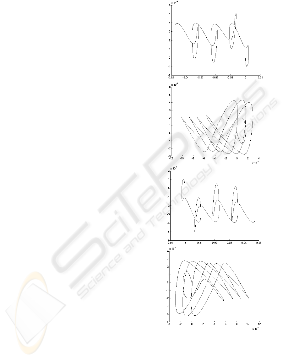
difference of the electric excitation. Numerical
simulations produce a large dataset of results. Only
the trajectory of the middle contact point of the
slider is shown in Fig. 3 in the x-y phase plane in
order to represent main dynamical features.
S
F
A
F
S
Φ
A
Φ
It can be seen that optimal longitudinal motion of
the slider is achieved at
ϕ
= 0, or
ϕ
= 180 (the
reverse mode). Other phase differences result into
chattering mode when the oblique impact energy is
not optimally transferred into the continuous
longitudinal motion of the slider.
(a)
(b)
(c)
(d)
Figure 3: Numerically reconstructed transient dynamical
processes taking place at different phases: (a)
ϕ
= 0; (b)
ϕ
= 90; (c)
ϕ
= 180; (d)
ϕ
= 270 degrees. Note different
scales of x-axis.
NEW TYPE OF MULTI-DEGREE-OF-FREEDOM PIEZOELECTRIC ACTUATORS, BASED ON ACTIVE
KINEMATIC PAIRS
161
3 APPLICATIONS OF MULTI-
DEGREE-OF-FREEDOM
PIEZOELECTRIC ACTUATORS
Piezoelectric actuators based on active kinematic
pairs enable realisation of different types of motion.
Schematic of piezoelectric rotary motor is presented
in Fig. 4. Dynamical processes taking place in the
contact zone are analogous to the basic type
mechanism shown in Fig. 1 and depend on the phase
difference and rheological properties of the contact
surfaces. As in the previous schemes, the resonance
frequencies of the radial oscillations of the disk type
transducer and longitudinal oscillations of the rod
piezotransducer can differ in the range of few
percents. In fact, the range of tolerable differences
depends on the damping in the transducers and in the
whole system in general.
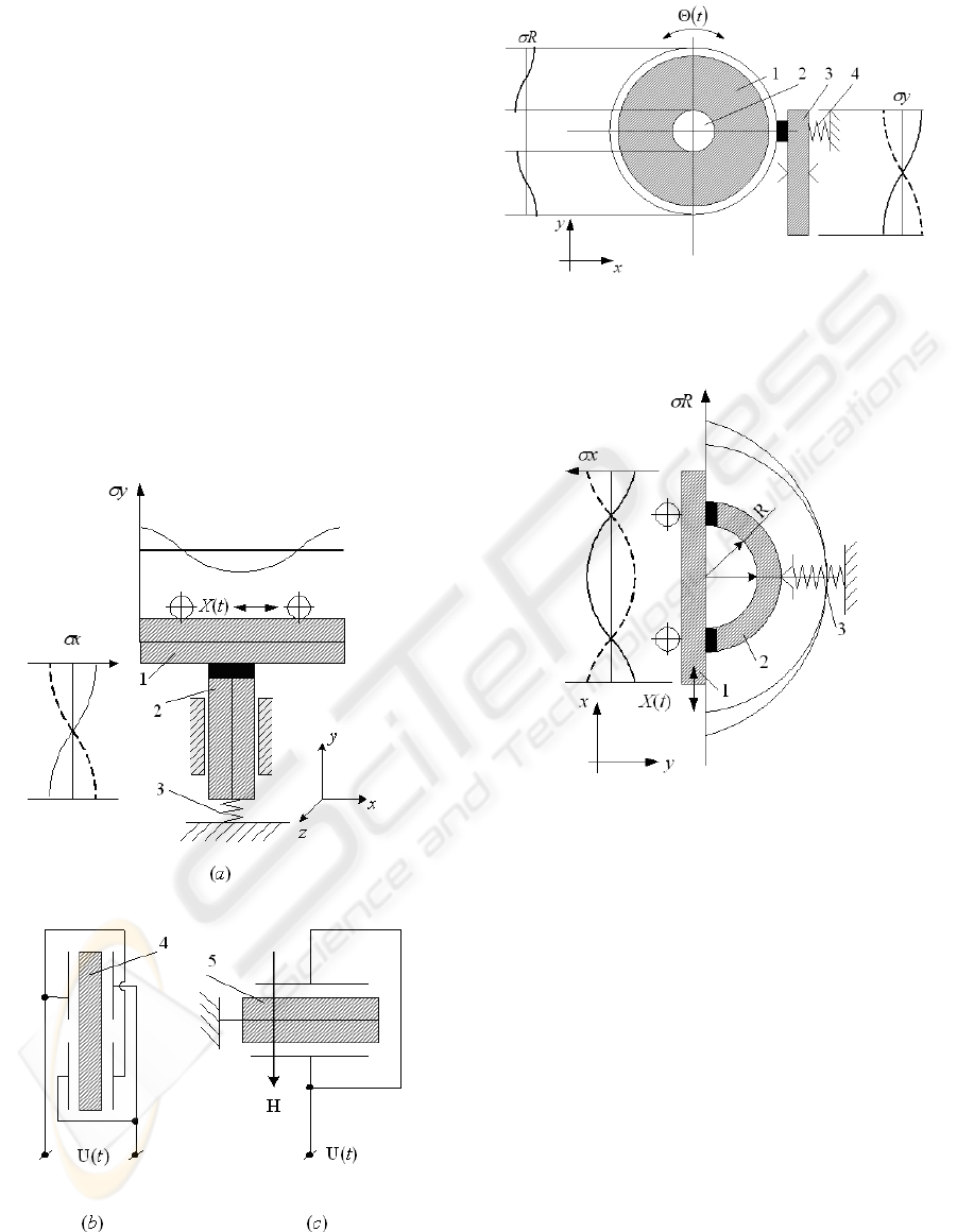
Figure 4: Increasing the velocity by using bimorphic
transducers. 1, 2 – bimorphic piezotransducers; 3 – spring;
4 – schematics of the electrodes; 5 – excitation wiring
diagram; H – poling vector.
Figure 5: Schematics of angular motion piezomotors with
increased torque. 1 – piezoceramic ring; 2 – fixing
element; 3 – rod type piezotransducer; 4 – spring.
Figure 6: Schematic diagram of translational motion
piezomotor analogous to symmetric scheme presented in
Fig. 4.
Two new instrumentation schemes shown in Fig.
7 and Fig. 8 have been implemented practically.
Initial experiments have shown their effectiveness
for implementation small one-degree-of-freedom
positioning systems dedicated for precision
instrumentation. Such schemes can be easily
manufactured using low cost piezotransducers.
Piezomotors with two active elements in the
contact zone can be effectively applied in the design
of optical beam reflection and scanning equipment.
Two cases of such instrumentation are presented in
Fig. 9 and 10. Oblique high frequency impacts are
generated in the contact zone between the cylinder
section and rod type transducer (Fig. 9).
The scheme showed in Fig. 10 enables
implementation of two-degrees-of-freedom motion
of the mirror by electric control of different disk or
plate type piezotransducers’ electrodes.
ICINCO 2009 - 6th International Conference on Informatics in Control, Automation and Robotics
162
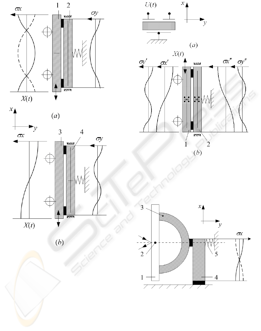
Figure 7: Schematics of translational motion piezomotors
with two active elements in the contact zone. (a): 1 –
piezoceramic transducer (longitudinal resonance second
Eigen shape oscillations; two nodal points); 2 –
piezoceramic bimorphic bending resonance oscillation
transducer (first Eigen shape; two nodal points). (b): 3 –
longitudinal vibration transducer (first Eigen shape; one
nodal point); 4 – bending vibration transducer (second
Eigen shape; three nodal points).
Figure 8: Symmetric translational motion piezomotor with
two active elements in the contact zone. (a): sectioning of
the electrodes; (b): 1, 2 –longitudinal resonance
oscillations (first Eigen shape) and in-plane bending
oscillations (second Eigen shape) are generated in two
identical piezotransducers.
Figure 9: Optical beam reflector. 1 – mirror; 2 – fixing
elements; 3 – piezoceramic sector; 4 – piezoelectric rod,
generating longitudinal resonance first Eigen shape
oscillations.
NEW TYPE OF MULTI-DEGREE-OF-FREEDOM PIEZOELECTRIC ACTUATORS, BASED ON ACTIVE
KINEMATIC PAIRS
163
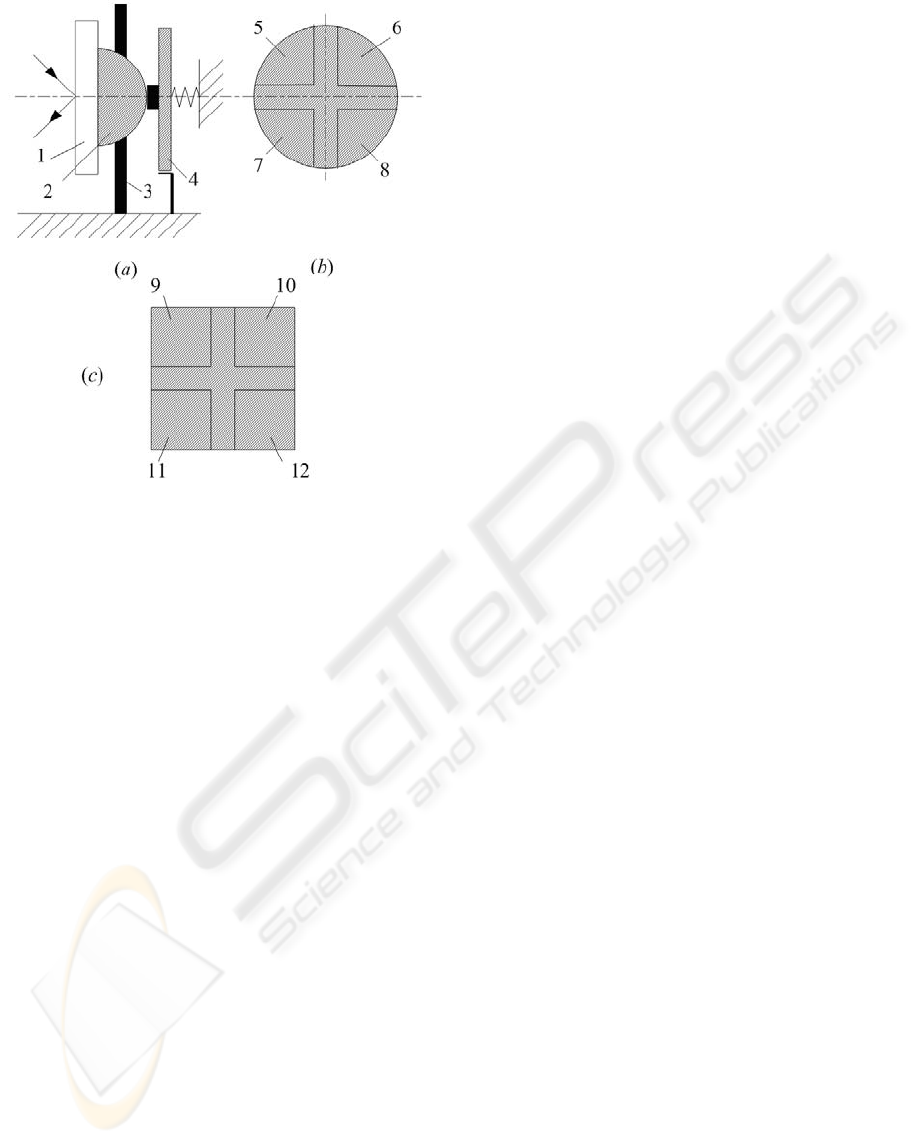
Figure 10: Two-degree-of-freedom optical beam
reflector/scanner. 1 – mirror; 2 – segment of spherical
piezotransducer; 3 – fixing element (scheme is not
specified); 4 – plate type piezotransducer; 5…12 –
sectioned electrodes.
4 CONCLUSIONS
New type of multi-degree-of-freedom piezoelectric
actuators, based on active kinematic pairs, is
presented in this paper. Schematics of piezoelectric
motors, using two active elements in the contact
zone and comprising the number of degrees-of-
freedom up to 5 are presented. Several applications
for laser beam deflection and positioning devices in
the plane are described. The concept of active
bearing is introduced.
The contact zones of these actuators are formed
by oscillating pairs of piezoelectric transducers.
Control of the phase difference between the
transducers enable transformation of oblique impacts
into continuous motion. Such types of actuators are
characterised by high resolution, low time constant,
and are applicable in different areas of precision
mechatronics.
ACKNOWLEDGEMENTS
Research has been financed by Lithuanian State
Science and Studies Foundation (High-Tech
Development program’s research project
PjezoAdapt).
REFERENCES
Ragulskis, K., et al., 1988, Vibromotors for Precision
Microrobots, Hemisphere Publishing Corp., New
York, 310 p.
Bansevicius, R. et al., 2002a, The Mechatronics
Handbook, CRC Press, Boca Raton.
Bansevicius, R., 2002b, Latest trends in the development
of piezoelectric multi-degree-of-freedom actuators/
sensors. Responsive systems for active vibration
control, NATO Science Series, Vol. 85, Kluwer
Academic Publishers, Dordrecht, p.207-238.
Bansevicius, R., et al., B., 2000a, Design and control of
precise robots with active and passive kinematic pairs,
Mechatronics 2000: Proceedings of the 7-th
Mechatronics Forum, Atlanta, Georgia, U.S.A.,
Pergamon, p.10-16.
Ko, H-P., et al., 2006, A novelty in ultrasonic linear motor
using the radial mode of a bimorph, Sensors and
Actuators A 125, p.477–481.
Chu, C-L. and Fan, S-H., 2006, A novel long-travel
piezoelectric-driven linear nanopositioning stage,
Precision Engineering 30, p.85–95.
Bansevicius, R., et al., 2000b, Active error compensation
for precise machines, IMEKO 2000: XVI IMEKO
World Congress Proceedings, Vienna, Vol. 8, p.21-26.
Bansevicius, R. and Ahmed, S., 2000a, Piezoelectric
Active Supports, U.K. Patent 2313982, Patented by
Smart Technology Ltd., U.K..
Bansevicius, R. and Ahmed, S., 2000b, Piezoelectric
Actuators, U.K. Patent 2332090, Patented by Smart
Technology Ltd., U.K..
Bansevicius, R. and Ahmed, S., 2001, Bearings and
Support, USA Patent 62625114B1, Patented by Smart
Technology Ltd., U.K..
Zienkiewicz, O.C. and Taylor, R.L. 1991, Finite Element
Method – Solid and Fluid Mechanics: Dynamics and
Nonlinearity, Vol. 2, McGraw-Hill: New York.
ICINCO 2009 - 6th International Conference on Informatics in Control, Automation and Robotics
164
