
TWO-STAGE ALGORITHM FOR PATH PLANNING PROBLEM
WITH OBSTACLE AVOIDANCE
Mustafa Dogan and Nizami Gasilov
Baskent University, Faculty of Engineering, Eskisehir Yolu 20. km, Baglica, 06810 Ankara, Turkey
Keywords: Path planning, Obstacle avoidance, Graph theory, Dijkstra’s algorithm.
Abstract: The path-planning problem is considered for mobile robot inside environment with motionless circular
obstacles in different sizes. The robot is expected to reach a given target by following the shortest path and
avoiding the obstacles. The two-stage algorithm is proposed to solve the problem numerically. In the first
stage a line-arc based path is found by using geometric techniques. This path cannot be minimal. However,
its length can be used to restrict search space to an ellipse, which contains the minimal path. Thus, the
reduced search space makes the next stage more efficient and endurable for real-time applications. In the
second stage of the algorithm, by discretization of the restricted elliptic region the problem results in finding
the shortest path in a graph and is solved by using the Dijkstra’s algorithm. The proposed two-stage
algorithm is verified with numerical simulations. The results show that the proposed algorithm is successful
for obtaining an optimal solution. The applicability of the proposed algorithm is validated by practical
experiment.
1 INTRODUCTION
Various methods have been proposed for the
solution of obstacle avoidance problem. One of the
real-time methods that has been developed for
navigation of mobile robots is potential field
approach (Connoly et al., 1991; Rimon and
Koditschek, 1992). The main advantage of this
method is on-line efficiency as a result of the
integration of the low-level robot control and path
planning. However, its main disadvantage is that in
some cases it could not escape from local minima
that result in abnormal termination without reaching
the target. Harmonic potential functions (Connoly et
al., 1991) and navigation functions (Rimon and
Koditschek, 1992) are proposed to overcome these
difficulties and in this way obstacle avoidance is
succeeded, but optimal path finding cannot be
achieved. Besides, navigation functions are difficult
to calculate and impossible to be implemented in
real-time, especially for robots that have many
degrees of freedom (Kavraki et al., 1996).
Furthermore, navigation functions should be
differentiable by the definition and therefore, they
can cause problems in piece-wise continuous or
saturated robot control applications (Rimon and
Koditschek, 1992). Nevertheless, potential field
method is improved by the recent advances in both
theoretical and application aspects, e.g. 3-D
extension (Chuang, 1998; Chuang and Ahuja, 1998;
Ren et al., 2006; Cowan, 2007).
Probabilistic roadmap for path planning is just
another alternative method (Kavraki et al., 1996,
1998). This method, in comparison with the previous
ones, can be more reliable and applicable in more
general cases. On the other hand, theoretic analysis
becomes more complex, which is an important
disadvantage of this method.
Some other efficient shortest-path algorithms for
mobile robots are also proposed based on graph
theory approach (Helgason et al., 2001; Liu and
Arimoto, 1992). Finally, dynamic programming
(Hamilton-Jacobi-Bellman) methods are used
extensively as well (Dreyfus, 1965; Moskalenko,
1967, Sundar and Shiller, 1997). For example, in
(Sundar and Shiller, 1997), near-optimal solutions
for the shortest path problem have been obtained by
applying the geometric approach efficiently. The
disadvantage of this method is that it lacks the
minimal path in some cases.
In this research, inspired by the last three
approaches (Helgason et al., 2001; Liu and Arimoto,
1992; Sundar and Shiller, 1997) a new two-stage
optimization algorithm is developed. At the first
stage, near-optimal solution is provided by
165
Dogan M. and Gasilov N. (2009).
TWO-STAGE ALGORITHM FOR PATH PLANNING PROBLEM WITH OBSTACLE AVOIDANCE.
In Proceedings of the 6th International Conference on Informatics in Control, Automation and Robotics - Robotics and Automation, pages 165-170
DOI: 10.5220/0002185001650170
Copyright
c
SciTePress
geometric incremental approach, and this solution is
used to describe the elliptic region that contains the
shortest path. Thus, the optimal solution can be
readily searched after the completion of the first
stage by Dijkstra’s algorithm.
Different from the graph-based heuristic
algorithms, e.g. A* (Dechter and Pearl, 1985; Hart et
al., 1968; Hart et al., 1972; Nilsson, 1980; Bruce
and Veloso, 2006), the proposed method does
guarantee that the selected path is optimal.
Furthermore, A* algorithm can result in the much
longer path than Dijkstra’s one, depending upon
crucial choice of the heuristic function and world
configuration.
The most important novelty of this work is that
the initial search space is reduced a lot in order to
find the shortest path efficiently. Therefore, two
main disadvantages of Dijkstra’s algorithm, namely
large computational burden and difficulty with
following the discrete paths (Helgason et al., 2001),
have been overcome by search space reduction and
greedy path construction approach that explained in
Section 4. These two properties are indispensable in
real-time applications.
2 PROBLEM DEFINITION
Suppose, motionless circular obstacles located in
rectangular domain (search space) are given in finite
number. It is assumed that no obstacle cuts or
touches any other obstacle. The motivating question
behind this research is how point robot can navigate
on the shortest path from a given starting point S to a
given target position F with obstacle avoidance.
Note that, the condition about point robot is not a
restriction for the problem. Let the robot be circular
with radius
ρ
. If we enlarge all obstacles in the
amount of
ρ
radius-wise, then the robot itself can
be considered as point robot.
Also note that, the proposed approach can be
easily extended for the case when other types of
obstacles such as ellipses, convex polygons are
considered together with circles.
Two-stage algorithm is proposed for numeric
solution to the problem. The detailed explanations of
these stages are given in the following sections.
3 INCREMENTAL METHOD
BASED ON GEOMETRY
The method applied at the first stage is incremental
since it is optimal just for one step. The method is
realized by using geometric representations. The
first obstacle on the straight line between the current
position of the object and the target is assumed to be
a single obstacle in each step of the method. In
accordance with this, the tangential path is
determined firstly from the initial point to this
obstacle. Besides, extra obstacles are controlled
whether they intersect the path or not. If not (refer to
Section 3.1), this path is used to reach the obstacle.
Then, the path is followed along the boundary of the
obstacle until the point, where tangent from the
target touches the obstacle. This point becomes the
new starting point for the next step. If there are extra
obstacles across the tangential path that connects the
initial point S and the first obstacle (refer to Section
3.2), then the extra obstacle that is closest to S will
be determined. This extra obstacle is reached along
the tangential path closer to the baseline SF and
avoided by following its boundary. Then, arrival
point is determined as new starting point for next
step. This process will be iterated until no obstacle
on the way to target.
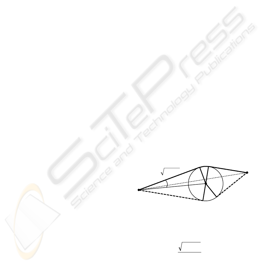
3.1 Single Obstacle Avoidance
Assume that on the path SF, there is only one
circular obstacle with the radius r and centered at C
as represented in Figure 1. Two pairs of tangent
lines from points S and F can be drawn to the circle.
We can choose the ones that have minimum angle
with line SF, i.e. SA
1
and FB
1
in the figure.
Therefore, according to geometrical rules the
shortest path consists of line SA
1
, arc A
1
B
1
and line
B
1
F.
Figure 1: Optimal avoidance of a single obstacle.
In order to calculate coordinates of points A
1
and
A
2
, the following equation can be used:
SCSA
θ
±
−
= P
l
rl
22
Where
SA and SC are vectors;
)/arcsin( lr
=
θ
;
θ
P is the rotation operator about
point S through an angle
θ
. The sign of
θ
corresponds to choosing one of the points A
1
and A
2
.
2
B
C
S
F
r
l
22
rl −
o
o
θ
o
1
B
o
2
A
1
A
ICINCO 2009 - 6th International Conference on Informatics in Control, Automation and Robotics
166
One of them, which is the closest point to baseline
SF, is selected, either A
1
or A
2
.
We can make a significant evaluation for proving
convergence of approximate method based on
geometry. Since circular obstacle centered at
C
crosses the line
SF, we have: rd < (Fig. 2). Hence
.
2
2
2
2
BFSFBFrCF
dCFHFHFSHSF
>⇒=−>
>−=≥+=
According to last inequality, direct distance to
the target decreases by avoiding an obstacle.
Figure 2: Schematic representation to prove that the direct
distance to the target decreases with obstacle avoidance.
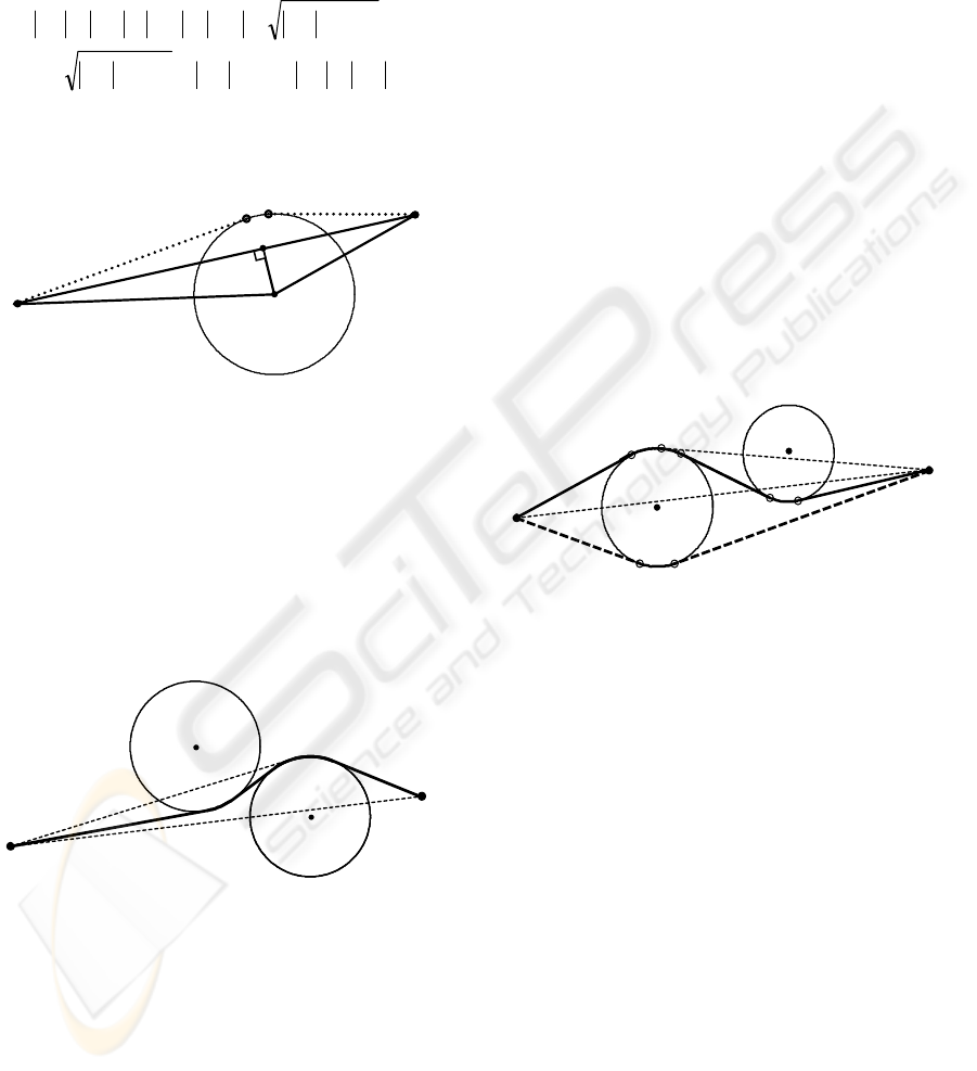
3.2 Extra Obstacle Avoidance
There could be some extra obstacles across the
tangential path SA that is mentioned in Section 3.1.
It is represented in Figure 3 how the path can be
constructed in this case. In Figure 3, the obstacle
centered at
C is ordinary one on the path SF, and the
obstacle centered at E is the extra one.
Figure 3: Avoidance of an extra obstacle.
The algorithm implemented for extra obstacle
avoidance is explained briefly below.
Among extra obstacles crossing tangential path
SA the obstacle that is the closest one to the base
point S is determined, i.e. the obstacle centered at E
in Figure 3. Direction SF will be our reference to
avoid this obstacle. Tangential path
SP close to line
SF is determined. Subsequently, QR, common cross
tangent of obstacles E and C with end point Q close
to
P, is calculated. The obstacle E has been avoided
by following tangent line
SP first, and then arc PQ.
Then the question is considered whether there is any
other extra obstacle on path
QR, or not. If not, then
by following tangent line QR and arc RB the
ordinary obstacle C will be avoided. If there is an
extra obstacle, new iteration on avoidance of extra
obstacle is started with taking
Q as the new initial
point.
Since number of the obstacles is finite, extra
obstacles will be eliminated after finite number of
steps and an ordinary obstacle will be avoided next.
Refer to end of the Section 3.1, the evaluations
prove that direct distance to the target decreases by
avoiding ordinary obstacle. There is finite number of
obstacles by assumption and the distance to the
target diminishes at each step, then approximate
method based on geometry is convergent.
Geometric method implemented at the first stage
of the main algorithm results in near-optimal
solutions. The path obtained through this method
might not be optimal. Such an example is given in
Figure 4.
Figure 4: An example for which the path obtained by the
geometric method is not optimal.
We can see how the method works for this
example below. Circle C
1
is the first ordinary
obstacle across the path
SF. According to Section
3.1 this obstacle will be avoided following tangent
path
SA
1
closer to baseline SF and then arc A
1
B
1
.
Taking B
1
as the new starting point, the next step of
the method will be initiated. Circle
C
2
is determined
as the ordinary obstacle across path
B
1
F. In order to
avoid it, the tangent, which is closer to the baseline
B
1
F, is calculated. This tangent line crosses C
1
.
Thus, in this time the circle
C
1
becomes extra
obstacle when ordinary obstacle
C
2
is avoided. The
procedure described in Section 3.2 is implemented
to avoid the obstacle
C
1
. Since the starting point B
1
lies on C
1
, the step to reach the extra obstacle will be
eliminated. Only arc
B
1
Q is used to avoid C
1
(Here
Q is the end point of QR, common cross tangent of
circles). At the last iteration of the method, by
following tangent line
QR and arc RB, avoidance of
the ordinary obstacle
C
2
will be completed and by
F
S
C
H
d
B
A
C
S
E
R
P
A
B
F
Q
o
o
o
o
o
F
S
2
B
2
A
1
A
1
C
2
C
Q
R
B
1
B
TWO-STAGE ALGORITHM FOR PATH PLANNING PROBLEM WITH OBSTACLE AVOIDANCE
167

tangent path
BF the target will be reached. Thus, the
path calculated on proposed geometric method is
SA
1
QRBF. As it can be easily seen from Figure 4,
this path is longer than the path SA
2
B
2
F, and
consequently, is not optimal.
Thus, in general, solutions obtained through
geometric method are only near-optimal. To find the
optimal path the second stage of algorithm is
applied, which is explained in the next section.
4 OPTIMAL PATH BY
DIJKSTRA’S ALGORITHM
As it is mentioned above, the path obtained at the
first stage might not be the optimal one. However,
its length
*
1
L
gives an upper bound for optimal path
length
*
L such that
*
1
*
LL ≤ .
The feasible region that contains the optimal path
can be reduced with this inequality on purpose.
Let
X be a point on optimal path. Then it can be
claimed that
****
XFSXSF
LLLL +== .
Since the shortest path should be a line segment
with no consideration for obstacles the following
inequalities can be written:
*
SX
LSX ≤ and
*
XF
LXF ≤ . Thus, we get
*
1
LXFSX ≤+ .
Regarding this inequality, sum of distances from
S and F to a point X lying in the feasible region
cannot exceed the value
*
1
L
. Subsequently, the
feasible region is inside the ellipse with focuses at
S
and
F. Hence, based upon the value
*
1
L the feasible
region can be diminished and restricted to an ellipse
.
Thus, the reduced search space makes the second
stage much more efficient and endurable for real-
time applications
.
In this stage, coordinate transformation is applied
such that new origin will be the midpoint
M of the
line segment SF, and the new horizontal axis will be
in the direction of ray MF. In this new coordinate
system, the feasible region can be described simply
as follows:
()
(
)
1//
22
≤+ byax
where
2/
*
1
La = and 2/)(
2
2*
1
SFLb −= . In the
mean time, changing the coordinate system is also
beneficial such that the realizations of the following
steps will be more efficient.
Discretization of the problem is the next step.
For this purpose, a grid with equal squares is created
over the region. The side length of a square, h, is
complied with the minimum distance between
obstacles,
δ
, such that 3/
δ
≤
h . Intersection points
of the grid, or nodes, are assigned as graph vertices.
Thus the analyzed problem can be solved by graph
theory approach. We can define two prohibited cases
such that a) If the vertex N is out of feasible region,
or b) If the square with side length h and centered at
N intersects an obstacle. In both cases, the vertex N
is marked as forbidden to pass. Graph edges can be
constructed in two alternative ways such that:
1) 8-neigborhood vertices around any vertex V,
which is not prohibited, are examined one by one.
The edge is added between the vertex V and the one,
which is permitted to pass.
2) All pairs of vertices (U, V) are to be examined
one by one. If the vertices of a pair (U, V) are not
prohibited and line segment UV does not intersect
any obstacle, the edge with the length |UV| is
constructed between U and V.
At the first alternative, discrete approach is also
used to construct the edges. Therefore, the total
number of edges is minimal and edge structure is
easy to process. In the second alternative, which can
also be characterized as greedy approach, edge
structure is difficult to implement. However, it
provides solution closer to the optimal solution than
the first one does. In simulations, the results of
which are represented in the next section, the second
approach is applied.
Thus, the solution of the problem is reduced only
to find the shortest path from vertex S to vertex F in
the obtained graph. This new problem is solved by
applying Dijkstra’s algorithm (Anderson, 2004).
Furthermore, some improvements have been done
based upon the properties of the problem in order to
make the Dijkstra’s algorithm application more
efficient. For instance, forbidden vertices are not
included to the set of graph vertices. Let
v be the
number of graph vertices. If the first alternative
mentioned above is realized then instead of weight
matrix of size
vv
×
a zero-one (or binary) matrix of
size
v
×
8 is used. Hence, this approach is suitable
for real-time applications. For the second alternative,
as weight matrix is symmetric, then only lower
triangle matrix can be stored at memory.
Note, that in the first alternative the graph is
sparse (number of edges
ve 8~ ). In this case the
complexity of Dijkstra’s algorithm, implemented
with a binary heap, is
)log(~)log( vvOveO .
ICINCO 2009 - 6th International Conference on Informatics in Control, Automation and Robotics
168
5 SIMULATIONS RESULTS
The proposed two-stage algorithm is verified by
many simulations. In simulations the obstacles are
chosen randomly in a rectangular region. The target
position is selected. Then the proposed algorithm is
executed for different starting positions.
Figure 5: Near-optimal (solid lines) and optimal paths
(dashed line) obtained from calculations in presence of 50
obstacles. Thin dashed line represents the boundary of
elliptic feasible region used at the second stage of the
algorithm.
The results of one simulation are represented in
Figure 5. Here we take scene with size of
120120×=×ba (unit length can be assigned
arbitrarily). We randomly generate circles
),,(
ccc
ryx with radius ]8,4[
∈
c
r . If next candidate
circle don’t intersects an existing one, we add this
circle to the list of obstacles. Otherwise the
candidate one is rejected.
The paths that are obtained by the first stage
have been represented with solid-line. For one of the
starting points, (S
2
), optimal path by the second
stage has been shown as dashed-line in Figure 5.
This optimal path has essential differences in
comparison with the result of the first stage (solid-
line starting from S
2
). For other cases (S
1
, S
3
, S
4
), the
optimal paths, obtained at the second stage, have not
been represented for the purpose of clarity of the
figure, since they do not differ a lot from drawn
ones.
For the case with starting point S
2
, the boundary
of feasible region, used at the second stage, is shown
by an ellipse (thin dashed-line) in Figure 5. This
ellipse envelops an area, which is about 1/5 of the
whole search space (rectangle). Since the operation
complexity of Dijkstra’s algorithm is
)(
2
vO and
v
is proportional to covered area, the benefit of
proposed algorithm is about 25 times better than the
algorithm applied to whole region.
It has been verified by simulations that the
proposed algorithm is useful to solve the
optimization problem for obstacle avoidance.
According to obtained results, in some cases only
the first stage of the algorithm can be sufficiently
used, especially considering robotic applications that
require essential time and memory resources.
Although the proposed algorithm works well for
circular obstacles, more efficient approximations for
obstacles can be obtained by implementing the other
convex figures, e.g. rectangles and ellipses.
Therefore, the geometric method can be extended
easily to cover these shapes. Fortunately, the second
stage of the algorithm is independent from the
shapes of obstacles.
6 EXPERIMENTAL RESULTS
Pioneer 3-DX mobile robot, which has embedded
computer with C++ based ARIA (Advanced
Robotics Interface for Applications) software and
wireless communication capability, has been
controlled by remote PC. Driving capabilities of the
robot are 2-wheel drive, plus rear balancing caster
with differential steering.
Figure 6: Experimental setup.
As shown in Figure 6, after extensive image
processing, necessary path planning commands are
produced by the proposed algorithm that all running
at PC, and are transmitted through wireless network
to the robot. Obstacles are chosen as circular shaped
disks. Besides, their positions are selected in
3
S
1
S
2
S
4
S
TWO-STAGE ALGORITHM FOR PATH PLANNING PROBLEM WITH OBSTACLE AVOIDANCE
169

accordance with robot dimensions (swing radius is
32 cm), and minimum inter-distance requirements,
see Section 4.
The first preliminary experiments are done with
two obstacles to evolve the implementation. Finally,
the last experiment is done with five obstacles. After
image processing, the algorithm is implemented in
an efficient way. At the end, the robot followed the
prescribed path successfully as planned beforehand.
For future work, automatic identification and
setting the robot orientation and pose will be an
important achievement, since it took time to set the
right orientation for the robot. Integrating both
stages of the algorithm with image processing to
work in real time while obeying the dynamic
constraints will complete this research project.
7 CONCLUSIONS
Optimization problem for obstacle avoidance on the
plane has been investigated. Two-stage algorithm
has been proposed for solution to the problem and
tested successfully with experiments. In the first
stage, near-optimal solution is obtained through
geometric approach. Using this solution, the feasible
region is restricted to an ellipse. At the second stage
the problem is reformulated as the shortest path
problem in graph, and optimal solution is found by
applying Dijkstra’s algorithm in the reduced search
space. Consequently, two main contributions of this
research come out clearly at the last stage. The first
one, the solution is optimal, and the second one, it is
obtained through an efficient way with a significant
reduction of search space. Simulation results have
proved that the two-stage algorithm complies with
theory and produces accurate solutions.
REFERENCES
Connoly, C. I., Burns, J. B., and Weiss, R., 1991. Path
planning using Laplace’s equation. Proc. IEEE Int.
Conf. Robot. Automat., vol. 1, pp. 2102-2106.
Rimon, E., and Koditschek, D. E., 1992. Exact robot
navigation using artificial potential functions. IEEE
Transactions on Robotics and Automation, vol. 8, pp.
501-518.
Kavraki, L. E., Kolountzakis, M. L., and Latombe, J. C.,
1998. Analysis of probabilistic roadmaps for path
planning. IEEE Transactions on Robotics and
Automation, vol. 14, no. 1, pp. 166-171
Kavraki, L. E., Svestka, P., Latombe, J. C., and Overmars,
M. H., 1996. Probabilistic roadmaps for path planning
in high-dimensional configuration spaces. IEEE
Transactions on Robotics and Automation, vol. 12, no.
4, 566-580.
Helgason, R. V., Kennington, J. L., and Lewis, K. R.,
2001. Cruise missile mission planning: a heuristic
algorithm for automatic path generation, Journal of
Heuristics, Kluwer Academic Publishers, vol. 7, pp.
473-494.
Liu, Y. H., and Arimoto, S., 1992. Path planning using a
tangent graph for mobile robots among polygonal and
curved obstacles. Int. J. Robot. Res., vol. 11, no. 4, pp.
376-382.
Dreyfus, S., 1965. Dynamic Programming and the Calculus
of Variations. New York, London: Academic.
Moskalenko, A. I., 1967. Bellman equations for optimal
processes with constraints on the phase coordinates.
Autom. Remote Cont. (Translation of Avtomatika i
Telemekhanika), vol. 4, pp. 1853-1864.
Sundar, S., and Shiller, Z., 1997. Optimal obstacle
avoidance based on the Hamilton-Jacobi-Bellman
equation. IEEE Transactions on Robotics and
Automation, vol. 13, no. 2, pp. 305-310.
Anderson, J. A., 2004. Discrete Mathematics with
Combinatorics, 2nd Ed. Prentice Hall.
Dechter, R., and Pearl, J., 1985. Generalized best-first
search strategies and the optimality of A*. Journal of
the ACM
, vol. 32, pp. 505 – 536.
Hart, P. E., Nilsson, N. J., and Raphael, B., 1968. A
formal basis for the heuristic determination of
minimum cost paths. IEEE Transactions on Systems
Science and Cybernetics, vol. SSC-4, no. 2, pp. 100–107.
Hart, P. E., Nilsson, N. J., and Raphael, B., 1972.
Correction to a formal basis for the heuristic
determination of minimum cost paths. SIGART
Newsletter, no. 37, pp. 28-29.
Nilsson, N. J., 1980. Principles of artificial intelligence.
Palo Alto: Tioga.
Bruce, J. R., and Veloso, M. M., 2006. Safe multi-robot
navigation within dynamic constraints. Proceedings of
the IEEE, vol. 94, no. 7, pp. 1398-1411.
Chuang, J.-H., 1998. Potential-based modeling of three-
dimensional workspace for obstacle avoidance. IEEE
Transactions on Robotics and Automation, vol. 14, no.
5, pp. 778-785.
Chuang, J.-H., and Ahuja, N., 1998. An analytically
tractable potential field model of free space and its
application in obstacle avoidance. IEEE Transactions
on Systems, Man, and Cybernetics - Part B:
Cybernetics, vol. 28, no. 5, pp. 729-736.
Ren, J., McIsaac, K. A., and Patel, R. V., 2006. Modified
Newton’s method applied to potential field-based
navigation for mobile robots. IEEE Transactions on
Robotics, vol. 22, no. 2, pp. 384-391.
Cowan, N. J., 2007. Navigation functions on cross product
spaces. IEEE Transactions on Automatic Control, vol.
52, no. 7, pp. 1297-1302.
ICINCO 2009 - 6th International Conference on Informatics in Control, Automation and Robotics
170
