
USING SYNCHRONIZED LIGHTWEIGHT STATE OBSERVERS
TO MINIMISE WIRELESS SENSOR RESOURCE UTILISATION
David Lowe, Steve Murray and Xiaoying Kong
Centre for Real-time Information Networks, University of Technology
Sydney, PO Box 123 Broadway NSW 2007, Australia
Keywords: Wireless Sensor Networks, State Observers, Control, Optimisation.
Abstract: A major trend in the evolution of the Web is the rapidly growing numbers of web-enabled sensors which
provide a rich ability to monitor and control our physical environment. The devices are often cheap,
lightweight, rapidly deployed and densely interconnected. The current dominant models of Web-based data
monitoring are not well-adapted to the operational needs of these devices, particularly in terms of resource
utilization. In this paper we describe an approach to the optimization of the resources utilized by these
devices based on the use of synchronized state-observers. By embedding state observers with a minimized
footprint into both the sensors and the monitoring Web client, we show that it is possible to minimize the
utilization of limited sensor resources such as power and bandwidth, and hence to improve the performance
and potential applications of these devices.
1 INTRODUCTION
One of the key future directions for the evolution of
the Web is a growing integration of real-time
embedded devices into the Web infrastructure,
facilitating the monitoring and control of the
physical environment. This functionality is strongly
supported by the increasing availability of cheap,
small, but powerful sensors and actuators.
There is increasing attention on the mechanisms
for “Web-enabling” these devices, as well as the
development of rich applications that leverage the
real-world data which becomes available. Indeed the
related concept of a Sensor Web is now well
established (Delin, 2002), with a considerable body
of literature on the architecture and protocols for
managing the devices and the resultant real-time
data streams, though the integration of the
SensorWeb with the World Wide Web is less well
developed.
The sensor devices however often have a number
of performance and operational constraints which
may often conflict with current approaches to the
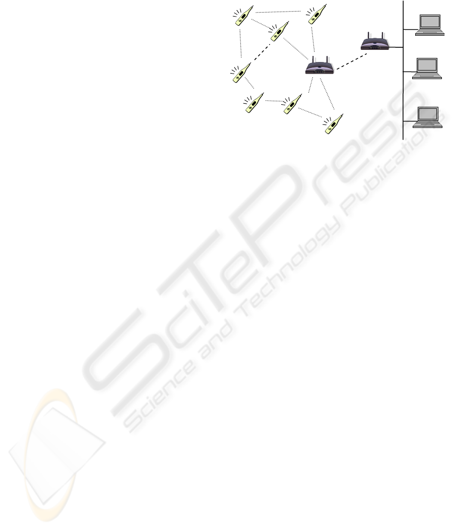
design of Web applications. To illustrate this
consider, for example, a simplified application
involving the embedding of a network of wireless
moisture sensors into a residential garden. The
application then makes available across the Web a
map of the state of the garden (see Figure 1 for a
simplified diagram of a representative architecture).
A typical design of the Web interface for an
interactive application such as this might be to
implement an AJAX-based application with the Web
client pulling content from the network of sensors
(via the data aggregator) as needed by the user.
Whilst this approach provides a rich user experience,
it places requirements on the wireless sensor
network that may lead to suboptimal performance.
In this scenario the communications radio in the
sensors would be required to remain active, in order
to respond to requests for content – leading to
unnecessarily excessive power usage. A simple
improvement would be to allow the sensors to
periodically push content to the content aggregator
node, which then caches the data and responds to
client requests. Even this approach however means
that data communications will be occurring when
they are not necessarily required.
The above scenario is typical of numerous
applications involving embedded devices –
particularly wireless sensor networks (WSNs). The
sensor devices are designed to be extremely low
power, thereby enabling them to operate for
considerable periods (often years) off a single
battery cell. This low power usage is achieved
through having the sensors operate on a very low
5
Lowe D., Murray S. and Kong X. (2009).
USING SYNCHRONIZED LIGHTWEIGHT STATE OBSERVERS TO MINIMISE WIRELESS SENSOR RESOURCE UTILISATION.
In Proceedings of the International Conference on Wireless Information Networks and Systems, pages 5-12
DOI: 10.5220/0002187300050012
Copyright
c
SciTePress
duty cycle, where they spend most of the time in an
extremely low-power “sleep” mode, only waking
periodically to take a sensor reading (and transmit it
if necessary). This makes it infeasible to rely on a
design which requires them to respond to content
requests.
In this paper we consider an architecture based
on synchronized state observers that addresses these
issues and facilitates the optimization of resource
usage in web-enabled sensor networks. In the
following section we describe related work,
considering in particular both the growing trend to
embed sensors directly into the Web infrastructure,
as well as approaches to data monitoring
optimization through the use of a classical technique
from control theory – state observers.
In section 3 we provide an overview of our
proposed architecture, and describe how it addresses
the design constraints. In section 4 we then outline a
prototype evaluation that demonstrates the
performance gains that can be achieved through our
proposed approach. Finally, in section 5, we
consider the implications of this approach and
outline directions for future work.
2 BACKGROUND
2.1 Integrating Sensors into the Web
Improvements in sensor hardware, communications,
and electronics miniaturization have led to a
growing availability of cheap, small, and
functionally rich sensors. As these sensors are
combined with wireless and/or mobile
communications and embedded software, it has
become increasingly possible to connect these
devices either directly into the Web infrastructure, or
to make their data available on the Web through
appropriate gateways. By embedding these devices
into the physical world, and making the resultant
environmental data available on the Internet, a
diverse range of monitoring and control applications
become possible. The result can be a network that is
often referred to as a Sensor Web: “The Sensor Web
is to sensors what the Internet is to computers, with
different platforms and operating systems
communicating via a set of shared, robust
protocols.” (Delin, 2002).
The information provided by sensors can be
incredibly diverse: location, speed, vibration,
temperature, humidity, light, sound, pollutants, etc.
This information, in turn, enables extremely rich
monitoring and control applications, many of which
however only become feasible when the sensors are
small and cheap – which in turn places constraints
on the resources available to the sensors.
Zigbee
Network
WiFi
Network
Internet
Sensors
WebServer
WebClient
Data
A
ggregato
r
Figure 1: Representative architecture of a typical Web-
enabled wireless sensor network.
As an example, consider the following scenario:
a building incorporates a network of temperature and
humidity sensors to support monitoring of the
building environment. To enable them to be rapidly
and cheaply deployed, without requiring cabling,
they are designed as a Zigbee wireless mesh network
("The Zigbee Alliance," 2008) with each sensor
node being battery powered. A significant design
objective on the sensor modules is therefore to
minimize their power utilization in order to
maximize their battery life. As an example, a Zigbee
module might use as little as 1 µA when in deep
sleep, 10 mA when operating, and 40 mA when
transmitting or receiving data. A typical scenario
would have each set of samples requiring the
module to be awake for 5ms and transmitting for
1ms. If it sampled continuously, a standard high-
performance Lithium “coin” battery would last
approximately 50 hours. Conversely, transmitting a
data sample only every 10 seconds, and sleeping the
remainder of the time would give a 1:2000 duty
cycle and an operating life of over 10 years
(ignoring shelf-life characteristics of the battery,
which can vary enormously, from less than a year to
>> 10 years, depending on the environment and the
battery type). Note that other factors, such as the
requirements for data routing, will moderate these
extreme examples somewhat.
Power minimization in turn requires the module
to minimize the time in which it is operational.
Similar resource constraints exist in terms of
minimization of communication bandwidth, CPU
cycles, and other resources.
WINSYS 2009 - International Conference on Wireless Information Networks and Systems
6
2.2 Sensor Network Architectures
Research on the design of architectures which
leverage sensor network technologies has considered
both the architecture of the individual sensors and
the broader network architecture. In terms of the
former, considerable attention has been given to
aspects such as minimization of the software
footprint of the sensor module, optimization of the
sensor design, development of low-power devices,
etc. (Polastre, Hill, & Culler, 2004).
In terms of the broader architecture of sensor
networks, considerable effort has gone into
designing communication topologies and protocols
that are both robust (e.g., self-healing routing) and
minimize power and bandwidth overheads
(Krishnamachari, Estrin, & Wicker, 2002). By
adapting the routing topologies it is possible to
obtain significant performance improvements.
Consider, for example, approaches such as data-
centric routing (Krishnamachari et al., 2002) (which
uses in-network aggregation of data flows) and
dynamic adaptation of sensor sampling rates
(Ganesan, Ratnasamy, Wang, & Estrin, 2004;
Polastre et al., 2004), which are used to improve
performance, minimize network traffic, and reduce
energy consumption.
Whilst these aspects are important, they have
typically been developed without a clear
consideration of the specific characteristics of the
design of the applications which will often be used
to leverage the data. For example, where the data is
used within a Web-based application then one of the
key aspects is consideration of the nature of
interactivity in Rich Web Applications, and in
particular the use of technologies such as AJAX,
Flex and Silverlight to pull content to the Web client
as needed in response to user interactions.
The integration of Sensor networks into Rich
Web Applications is typically done through
continuous collection of the sensor data into a
central repository (whether or not it happens to be
needed at that time) and then either pulling the
content to the browser or streaming it from the
server. In either case, it means that data is collected
from the sensors which may not be needed at a
particular point in time (with the associated wastage
of sensor module resources).
Some work on middleware for sensor networks
can assist in this area. Approaches to lightweight
publish-subscribe models (see, for example (Costa,
Picco, & Rossetto, 2005; Gaynor, Moulton, &
Welsh, 2004; Huang & Garcia-Molina, 2004)) can
provide a mechanism for retrieving sensor content to
the Web server, and then to the browser, only when
the sensor data is changed (or, rather, when the
sensor node determines that the data warrants
publishing). Whilst this is an improvement it still
neglects the interplay between client and server (and
ultimately sensor). For example, the level of
information granularity – both spatial and temporal –
that is relevant to a particular client session will
change over time, and will influence the information
that needs to be published by the sensor.
We believe that one of way of addressing this
problem is through the use of concepts from
classical control theory, and in particular the use of
distributed synchronized state observers.
G(z)
G
Est
(z)
L
(
z
)
A
ctualSystem
ModeledSystem
ObserverCompensato
r
u(k)input
y(k)
Plantoutput
x
O
(k)
Observedstate
x
(k)
Plantstate
(notobservable)
‐
+
+
+
y
O
(k)
Observeroutput
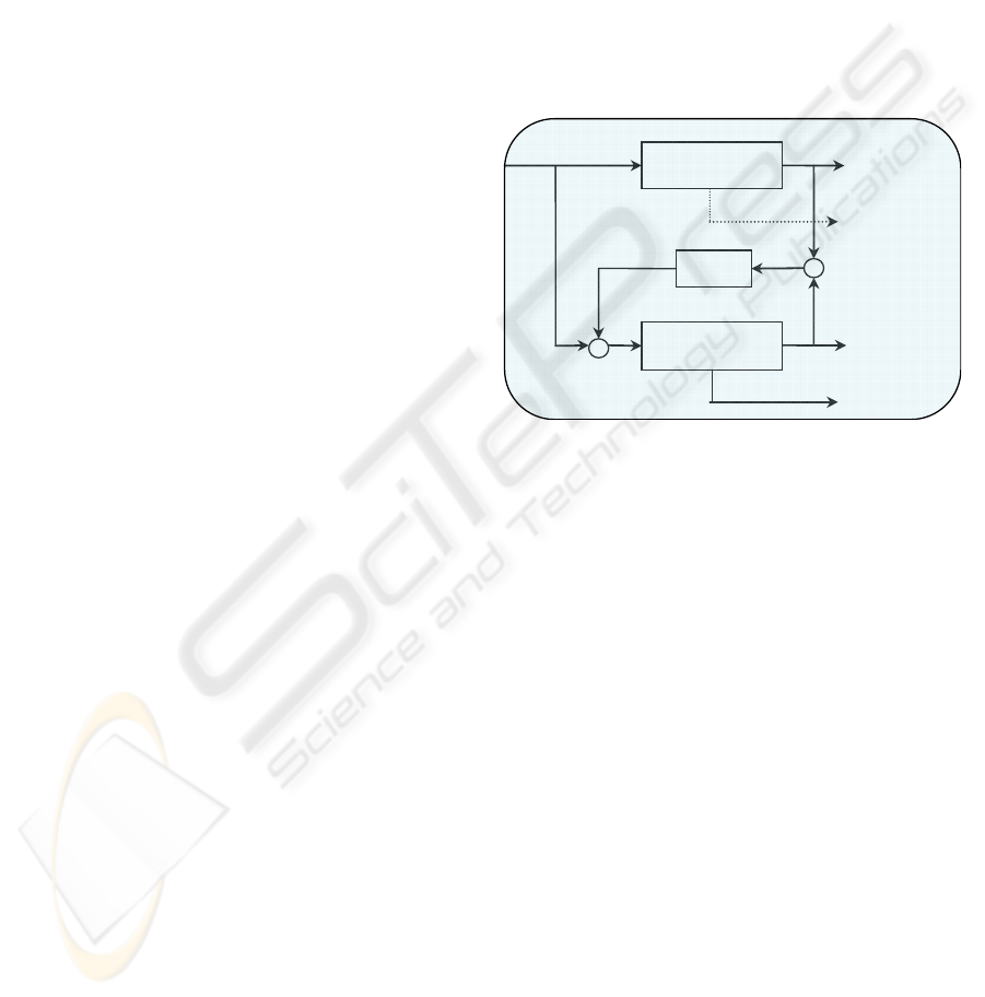
Figure 2: General form of a Luenberger observer.
2.3 State Observers
In classical control theory, we manipulate the inputs
to a system being controlled in order to achieve
system output behaviours that meet performance
requirements. Appropriate modeling allows us to
design controllers which use the error between a
desired system output and the actual output to
generate the system input. This is straightforward
when the system outputs can be reliably measured
(and if the system behaviour is readily modeled –
particularly if the behaviour is linear, though there
are sophisticated techniques for dealing with non-
linear systems). However in many cases some of the
system outputs cannot be directly observed or
accurately measured. (This may be for a range of
reasons – the output variables may be of a form that
is not easy to measure, they may be inaccessible, or
the sensors may themselves introduce errors). In
these cases, one solution is to use a state observer. A
state observer is a model of a real system that gives
us access to an estimate of the internal state of the
system. As shown in Figure 2, with a Luenberger
Observer (Ellis, 2002), the observable outputs of the
physical system are compared to the equivalent
USING SYNCHRONIZED LIGHTWEIGHT STATE OBSERVERS TO MINIMISE WIRELESS SENSOR RESOURCE
UTILISATION
7
outputs from the state observer and used to correct
any errors in the observer using a compensator.
Traditionally state observers have been used to gain
access to estimates of the variables which determine
the state of the system, when these variables cannot
be directly accessed (in Figure 2, we would use x
o
(k)
in our system control, rather than x(k), which cannot
be directly accessed). It is, however, equally
applicable to use estimates, when gaining access to
the actual system variables is inappropriate due to
resource requirements, as may be the case with
sensor networks.
We could use this concept by implementing a
state observer in the Web Server, and which
provides data to the Web clients as requested, but
this raises questions of maintaining the accuracy of
the observer. To address this, we can use data from
the sensors as input to the observer compensator,
however this compensation may often not be
necessary (when the observer is accurately tracking
the real system state and hence does not require
correction) and is therefore a waste of sensor
resources.
We therefore propose an architecture which
utilizes synchronized distributed observers, so that
each sensor includes an embedded copy of the
observer, and can hence determine locally on the
sensor if the observer is deviating and requires
correction. The sensors therefore only provide data
when it is required to keep the observer
synchronized. More simplistic versions of this
approach have been used previously. For example,
numerous approaches have adopted variations of
using constant sampling rates in the sensors, but
only transmitting sensor data when the change
exceeds some threshold (a form of adaptive delta
modulation – see, (Ishwar, Kumar, & Ramchandran,
2003; Li & Fang, 2007)). A state observer however
has the potential to allow a much more intelligent
variation of the transmission thresholds based on a
system model.
3 A WEB-ENABLED SENSOR
OBSERVER
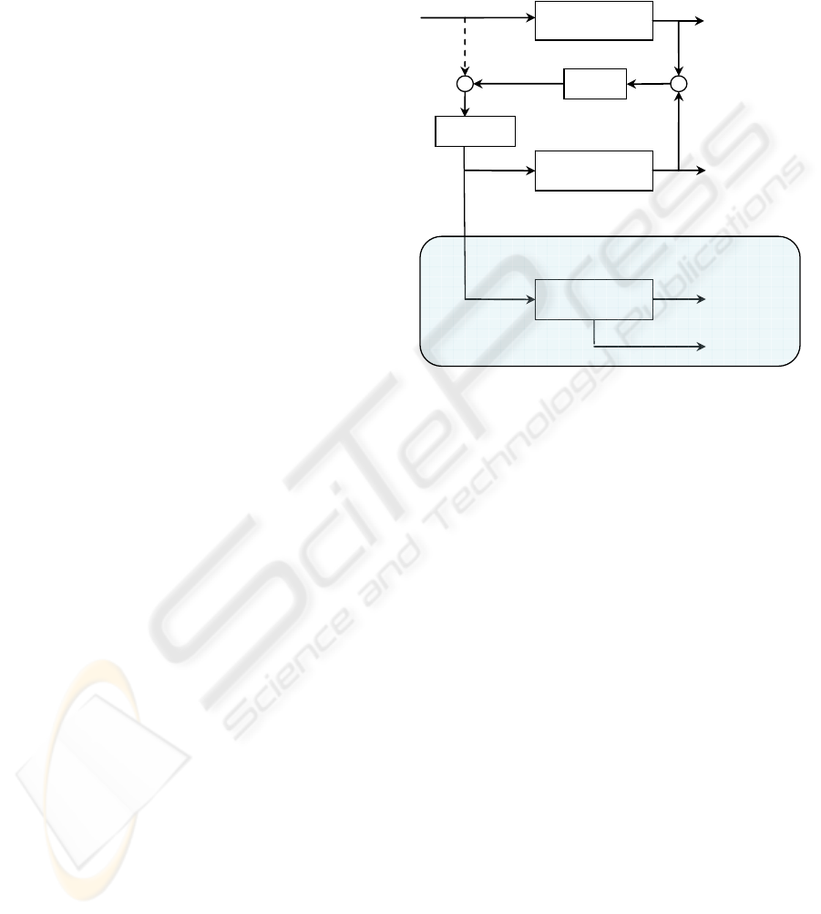
3.1 System Architecture
Figure 3 shows the basic architecture which we have
adopted. In this architecture, we implement as part
of the sensor module a slightly modified Luenberger
observer, with a quantizer included in the
compensation so that small corrections to the
modeled system are ignored, until the model error
reaches a level that requires correction. This
minimizes the data flow associated with the
correction to the modeled system.
G(z)
G
Est
(z)
L(z)
A
ctualSystem
ModeledSystem
ObserverCompensator
u(
k
)input y(
k
)
Plantoutput
x
O
(k)
Observedstate
y
O
(k)
Observeroutput
Quantizer
G
Est
(z)
ModeledSystem
y
O
(
k
)
Observeroutput
S
enso
r
DataAggregator/Web
S
erve
r
y
Err
(k)y
Comp
(k)
u
O
(k)
+
+
+
‐
Figure 3: Distributed Synchronised State Observer
Architecture.
An identical model of the system is then
incorporated into the data aggregator or Web server,
which then provides data to the Web client. Indeed it
may even be possible to incorporate the observer
directly into the Web client, thereby minimising
Web traffic and improving client interactivity.
The consequence of this is that the
communication that needs to occur from the sensor
nodes is reduced, thereby reduce resource usage. It
also has the potential to provide a more responsive
and accurate client side interaction (since the Web
client can use the model to support more rapid
interactions).
3.2 Design Modeling
The proposed architecture can be modeled as
follows. The standard form for the linear relation, at
time k, between the input vector u(k), system state
vector x(k) (which may not be directly measurable)
and the vector of observable outputs y(k) in a
discrete system is:
)()()(
)()()1(
kDukCxky
kBukAxkx
+=
+
=
+
(1)
WINSYS 2009 - International Conference on Wireless Information Networks and Systems
8

Where A, B, C and D are matrices that define the
model of the system dynamics, and are obtained
through conventional control system modelling
techniques.
Assuming that we are able to construct a
sufficiently accurate representation of this system,
then for a normal Luenberger observer we have:
)()()(
)()()1(
kDukCxky
kBukAxkx
OOO
OOO
+=
+
=+
(2)
where x
O
and y
O
are the estimates of the system state
and the system output, and u
O
is the input to the
observer. But:
(
)
()
()()
)()()(
)()(
)()()(
kykyLkuQ
kLykuQ
kykuQku
O
Err
CompO
−+=
+=
+=
(3)
Where Q is the quantization function and L is the
Luenberger compensator matrix. (Note that the
derivation of these is beyond the scope of this paper,
but is well covered in most control texts). Therefore,
merging equations (2) and (3) gives:
()
)()(
)()()1(
kykyQBL
kQBukAxkx
O
OO
−
+
+
=+
(4)
For the observer to provide an accurate
representation of the system state, we need the
observer state error to approach zero as
∞
→k
. i.e.:
()
()( )
()()
()
)(
)()()()(
)()()()(
)()(
)()()()(
)1()1()1(
)()()(
keQBLCA
kxkxQBLCkxkxA
kykyQBLkxkxA
kBukAx
kykyQBLkQBukAx
kxkxke
kxkxke
OO
OO
OO
O
O
−=
−−−=
−−−≈
−−
−++=
+−+=+
−=
(5)
The observer will therefore converge when the
eigenvalues of
QBLCA−
all have negative real
values.
However, in the case of typical environmental
monitoring, we will be sensing a system that we are
not controlling. We would therefore treat u(k) as a
disturbance input which we cannot directly monitor.
For example, if we are designing a Web interface to
a system that monitors temperatures throughout a
building, then someone opening a window may lead
to the entry of cold air, and hence temperature
fluctuations. Given that our only information is the
sensor data, we therefore can consider how rapidly
our observer can track these variations. In this case:
()
)()(
)()(
kykyQL
kQLyku
O
ErrO
−=
=
(6)
And therefore:
()
)()()()1( kykyQBLkAxkx
OOO
−+=+
(7)
And hence:
(
)
)()()1( kBukeQBLCAke −−≈+
(8)
The stability criteria remain the same, but we can
now determine the responsiveness of the system to
disturbance rejection, and hence the ability of the
observer to track variations.
Appropriate selection of the model parameters,
as well as the observer compensator and quantizer,
will therefore allow us to select the minimal data
stream rate between the sensor observer and the
Web client observer that achieves the desired
observer accuracy. Where applications require less
accuracy, we can tune the compensator and
quantizer to reduce the data rates.
3.3 Design Considerations
Given the baseline architecture, we can now move to
consideration of the issues this raises, and how it
relates to the design of Web-based monitoring. In
particular:
1. How accurately can we model the system being
monitored, and what are the consequences (in
resource utilization) of inaccuracies in the model.
2. What are consequences for sensor and client
synchronization of typical network impacts on
the data stream – i.e., network delays, packet
drops, etc.
3. What additional information needs to be passed
between the sensor observer and the Web client
observer in order to ensure that synchronization
is retained in the event of network delays, packet
drops and other forms of disturbances?
4. To what extent is it possible to implement a
typical state observer directly within a Web page,
so that it operates on the client-side, and hence
provides improved interactivity?
5. What additional processing burden does the
implementation of the observer place on both the
sensor module and the Web client, and how do
these additional resources compare to those
USING SYNCHRONIZED LIGHTWEIGHT STATE OBSERVERS TO MINIMISE WIRELESS SENSOR RESOURCE
UTILISATION
9
saved through possible reductions in the data
stream which must be communicated?
In the latter part of this paper we will focus on a
consideration of the last two of these questions – as
an initial demonstration of the potential resource
savings is a crucial first step in justifying the
approach. It is only worth deeper analysis of issues
such as model robustness and error correction if the
approach clearly shows merit in terms of reducing
resource utilization in Web-enabled sensors (or
conversely, enabling accuracy improvements for a
given resource usage level). Consideration of the
first three of these design considerations is ongoing
and will be reported in subsequent publications.
4 PERFORMANCE
EVALUATION
In order to evaluate the approach – and in particular
the potential ability to optimize the trade-off
between accuracy of the web-monitoring of
distributed sensor data and the resources required for
this monitoring, we have implemented (in
MATLAB) a simulation of a simple thermal system
and associated sensor configuration, as well as an
associated prototype of a Web interface that
incorporates a Web client-side state observer.
This initial implementation (which is much
simpler than that which would typically exist in a
real system – but nevertheless allows evaluation of
the approach) comprised a simulation of a simple
model of a two-room house, which had a specified
thermal resistance between the rooms and between
each room and the outside environment. Both rooms
also had substantial thermal capacitance. The system
state could therefore be modelled by the following
variables:
[]
T
E
kTkTkTkTkTkx )()()()()()(
2211
&&
=
(9)
Where
)(kT
E
is the external temperature,
)(
1
kT
and
)(
2
kT
are the temperatures in the two rooms,
and
)(
1
kT
&
and
)(
2
kT
&
are the corresponding rates of
temperature change. Only two system values are
actually measured directly by sensors – the external
temperature
)(kT
E
and the temperature in one of the
rooms
)(
2
kT
- so y(k) is given by:
[]
T
E
kTkTky )()()(
2
=
(10)
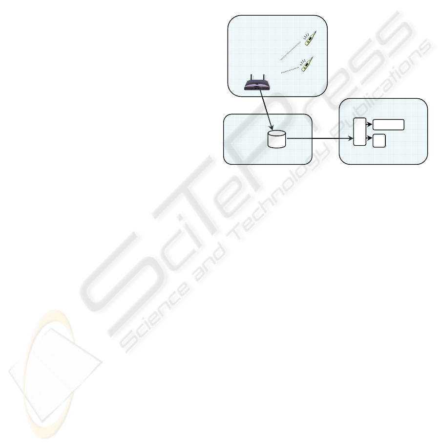
4.1 Implementation
The aim was to allow monitoring of these
temperatures within a Web browser. Figure 4 shows
the architecture for the simulation. In this
implementation we have constructed the client
observer using Javascript embedded within the Web
page. The system state output from the client
observer (i.e. estimates of the temperature values
and rates of temperature change) is used to support
rendering of, and interaction with, the sensor data.
WebBrowser
WebServer
S
imulatedSensorNetwor
k
Z
igbeeNetwork
Coordinator
Temperature
Sensors
Data
Repositor
y
A
JAX
Controller
Display
Observer
Model
Observer
Model
Figure 4: Example architecture for a typical Web client
state observer.
The Javascript also uses an AJAX-like approach
to query the Web server for any new quantized
observer compensator data which, when available, is
used as input to the Web client observer in order to
correct its modelled state. Whilst this example is
relatively simplistic, it does demonstrate the general
approach and allows evaluation of the performance.
4.2 Data Flow Improvements
The client-side implementation allows evaluation of
the improved interactivity that is enabled by
including the state observer directly within the web
pages (such as zooming into sensor trend data or
interpolating spatially between sensor values). The
more substantial benefits however are potentially
achieved through reduction in the sensor data rates.
In order to evaluate this, we analysed the outputs of
the simulated system under varying circumstances,
and in particular considered the data transmissions
associated with the quantized observer compensator
data that are required to correct both the sensor
observer and the client observer.
In our simulated system we introduced various
disturbances to the system (equivalent to sudden
temperature variations that were not predicted by the
WINSYS 2009 - International Conference on Wireless Information Networks and Systems
10

simple model used), and looked at the level of data
that was required to be transmitted by the sensor in
order to retain synchronization between the sensor
observer and the Web client observer. We also
considered the implications on these data flows of
inaccuracies in the observer model.
Figure 5 shows the Matlab model used for the
simulations to compare the system output and
observer transmission rates under conditions of a
disturbance to the system.
4.3 Resource Usage
We can see the implications of this reduction in data
flow by considering the implications in terms of the
average power usage in a typical sensor
configuration.
Table 1: Typical data rates associated with different
configurations of simulated temperature monitoring.
Configuration
Data
Rate
(transmit
s / day)
Baseline system with no observers
No sensor-side or client-side observer,
and system transmits raw sensor data
from both temperature sensors (rate=1
sample/sec)
86,400
System with implemented observers
No disturbances,
)(kT
E
stable, observer
is completely accurate (Note:
resynchronization transmissions occur
every 10 minutes)
144
(0.2%)
No disturbances,
)(kT
E
stable, observer
has minor inaccuracies that lead to drift
462
(0.5%)
No disturbances,
)(kT
E
stable, observer
has major inaccuracies that lead to drift
2,712
(3.1%)
External temperature
)(kT
E
sinusoidally
varying by 10 degC with 24 hour period,
observer has minor inaccuracies that lead
to drift
3,842
(4.4%)
Internal temperature
)(
2
kT
varying in a
square wave by 10 degC with a 2 minute
period
7,563
(8.8%)
In our scenario, the base sampling rate was 1
sample (from each sensor) per second. A typical
Zigbee-based single temperature sensor that
immediately transmitted each sensor value would
operate on the following 1 second cycle:
• Reading sensor + housekeeping: 10mA, 0.4
mSec
• Transmitting data: 40mA, 1 mSec
• Asleep: 0.001mA, remainder of time
Giving an average power usage of 0.045mA (or
approximately 92 days from a 100mAh battery).
The data rate required with the state observer
implemented depended upon a number of factors,
but a typical scenario would reduce the transmitted
data to an average of approximately one sample
every 15 seconds (though, as observed above, this
was highly dependant upon the volatility of the data
and the accuracy of the model). The additional
processing time to implement the observer in the
sensor module will depend substantially upon the
particular module used, though a quick prototype on
a Jennic JN5139 Zigbee module indicated that the
observer could be implemented in approximately
140 µSec per cycle. This gives:
• Reading sensor + housekeeping: 10mA, 0.54
mSec.
• Transmitting data: 40mA, 1 mSec (every 15
th
sample)
• Asleep: 0.001mA, remainder of time
This gives an average power usage of 0.009mA
(or approximately 460 days on a 100mAh battery) –
a very significant improvement.
In cases where the sensor data is very volatile,
and the observer is not able to track, and hence there
is absolutely no reduction in sensor data that is being
transmitted, the increased power usage due to the
inclusion of the observer minimal – a 3% increase
from 0.045mA to 0.046mA.
5 CONCLUSIONS
In this paper we have considered an architectural
model that includes into the client-side Web pages a
distributed state observer that is synchronized with
identical observers in real-time wireless sensors.
Whilst still preliminary, our initial results have
demonstrated that significant gains may be possible
in terms of minimizing resource utilization within
the sensors (by limiting the data that has been
wirelessly transmitted – potentially at significant
power cost) and potentially also improving the
interactivity of the client-side experience (though
this needs further consideration).
Further work on the development of this
approach will consider the extent to which we can
construct useful models of the dynamics of the
physical systems being monitored by the sensors,
and the implications of these models as the sensors
become more distributed.
USING SYNCHRONIZED LIGHTWEIGHT STATE OBSERVERS TO MINIMISE WIRELESS SENSOR RESOURCE
UTILISATION
11
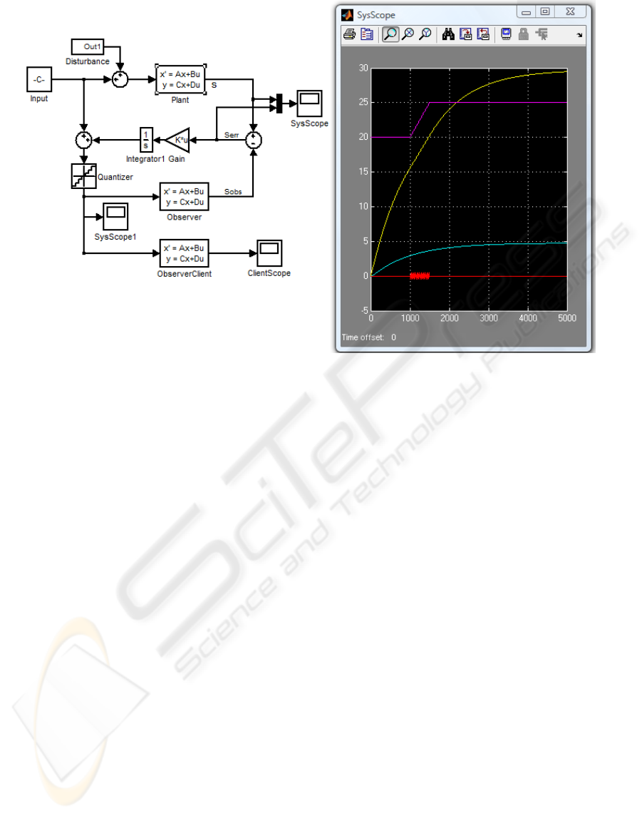
Figure 5: Example temperature tracking simulation and associated data rates.
Further work will also consider how reliably the
multiple observers can remain synchronized in the
presence of network delays, data loss, etc.
Finally, we are also constructing a more
substantial physical implementation of a sensor
network which can be used as a test bed
environment to validate our model simulations.
ACKNOWLEDGEMENTS
The authors wish to acknowledge the Centre for
Real-Time Information Networks (CRIN) at the
University of Technology, Sydney, in supporting
this research project.
REFERENCES
Costa, P., Picco, G. P., & Rossetto, S. (2005). Publish-
subscribe on sensor networks: a semi-probabilistic
approach.
Delin, K. A. (2002). The Sensor Web: A Macro-
Instrument for Coordinated Sensing. Sensors, 2(1),
270-285.
Ellis, G. (2002). Observers in Control Systems: A
Practical Guide: Academic Press.
Ganesan, D., Ratnasamy, S., Wang, H., & Estrin, D.
(2004). Coping with irregular spatio-temporal
sampling in sensor networks. SIGCOMM Comput.
Commun. Rev., 34(1), 125-130.
Gaynor, M., Moulton, S. L., & Welsh, M. (2004).
Integrating Wireless Sensor Networks with the Grid.
IEEE INTERNET COMPUTING, 32-39.
Huang, Y., & Garcia-Molina, H. (2004).
Publish/Subscribe in a Mobile Environment. Wireless
Networks, 10(6), 643-652.
Ishwar, P., Kumar, A., & Ramchandran, K. (2003).
Distributed Sampling for Dense Sensor Networks: A"
Bit-Conservation Principle".
Krishnamachari, B., Estrin, D., & Wicker, S. (2002).
Modelling Data-Centric Routing in Wireless Sensor
Networks.
Li, H., & Fang, J. (2007). Distributed Adaptive
Quantization and Estimation for Wireless Sensor
Networks. Signal Processing Letters, IEEE, 14(10),
669-672.
Polastre, J., Hill, J., & Culler, D. (2004). Versatile low
power media access for wireless sensor networks.
Paper presented at the 2nd international conference on
Embedded networked sensor systems.
The Zigbee Alliance. (2008). Retrieved 22-Oct, 2008,
from http://www.zigbee.org/en/index.asp.
WINSYS 2009 - International Conference on Wireless Information Networks and Systems
12
