
DIFFERENTIAL-DRIVE STEERING SYSTEM USING PLANETARY
GEARING FOR OMNIDIRECTIONAL MOBILE ROBOT
Hideo Kitagawa
Department of Electronic Control Engineering, Gifu National College of Technology
Kamimakuwa, Motosu, Gifu, Japan
Takashi Ohno, Yuki Ueno, Kazuhiko Terashima
Department of Production Systems Engineering, Toyohashi University of Technology
Hibarigaoka, Tempaku, Toyohashi, Japan
Keywords:
Mobile robots, Movement, Robot kinematics, Vehicles, Wheels, Ride comfort.
Abstract:
Holonomic omnidirectional mobile robot is useful with its high mobility in narrow or crowded area, and
omnidirectional robot equipped with normal tires is desired for difference excess, vibration suppression and
ride comfort. Caster-drive mechanism using normal tire has been developed to realize a holonomic omni-
diredctional robot, however, there remains some problems. This paper presents effective systems to control
the caster-drive wheels of omnidirectional mobile robot. Differential-Drive Steering System (DDSS) using
planetary gearing is proposed to improve the operation ratio of motors. DDSS generates driving and steering
torque effectively from two motors. Simulation results show the proposed system is effective for holonomic
omnidirectional mobile robots.
1 INTRODUCTION
An omnidirectional robot is highly maneuverable in
narrow or crowded area including residences, offices,
warehouses and hospitals. It can be applied to an
autonomous mobile robot in a factory, a wheelchair
and so on. Several kinds of omnidirectional mobile
robots and their applications have been developed by
(West, 1992), (Pin, 1994), (Damoto, 2002) and (Kita-
gawa, 2008). However, these robots realized their
omnidirectional motion by using special wheels such
as mechanum wheels, ball wheels, omni-disks and
omni-wheels.
To improve the ride comfort, vibration suppres-
sion, slippage reduction and ability of difference ex-
cess, omnidirectional robots equipped with normal
tires have been strongly required. (Arai, 1981) pro-
posed an omnidirectional vehicle equipped with nor-
mal tires. However, it was a non-holonomic vehicle
which has to adjust the direction of wheels before
changing the moving direction of vehicle.
Holonomic omnidirectional vehicles, which can
move in any direction without changing the direc-
tion of tires beforehand, equipped with normal tires
include dual-wheel type by (Wada, 2000) and caster-
drive(active-caster) type by (Wada, 1996).
The dual-wheel type has problems as follows.
Number of wheels is limited to two, and it is impos-
sible to get high friction or to adapt a rough terrain
by synchronous drive of many wheels. Moreover, a
passive wheel is needed to stabilize the posture of ve-
hicle.
The caster-drive wheel has offset between the
steering axis and the center of wheel. The wheel
can move in any direction by controlling the steer-
ing axis and the driving wheel independently by using
two motors. A holonomic omnidirectional motion of
a robot can be realized by using two or more caster-
drive wheels.
However, the caster-drive wheel has a problem as
follows. When the vehicle is in steady motion includ-
ing straight motion and rotation with constant curva-
ture, only the driving motor works and the steering
motor becomes idle. When the vehicle changes its
moving direction, high load is applied to the steering
motor. Therefore, high power is required both for the
driving and steering motor. It causes increase of mass.
The aim of our research is to develop a holonomic
omnidirectional mobile robot with caster-drive wheel
minimizing the motor power by using the interference
of output of two motors. New gearing mechanism is
proposed to realize the interference.
171
Kitagawa H., Ohno T., Ueno Y. and Terashima K. (2009).
DIFFERENTIAL-DRIVE STEERING SYSTEM USING PLANETARY GEARING FOR OMNIDIRECTIONAL MOBILE ROBOT.
In Proceedings of the 6th Inter national Conference on Informatics in Control, Automation and Robotics - Robotics and Automation, pages 171-176
DOI: 10.5220/0002191101710176
Copyright
c
SciTePress
Steering axis
r
s
w
O
X
Y
Y
w
X
w
s
O
w
(x
w
,y
w
)
s
Contact point
θ
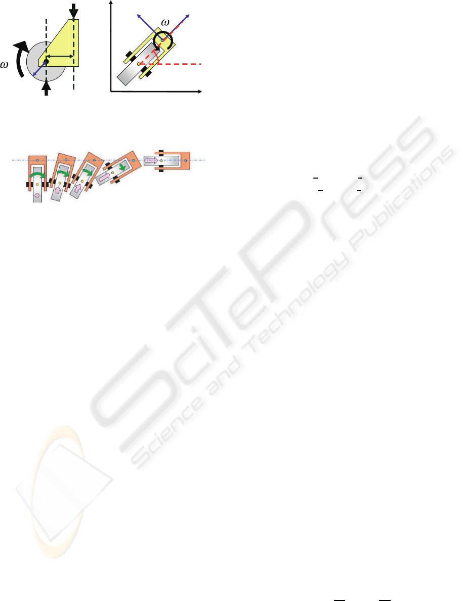
Figure 1: Caster-drive wheel.
Figure 2: Lateral motion to right.
2 PRINCIPLE
2.1 Omnidirectional Motion using
Caster-Drive Wheel
The principle of holonomic omnidirectional motion
using caster-drive wheels is described in this section.
Figure 1 shows the caster-drive wheel. The position
and orientation of wheel can be represented by the po-
sition O
w
(x
w
,y
w
) of steering axis and the orientation
θ
s
from the contact point between the wheel and the
ground to the steering axis with reference to the fixed
frame O− XY.
By rotating the driving wheel with the angular ve-
locity ω
w
, velocity ˙x
w
= rω
w
generates in the direc-
tion of X
w
axis. Here, r is the radius of driving wheel.
By rotating the steering axis with the angular velocity
ω
s
, velocity ˙y
w
= −sω
s
would generate at the cen-
ter of wheel in the direction of Y
w
axis. Here, s is
the offset between the steering axis and the center of
driving wheel in the direction of X
w
. However, react-
ing velocity ˙y
w
= sω
s
generates at the steering axis in
the direction of Y
w
axis, because the position of the
driving wheel is fixed by the friction with the ground.
Therefore, the velocity (˙x
w
, ˙y
w
) of caster-drive wheel
can be controlled by changing ω
w
and ω
s
.
Figure 2 shows an example of motion. The initial
orientation θ
s
of the wheel is set to be θ
s
= π/2 in
the frame O − XY. The motion as shown in Fig. 2
can be given by changing ω
w
and ω
s
appropriately.
Even though the rotating wheel itself can not generate
lateral motion to the right, the lateral motion of the
robot, which is fixed to the steering axis, is realized.
Each wheel does not have to control the orienta-
tion of the robot by itself.
The direct kinematic equation is denoted by the
state vector x
w
= [x
w
,y
w
]
T
and the input vector u
w
=
[ω
w
,ω
s
]
T
as
˙x
w
= B
w
u
w
, (1)
where
B
w
=
rcosθ
s
−ssinθ
s
rsinθ
s
scosθ
s
. (2)
The inverse kinamatic equation becomes
u
w
= B
−1
w
˙x
w
, (3)
where
B
−1
w
=
1
r
cosθ
s
1
r
sinθ
s
−
1
s
sinθ
s
1
s
cosθ
s
. (4)
Holonomic omnidirectional motion (˙x, ˙y,
˙
θ) of a
mobile robot can be achieved by using two caster-
drive wheels or more. Furthermore, synchronous
drive with arbitrary number of wheels and rotation
mechanism yields three dimensional holonomic om-
nidirectional motion by three motors.
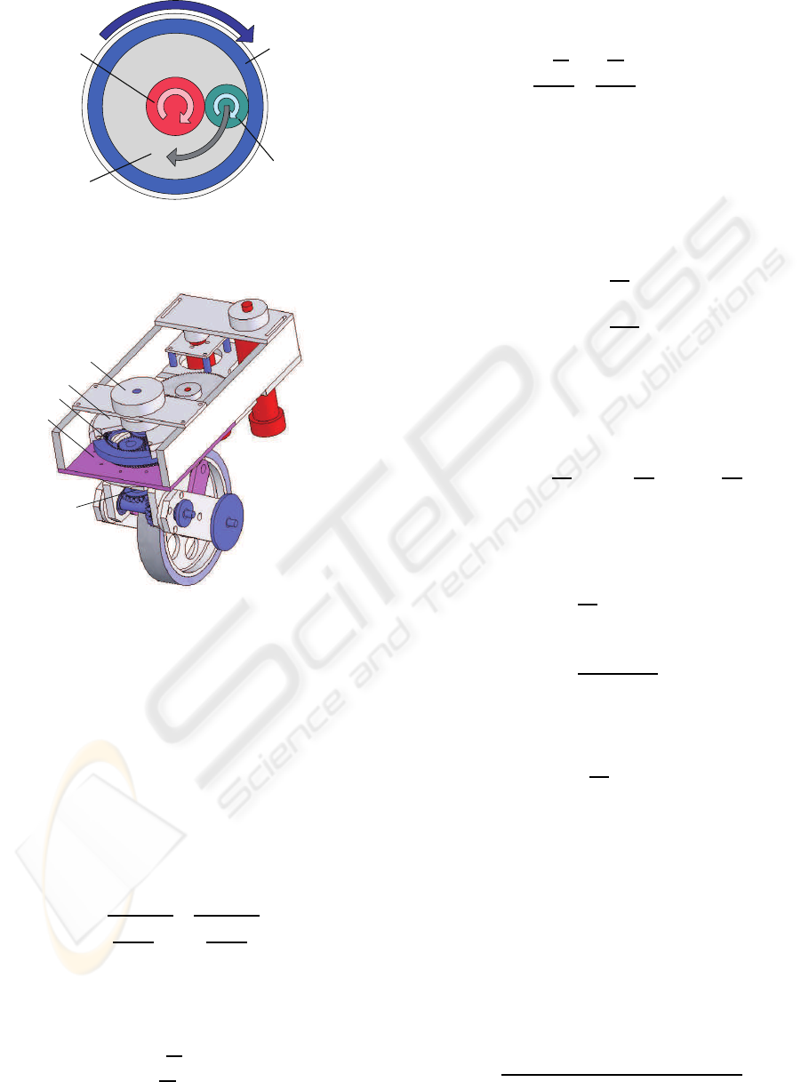
2.2 Differential-Drive Steering System
(DDSS)
In this section, we develop a useful method for con-
structing a caster-drivewheel using Differential-Drive
Steering System (DDSS). The DDSS outputs driv-
ing and steering velocities from two motors using
differential-drive gearing.
Figure 3 shows the principle of the DDSS. Just
like a usual planetary gearing, it is composed of sun
gear(A), outer ring gear(B), planet gear(C) and planet
carrier(D). The planet carrier(D) holds the planet
gear(C) and rotates relative to the sun gear(A) and the
outer ring gear(B). However, unlike usual planetary
gearing, the DDSS is 2-input 2-output system with-
out fixing any component. A and B are independently
driven by two motors. C and D provide output torque.
Figure 4 shows the mechanism of the DDSS. D,
which is fixed to the chassis(E), provides the steering
torque, and C, which leads to the driving wheel via
the bevel gear, provides the driving torque.
Let ω
A
, ω
B
, ω
C
and ω
D
be the angular velocity of
A, B, C and D in Fig. 3, and Z
A
, Z
B
and Z
C
be the
number of teeth of A, B and C, respectively.
When ω
D
= 0, the steering angular velocity ω
s
be-
comes zero, and we obtain
ω
A
= −
Z
B
Z
A
ω
B
= −
Z
C
Z
A
ω
C
, (5)
ω
D
= 0. (6)
ICINCO 2009 - 6th International Conference on Informatics in Control, Automation and Robotics
172
ω
B
A
B
C
D
ω
D
ω
A
ω
C
Figure 3: Principle of Differential-Drive Steering System
(DDSS).
A
B
C
D
E
Figure 4: Mechanism of DDSS.
When ω
C
− ω
D
= 0, the driving angular velocity
ω
w
becomes zero because C does not rotate between
A and B, and we obtain
ω
A
= ω
B
= ω
C
= ω
D
. (7)
The direct kinematic equation, which derives driv-
ing and steering output u
w
= [ω
w
,ω
s
]
T
from motor in-
put u
P
= [ω
A
,ω
B
]
T
, can be described as
u
w
=
ω
C
− ω
D
ω
D
= B
P
u
P
, (8)
where
B
P
=
"
−
Z
A
Z
B
Z
C
(Z
A
+Z
B
)
Z
A
Z
B
Z
C
(Z
A
+Z
B
)
Z
A
Z
A
+Z
B
Z
B
Z
A
+Z
B
#
. (9)
The inverse kinematic equation becomes
u
P
= B
−1
P
u
w
, (10)
where
B
−1
P
=
"
−
Z
C
Z
A
1
Z
C
Z
B
1
#
. (11)
Next, we derive the motor power ratio of the
DDSS. Joint torques T
A
, T
B
, T
C
and T
D
of A, B, C
and D, respectively, are given by
T
C
T
D
=
"
−
Z
C
Z
A
Z
C
Z
B
Z
A
+Z
C
Z
A
Z
A
+Z
C
Z
B
#
T
A
T
B
, (12)
where positive direction of each torque is same as that
of angular velocity in Fig. 3.
For an omnidirectional mobile robot with the
DDSS, steady motion including straight motion and
rotation with constant curvature is achieved by ω
s
(=
ω
D
) = 0. When ω
s
= 0 (T
D
= 0), the joint torques are
given from (12) by
T
A
= −
Z
A
Z
B
T
B
, (13)
T
C
= −
2Z
C
Z
A
T
A
, (14)
T
D
= 0. (15)
The power ratio of two motors is given from (5) and
(13) by
P
A
: P
B
= T
A
ω
A
: T
B
ω
B
=
−
Z
A
Z
B
T
B
−
Z
C
Z
A
ω
C
: T
B
Z
C
Z
B
ω
C
= 1 : 1 (16)
On the other hand, when ω
w
= 0 (T
C
= 0), the joint
torques are given from (12) by
T
A
=
Z
A
Z
B
T
B
, (17)
T
C
= 0, (18)
T
D
=
2(Z
A
+ Z
C
)
Z
A
T
A
. (19)
The power ratio is given from (7) and (17) by
P
A
: P
B
= T
A
ω
A
: T
B
ω
B
=
Z
A
Z
B
T
B
ω
B
: T
B
ω
B
= Z
A
: Z
B
. (20)
Letting the diameter of sun gear and planet gear be
the same in Fig. 1 yields
P
A
: P
B
= 1 : 3. (21)
2.3 Operation Ratio of Motors
In this section, we discuss the operation ratio of mo-
tors by comparing the DDSS to a conventional caster-
drive wheel. We define the operation ratio δ of motors
as
δ =
(Sum of motor power in motion)
(Sum of rated power of motors)
. (22)
DIFFERENTIAL-DRIVE STEERING SYSTEM USING PLANETARY GEARING FOR OMNIDIRECTIONAL
MOBILE ROBOT
173
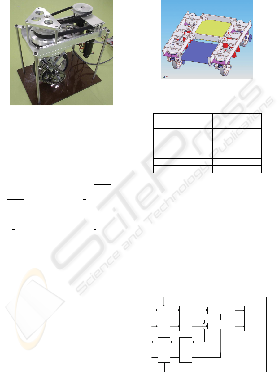
Figure 5: Prototype DDSS.
The ratio (P
A0
: P
B0
) of rated power of two motors
used in the DDSS is set to be 1:1. The ratio of rated
power used in conventional method is also set to be
1:1 as denoted in (Wada, 1996).
We calculate the operation ratio δ in case of driv-
ing motion (T
D
= 0). Let P be the sum of motor
output power needed to achieve the motion. The re-
sult of the conventional method is δ =
P
P
A0
+P
B0
= 0.5
from P
A0
= P
B0
= P. The result of the DDSS is
δ =
P
P
A0
+P
B0
= 1 from P
A0
= P
B0
=
P
2
.
Next, we calculate δ in case of steering motion
(T
C
= 0). The result of conventional method is P
A0
=
P
B0
= P and δ = 0.5. The result of the DDSS is P
A0
=
P
B0
=
3
4
P and δ = 0.67, because P
B0
=
3
4
P from (21).
The output power of motors can be decreased by
using the DDSS as a caster-drive wheel because of its
high operation ratio of motors. It means that the size
of robot become smaller by using the DDSS.
3 CONSTRUCTION OF
OMNIDIRECTIONAL MOBILE
ROBOT
We constructed a prototype model of the DDSS to
check the availability of proposed mechanism as
shown in Fig. 5. Torques of two motors are trans-
mitted to the sun gear(A) and the outer ring gear(B)
by the timing belts, and driving and steering torques
are generated. Effectiveness of the proposed DDSS
was confirmed by this apparatus.
Figure 6 and Table 1 show picture and specifi-
cation of an omnidirectional mobile robot with four
DDSS wheels, respectively. The proposed omnidi-
rectional robot has capability of climbing slope of 10
Figure 6: Omnidirectional Mobile Robot.
Table 1: Specification of Omnidirectional Mobile Robot.
Size (D × W) 600 × 600 [mm]
Weight 70 [kg]
Motor power 150 [W] × 8
Max. velocity 6 [km/h]
Max. acceleration 0.5 [m/s
2
]
Max. slope angle 10 [deg]
Max. step difference 60 [mm]
Max. loading weight 100 [kg]
[deg], accelerating 0.5 [m/s
2
] and exceeding differ-
ence of 60 [mm] with carrying load of 100 [kg].
4 SIMULATION
4.1 Simulation Method
To show the performance of the DDSS, simulations
are conducted. The simulation model is constructed
by SolidWorks and DADS. The radius r of the wheel
and the offset s shown in Fig. 1 were given as r = 80
[mm] and s = 50 [mm], respectively.
sr
ω
rM 1
ω
B
P
-1
B
W
-1
Unit
model
r
x
r
y
B
P
B
W
x
y
wr
ω
rM 2
ω
T
G1
T
G2
θ
w
ω
s
ω
Motor model 1
Motor model 2
1M
ω
2M
ω
s
.
.
.
.
Figure 7: Control system of DDSS.
ICINCO 2009 - 6th International Conference on Informatics in Control, Automation and Robotics
174
0 2 4 6 8 10
Vx[m/s]
time[s]
y positon[m]
time[s]
x positon[m]
y positon[m]
x positon[m]
time[s]
time[s]
Vy[m/s]
time[s]
ωMs[rad/s]
time[s]
ωs[rad/s]
time[s]
ωw[rad/s]
time[s]
ωMr[rad/s]
-1
0
1
2
0 2 4 6 8 10
-0.2
0
0.2
0 2 4 6 8 10
-500
0
500
1000
0 2 4 6 8 10
-1000
-500
0
500
1000
0 2 4 6 8 10
-20
0
20
0 2 4 6 8 10
0
5
10
0 2 4 6 8 10
0
5
10
0 2 4 6 8 10
-0.1
-0.05
0
0.05
-0.06 -0.04 -0.02 0
-2
0
2
4
6
8
10
Reference
Simulation
0.02
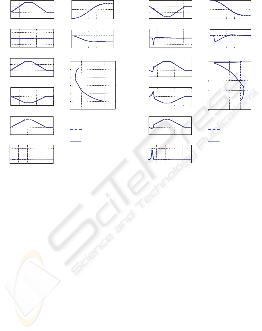
Figure 8: Simulation results (Vx = 6 km/h, Vy = 0 km/h).
Figure 7 shows the control system of a wheel used
in this simulation. The reference angular velocities
ω
M1r
and ω
M2r
are given by (3) and (10). The velocity
(˙x, ˙y) of the DDSS is given from the angular velocities
ω
M1
and ω
M2
and the steering angle θ
s
.
Four translational motions toward +X, –X, +Y and
–Y direction with maximum velocity of 6 [km/h] (=
1.67 [m/s]) and maximum acceleration of 0.5 [m/s
2
]
were examined. The initial value of θ
s
was set to be
zero in any case.
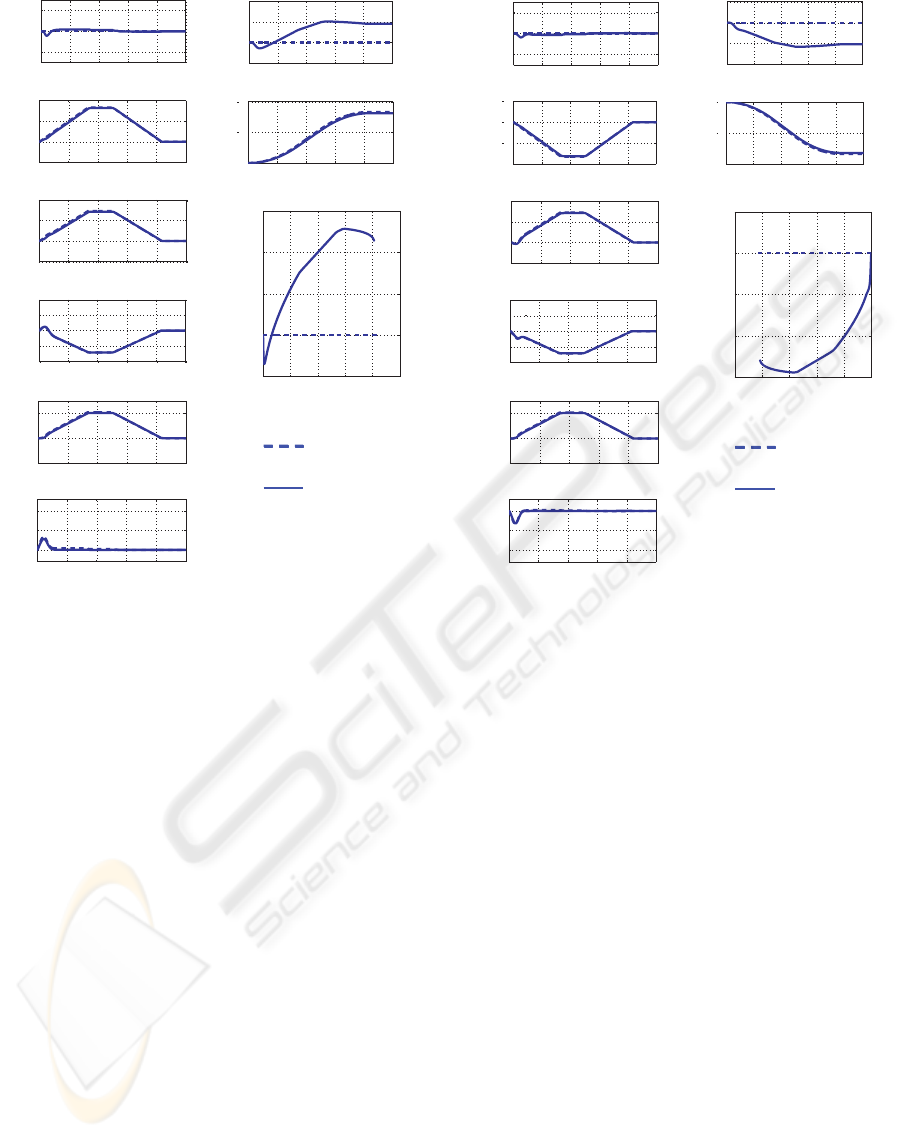
4.2 Simulation Results and Discussion
Figures 8 through 11 show the simulation results of
motions toward +X, –X, +Y and –Y direction, respec-
tively, from the initial state θ
s
= 0. Here, V
x
, V
y
, ω
Ms
,
ω
Mr
, ω
w
and ω
s
indicate the velocity in X-direction,
the velocity in Y-direction, the angular velocity of sun
gear motor, the angular velocity of outer ring gear mo-
tor, the angular velocity of wheel and the angular ve-
locity of steering axis, respectively.
As seen from these graphs, error from the refer-
ence trajectory is within 6 [cm] in any case. We can
also see the feature of caster-drive wheel. In Fig. 9,
the angular velocity ω
s
of steering axis becomes large
0 2 4 6 8 10
-2
-1
0
1
time[s]
Vx[m/s]
0 2 4 6 8 10
-0.1
-0.05
0
0.05
time[s]
y positon[m]
0 2 4 6 8 10
-10
-5
0
time[s]
x positon[m]
-0.06 -0.04 -0.02 0 0.02
-10
-8
-6
-4
-2
0
y positon[m]
x positon[m]
0 2 4 6 8 10
-0.2
0
0.2
time[s]
Vy[m/s]
0 2 4 6 8 10
-500
0
500
1000
time[s]
ωMs[rad/s]
0 2 4 6 8 10
0
5
10
time[s]
ωs[rad/s]
0 2 4 6 8 10
-20
0
20
time[s]
ωw[rad/s]
0 2 4 6 8 10
-1000
0
1000
time[s]
ωMr[rad/s]
-500
500
Reference
Simulation
Figure 9: Simulation results (Vx = – 6 km/h,Vy = 0 km/h).
in the beginning of motion because the moving direc-
tion is opposite to the initial direction θ
s
= 0.
5 CONCLUSIONS
We proposed Differential-Drive Steering System
(DDSS) for caster-drive wheel of holonomic omnidi-
rectional mobile robot. The DDSS can provide high
operation ratio of motors rather than conventional
caster-drive wheel. Numerical analysis, examination
by prototype model and simulation results showed ef-
fectiveness of the DDSS.
Future works include
• construction of an omnidirectional mobile robot
and experiments,
• posture control on rough terrain,
• application to an omnidirectional wheelchair.
ACKNOWLEDGMENTS
This work was supported by Scientific Grant-in-Aid
(No.19560271) and G-COE (Global Center of Excel-
DIFFERENTIAL-DRIVE STEERING SYSTEM USING PLANETARY GEARING FOR OMNIDIRECTIONAL
MOBILE ROBOT
175
10
Vx[m/s]
time[s]
y positon[m]
time[s]
x positon[m]
y positon[m]
x positon[m]
time[s]
time[s]
Vy[m/s]
time[s]
ωMs[rad/s]
time[s]
ωs[rad/s]
time[s]
ωw[rad/s]
time[s]
ωMr[rad/s]
0 2 4 6 8 10
-500
0
500
1000
0 2 4 6 8 10
-1000
-500
0
500
1000
0 2 4 6 8 10
-20
0
20
0 2 4 6 8 10
0
5
10
0 2 4 6 8 10
-1
0
1
2
0 2 4 6 8 10
-0.05
0
0.05
0.1
0 2 4 6 8 10
-0.02
0
0.02
0.04
0.06
0 2 4 6 8
-0.2
0
0.2
0 2 4 6 8 10
0
5
10
Reference
Simulation
Figure 10: Simulation results (Vx = 0 km/h, Vy = 6 km/h).
lence) Program “Frontier of Intelligent Human Sens-
ing” by the Japanese Ministry of Education, Culture,
Sports, Science and Technology.
REFERENCES
Arai, T., Nakano, E., Hashino, H., and Yamaba, K., 1981.
The Control and Application of “Omni-Directional
Vehicle (ODV)”. Proc. 8th IFAC World Congress,
1855–1860.
Damoto, R and Hirose, S., 2002. Development of Holo-
nomic Omnidirectinal Vehicle “Vuton-II” with Omni-
Discs. Journal of Robotics and Mechatronics, Vol.14,
No.2, 186–192.
Kitagawa, H., Miyoshi, T., and Terashima, K., 2008. Skill-
Assist Control of Omnidirectional Wheelchair Using
Human-Friendly Interface. Proc. IEEE Int. Conf. on
Robotics and Biomimetics, TuPA7.13.
Pin, F. G. and Killough, S. M., 1994. A new family of omni-
directional and holonomic wheeled platforms for mo-
bile robots. IEEE Trans. on Robotics and Automation,
vol.10, 480–489.
Wada, M. and Mori, S., 1996. Holonomic and omnidirec-
tional vehicle with conventional tires. Proc. IEEE Int.
Conf. on Robotics and Automation, 3671–3676.
Vx[m/s]
time[s]
y positon[m]
time[s]
x positon[m]
y positon[m]
x positon[m]
time[s]
time[s]
Vy[m/s]
time[s]
ωMs[rad/s]
time[s]
ωs[rad/s]
time[s]
ωw[rad/s]
time[s]
ωMr[rad/s]
-10 -8 -6 -4 -2 0
-0.06
-0.04
-0.02
0
0.02
0 2 4 6 8 10
-0.2
0
0.2
0 2 4 6 8 10
-2
-1
0
1
0 2 4 6 8 10
-0.1
-0.05
0
0.05
0 2 4 6 8 10
-10
-5
0
0 2 4 6 8 10
-1000
-500
0
500
1000
0 2 4 6 8 10
-500
0
500
1000
0 2 4 6 8 10
-10
-5
0
0 2 4 6 8 10
-20
0
20
Reference
Simulation
Figure 11: Simulation results (Vx = 0 km/h, Vy = – 6 km/h).
Wada, M., Takagi, A., and Mori, S., 2000. A Mobile
Platform with a Dual-wheel Caster-drive Mechanism
for Holonomic and Omnidirectional Mobile Robots.
Journal of Robotics Society of Japan, Vol.18, No.8,
1166–1172.
West, M. and Asada, H., 1992. Design of a holonomic
omnidirectional vehicle. Proc. IEEE Int. Conf. on
Robotics and Automation, 97–103.
ICINCO 2009 - 6th International Conference on Informatics in Control, Automation and Robotics
176
