
Use Case Maps as an Aid in the Construction
of a Formal Specification
Cyrille Dongmo and John A. van der Poll
School of Computing, University of South Africa, South Africa
Abstract. A Use Case Map (UCM) is a scenario-based visual notation
facilitating the requirements definition of complex systems. A UCM may be
generated either from a set of informal requirements, or from use cases
normally expressed in natural language. Natural languages are, however,
inherently ambiguous and as a semi-formal notation, UCMs have the potential
to bring more clarity into the functional description of a system. It may
furthermore eliminate possible errors in the user requirements. The semi-formal
notation of UCMs aims to show how things work generally, but is not suitable
to reason formally about system behaviour. It is plausible, therefore, that the use
of UCMs as an intermediate step may facilitate the construction of a formal
specification. To this end this paper proposes a mechanism whereby a UCM
may be translated into Object-Z.
1 Introduction
Use Case Maps (UCMs) gained popularity due to their applicability and adaptability
to various purposes [1-6]. In general a UCM is used for enhancing the understanding
and architecting of the behaviour of large, complex, and self-modifying systems [7].
A UCM facilitates the capturing of service functionality during the requirements
elicitation phase, during which requirements tend to be vague and often contradictory.
UCMs offer a comprehensible, by humans, representation of system scenarios and the
interactions among these that may be superimposed on the structure of components.
They combine in a single view the behavioural and architectural structure of a system.
UCMs also have the potential to serve as input to other specification and design
languages, given a suitable transformation or adaptation process is defined [8, 9].
Although formal methods may be used during most stages of the software
development process [12], the lack of a precise technique in Z to set up the
boundaries of a system during the early stages of development (e.g. capturing non-
functional requirements) makes it hard to grasp a system from scratch. The power of
Z (Object-Z) resides in its ability to enable a system specifier to think deeply about
the details of a system using the Established Strategy [10, 11] and not so much about
the higher-level architecture of the system. Despite the advantages of the use of
formal methods in producing quality software [13], they are mostly still not embraced
by industry. The reasons for this state of affairs may be varied, but in this work we
argue that one of the reasons is the lack of a step-by-step formal methodology capable
of embracing architectural and system boundaries. Therefore, we believe that a
Dongmo C. and van der Poll J. (2009).
Use Case Maps as an Aid in the Construction of a Formal Specification.
In Proceedings of the 7th International Workshop on Modelling, Simulation, Verification and Validation of Enterprise Information Systems, pages 3-12
DOI: 10.5220/0002195800030012
Copyright
c
SciTePress
framework to transform a UCM into Z/Object-Z would facilitate the construction of a
formal specification. A correct Z specification could be used in a reverse-engineering
approach to in turn enhance the original UCM. A more correct UCM may be vital,
since system designers may prefer to develop a system from a set of UCMs instead of
a formal description. In this sense the formal specification is often referred to as a
throwaway specification.
In section 2, we briefly review and illustrate some aspects of the UCM notation.
Section 3 presents an overview of Z and Object-Z. In section 4, we propose a
transformation process. Thereafter, in Section 5 we apply the process to a small case
study followed by the conclusions and further work in Section 6.
2 Overview of UCMs
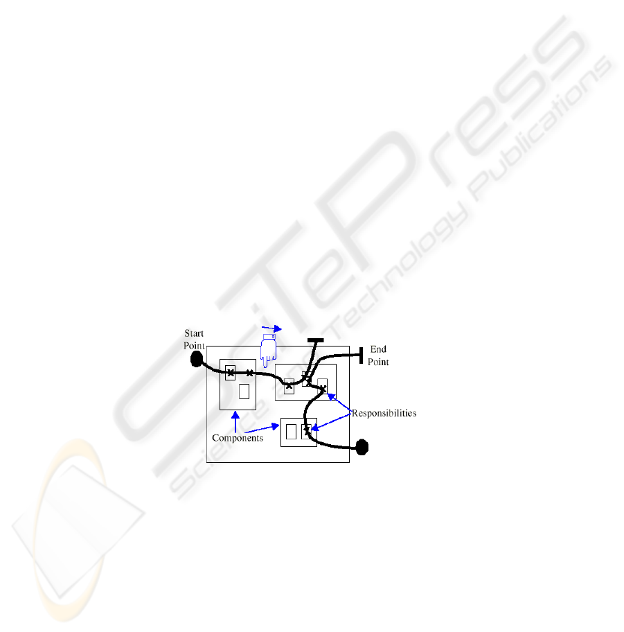
UCMs, originally developed by Buhr and Casselman [1, 2] embody a semi-formal
(graphical elements and prose descriptions) notation showing related and interacting
use cases in a map-like diagram (see Fig. 1). The progression of scenarios along use
cases is captured by paths shown as wiggle lines. UCM models describe service
functionalities with causal relationships between responsibilities, superimposed on
organisational structures of abstract components [1, 2]. A responsibility represents
generic processing, e.g. an operation, a task, an action, a function and so forth. The
strength of a UCM is in utilising a simple graphical notation to describe complex
systems.
A Start point is indicated by a black dot and is defined by a set of possible
triggering events and optionally a precondition. The execution of a path begins when
some triggering events occur and the precondition enabled.
A Responsibility is some generic processing as discussed above.
Fig. 1. A Use Case Map – Buhr [1].
A Path segment is a continuous line that chains path elements (see below) in an
ordered sequence. A hand and an arrow indicate the direction of the progression of a
scenario.
An End point is indicated by a vertical bar and is defined by a set of resulting
events and an optional postcondition that terminate the execution of a path.
Some other path elements are waiting places and stubs. A stub provides for path
abstraction and represents a place where a sub-map, called a plug-in, is needed but
whose details are presented elsewhere. When only one plug-in is needed, a static stub
4
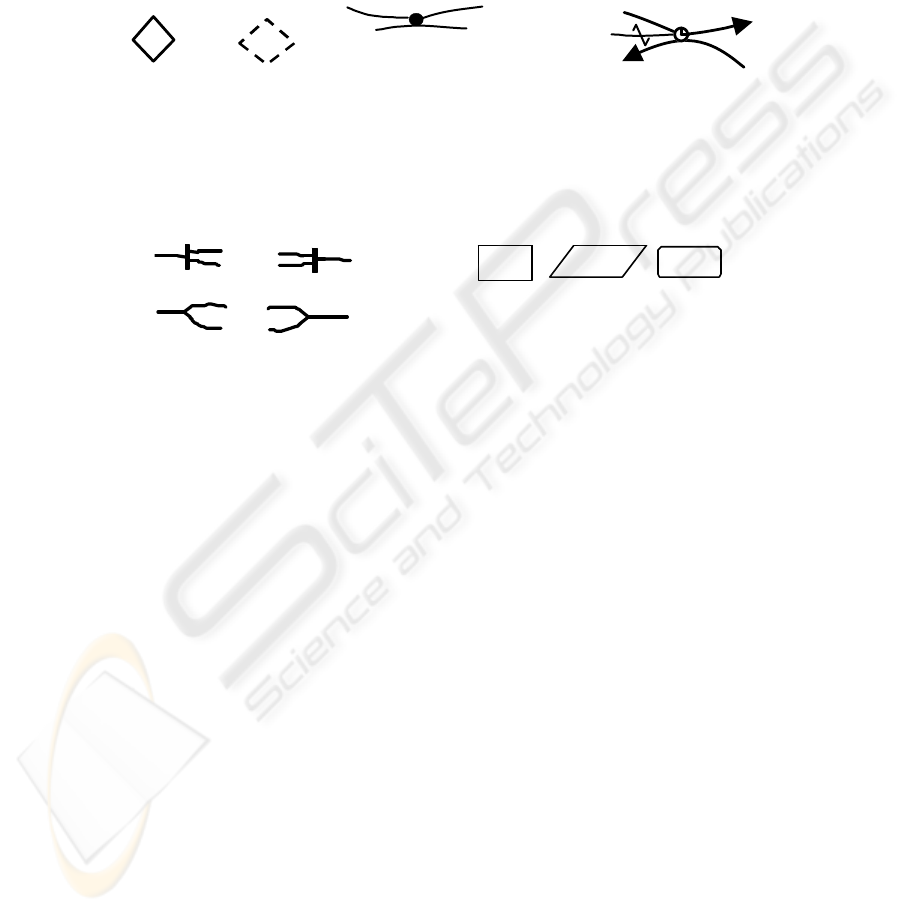
is used. Otherwise, a dynamic stub is used and a selection policy is used to select only
one plug-in at runtime [1]. A waiting place along a path segment indicates that the
execution is interrupted, waiting for a predefined unblocking event to occur. The path
in execution is called the main path and the one through which the triggering event
occurs is the triggering path. A timer is a special case of a waiting place where the
waiting time is predefined and a timeout path is used to initiate some action in case
timeout occurs before the triggering event. These concepts are depicted in Fig. 2.
Triggering path
Main
path
Main path
Clearing path
Timeout path
Waiting places
Timer
Static stub
D
y
namic stub
Fig. 2. UCM path elements – Buhr [1].
A UCM path is the execution route of one or more scenarios and may be composed of
a number of path segments interconnected by means of path connectors (see Fig. 3) to
achieve path coupling and express interactions between scenarios.
And
-
Fork And
-
j
oin
O
r-Fork
Or
-
Joi
n
Fig. 3. Path connectors.
Team Process
Objec
t
Fig. 4. UCM components.
An And-fork splits a path segment into 2 or more parallel paths. An And-join
merges 2 or more parallel paths into a single path. An Or-fork splits a single path into
2 or more alternative paths and an Or-join merges 2 or more alternative paths into a
single one. A UCM may be superimposed on a structure of abstract components that
describe software entities, for example objects, databases, processes, servers, etc. and
non-software entities like hardware, actors, etc. [1]. Each component performs
responsibilities bound to it. The following components, amongst others, are available:
A Team component is a generic component allowed to contain any other
component type including other teams.
A process is an autonomous, active component that may operate concurrently
with other processes. An object is a passive component that supports data or
procedural abstraction through an interface. Objects perform their own
responsibilities but do not have ultimate control on when they are activated. Further
and comprehensive overviews of the UCM notation appear in [1-3, 7].
3 Overview of Z and Object-Z
Z is a formal specification language based on first order logic and a strongly-typed
fragment of Zermelo-Fraenkel (ZF) set theory [13, 14]. The main construct in Z is the
5

schema (see Fig. 5). A state schema describes the static behaviour of a system while
operation schemas describe dynamic aspects of the system.
Declaration-part
Predicate-part
SchemaName
Fig. 5. Generic format of a Z schema.
Visibility list
Inherited classes
Type definitions
Constant definitions
State schema
Initial state schema
Operation schemas
History invariant
[ClassName
[generic parameters
]
Fig. 6. Generic form of a Class schema.
SchemaName represents the name of the schema. The declaration part includes
a list of typed variables, called components. Composed types are normally defined
from a list of Basic types identified during the construction of a specification.
The predicate part defines constraints or relationships between the components in
the declaration part, e.g. the state invariant.
Object-Z is an object-oriented extension of Z that uses class schemas (see Fig. 6)
to encapsulate Z schemas, and introduce the notion of system structure to standard Z.
Object-Z is discussed in detail in [15-17].
The visibility list restricts access to the attributes and operations of the class. A
class may inherit from other classes. Type and constant definitions are similar to
those of Z. A class schema includes only one state schema. The components of the
state schema are initialised to some realisable values. Operation schemas are similar
to those of Z. The history invariant constraints the order of the operations. An
example is given in Section 5.4.
4 Framework for Transforming a UCM into Object-Z
Although UCM as a semi-formal notation may share with natural languages some
limitations such as allowing ambiguous requirements, non-detection of errors, etc., it
has the advantage of encapsulating different types of information in a single view.
Thus, a drawback of a transformation process would be the loss of information (e.g.
when a UCM is transformed into a Message Sequence Chart, some information on the
scenario interactions is lost [18]).
We propose to use Z as an intermediate transformation step. This way we can
exploit the rigour of Z to allow for clear and precise definitions of static and dynamic
behaviour of systems, extracted from an input UCM. At the same time we use meta-
classes to extract necessary architectural information.
Thereafter we combine the Z schemas with the meta-classes to form the Object-Z
schemas. The architecture of this mechanism is presented in Fig. 7.
6

UCM
Z schemas
Meta-
cl as ses
Class
schemas
Step 1
Intermediate
models
Step 2
Fig. 7. Basic transformation strategy.
4.1 Relationships between UCM and Z/ Object-Z
To evaluate the feasibility of the above mechanism, we need to analyse the
relationships between the UCM and Z / Object-Z notations:
• Both notations are specification techniques that focus on systems functionalities at
the requirement level, but, can also be used during later stages of the software
development process.
• Their documentations include, for clarification purposes, natural language prose
aimed at explaining possible intricacies of UCMs and schemas.
• UCMs target the static, dynamic and architectural aspects of a system while Z
focuses on the static and dynamic aspects only. However, the architectural
component of UCMs can be compensated with the class structures of Object-Z.
• Users and industries may more easily adopt the usage of UCMs. This may be
because the UCM notation is graphic in nature and therefore more appealing to
humans than the terse mathematical notation of Z. Formal methods tend to be
perceived by industry as being unsuitable for serious system design. We believe
that this situation stems from the fact that the Established Strategy for constructing
Z documents [10], is largely silent about the architecture of the system. Schemas
are defined and it is left to the user to perceive how these fit together in the final
system. Some suggestions, notably heuristics to guide the construction process
have been made [19, 20], but the difficulties seem to persist among practitioners
since the said heuristics are still surrounded by technical terms. We consider this
situation to be further justification for using UCMs as an initial step in the use of a
formal method.
• UCMs use scenario-based reasoning to target the general aspects of system
functionality and structure, and are not concerned with detailed descriptions. Z on
the other hand fills this gap as far as system functionality is concerned, but also
does not provide any construction process for the schemas. Sommerville [12]
suggests that formal methods in general should be used at the system requirements
level, after user requirements specification, but before any detailed design. This
situation suggests that a one-to-one relationship between the elements of a UCM
and Z schemas may not be feasible in general, but UCM elements may constitute
important starting points in the construction of schemas.
7

4.2 Conceptual Constructs in UCMs and Z
Since in a UCM, the two important concepts are paths to describe scenarios and
components to describe the architecture of the system, we need to analyse the 3-tiered
relationship among the above concepts in UCMs, schemas in Z and class schemas in
Object-Z.
• A UCM path consists of one or more path segments. Each path segment includes,
amongst other path elements a sequence of responsibilities, each representing an
abstraction of a service provided by the system. A path segment may be bound to
a component that handles the execution of the responsibilities on such path. These
UCM constructs may be modelled in Z by a set of operation schemas to describe
the bound responsibilities, a set of state schemas to describe the portion of the
system state that is controlled by the component and is likely to be consulted or
changed by the bound responsibilities, and a list of basic types necessary to define
the two set of schemas mentioned above.
• A sequence of responsibilities on a path segment can hence be modelled in Z by
schema composition. Alternatively, we could also consider using a Z sequence
structure with schema operations as elements. A sequence structure may assist a
specifier with traceability aspects of the transformed model.
• Scenario interactions are represented in a UCM with path connectors, i.e. And-
fork, And-join, Or-fork and Or-join. Such connectors may be described in Z using
appropriate schema operators. As an example we consider an Or-Fork connector
with one entry path segment and two outgoing alternatives (see Fig 3). Let op1 be
the composed schema that models the sequence of responsibilities of the entry
path segment and op11 and op12 schemas modelling the two alternative exit
segments. The resulting operation along such path can therefore be described by
the following Z schema calculus expression:
op = op1 ƒ (op11 ϖ op12) (1)
Other UCM connectors may be modelled in a similar vein.
• Active components such as “Processes” execute responsibilities and also control
the execution of responsibilities. We therefore consider for each active
component, an implicit generic responsibility (shared by all paths bound to the
component) to control the execution of responsibilities. To this end we propose
that an additional schema operation be created to describe the generic control
operation for each active component. Such “control schemas” are traditionally not
part of a Z specification.
• Components in a UCM describe the structure of a system. The class schema of
Object-Z is a clear candidate to fulfil this role. We therefore suggest the creation
of a meta-class for any component that is not a team as well as a hierarchy of
meta-classes for each team component with one super-class and sub-classes.
4.3 Transformation Process
We assume in this process the use of one of the existing UCM traversal techniques [9]
to scan a UCM as input to identify individual map elements. For reasons of space we
8

consider only some UCM elements (see Section 4.2) below. Our process follows a
bottom up strategy where we start the description in Z of scenario paths from their
path segments, and the transformation of team components from their sub
components.
Step1 – Construct Basic types, Abstract states, Operation schemas and Meta-classes:
Initialise a list of basic types that will be populated as new types are needed.
1.1 For each UCM component that is not a team, specify a state schema to
describe the part of the system state controlled or represented by the
component. When defining the invariant, consider relevant information such as
the component’s type, inter-component interactions, bounded scenarios, etc.
1.2 For each team component, recursively specify state schemas as follows: Create
schemas for the contained components and one schema for the containing
component. Combine these schemas using Z’s schema calculus (e.g. schema
inclusion or schema typing). Combining schemas aims to capture inheritance
in a UCM. Where appropriate, use natural language prose to aid the
specification.
1.3 Complete the system state schema and define realisable initial states.
1.4 For each path segment, create operation schemas to specify responsibilities
(and other active path elements). In general, schemas for bound responsibilities
will apply to the local state of the binding component, but in some cases, they
may apply to the whole system state. If a map has no component, we assume
one implicit component for the system.
1.5 Use schema composition to compose a sequence of schemas that will describe
scenarios over a full path (sequence of path elements). Consider path elements
and path connectors.
Step 2 – Complete the Z schemas and generate Object-Z class schemas ([21] provides
more details on mechanisms to transform Z schemas into Object-Z.):
2.1 Define total operations (covering error conditions) corresponding to each
partial operation defined in Step 1 above. Calculate a precondition for each
total operation. Employ heuristics [20] where appropriate.
2.2 Fill in each meta-class with appropriately selected schemas. In general, those
schemas must have been generated from elements of path segments that are
bound to the component.
5 A Ticket Reservation System
A ticket reservation System (TRS) [22] allows users to connect to the system and
browse through a catalogue of events and available seating, and buy tickets online.
We shall focus here only on the connection process that involves the two components
User and WebServer and a sequence of responsibilities: Connect (a user logs onto the
TRS system), ConnectWeb (opens a webserver session for the user), and ConfirmWeb
in Fig. 8.
9
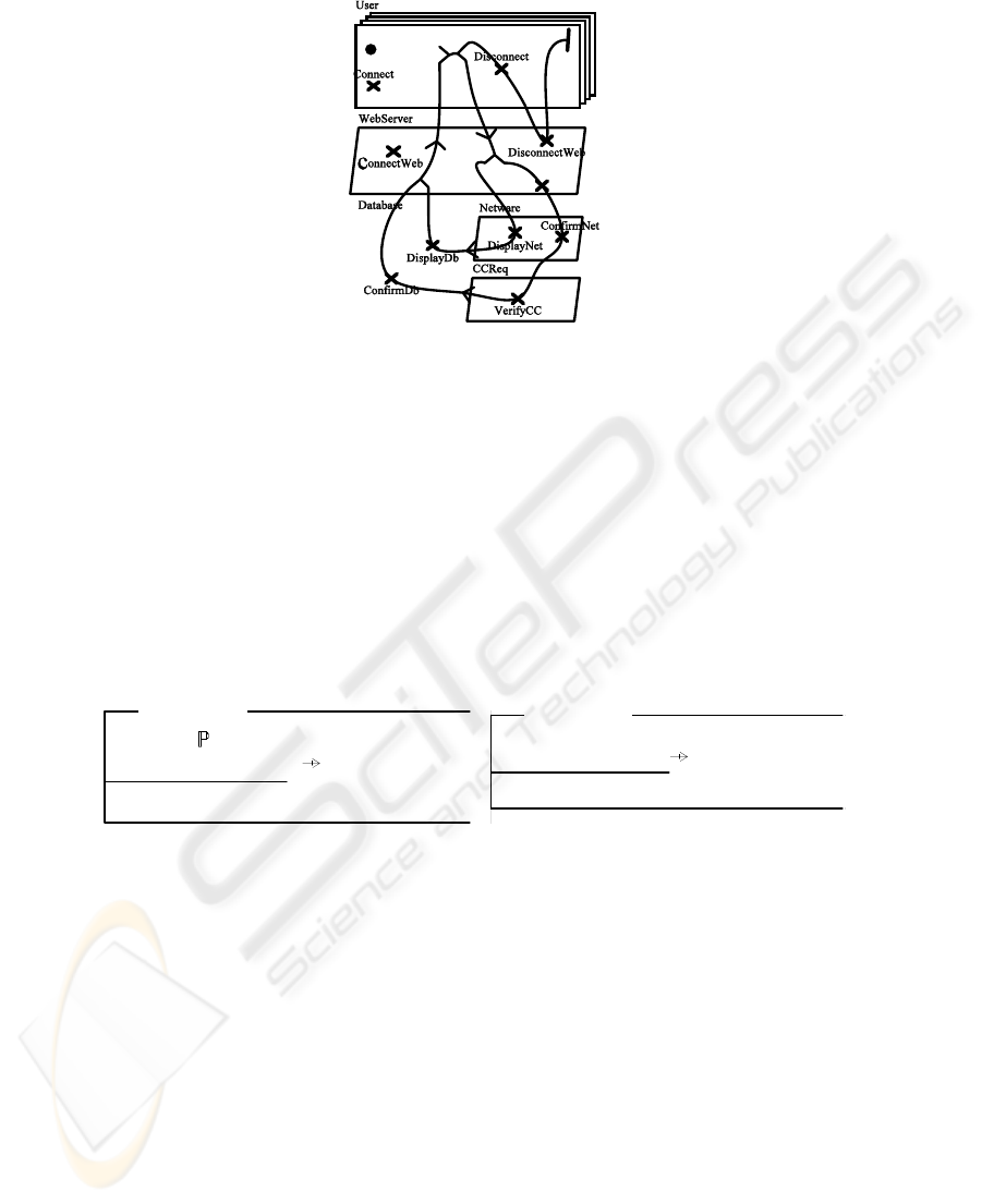
ConfirmWeb
Fig. 8. UCM for the TRS system.
5.1 Basic Types and State Spaces
Following Step 1 above reveals the basic types:
[USER, CONNECTION, SESSION].
USER represents all possible users, CONNECTION the set of all connections, and
SESSION the set of all possible sessions. Execution of Step 1 also identifies the
following 2 state schemas.
5.2 State Schemas
StateUsers
WebSessions: USER SESSION
dom webSession ⊆ dom usersConnected
StateWeb
listUsers: USER
usersConnected: USER CONNECTION
dom usersConnected ⊆ listUsers
StateUsers
The team component User in Fig. 8 controls the list of users and the list of
currently connected users. Only users known by the system can be connected. This
may help us to discover and consider new tasks such as the user registration process
and consequently rethink the UCM. The WebServer component controls the list of
open sessions, hence the inclusion of StateUsers in StateWeb above. Assuming a team
component for the system, we need to combine the two schemas, giving StateWeb.
We defer the initialisation of the system state to the definition of classes.
5.3 Partial Operations
Connect ; ConnectWeb ; ConfirmWeb (2)
10
Δ StateUsers
u?: USER
u? ∈ listUsers
c:CONNECTION • c ∉ ran usersConnected ∧
usersConnected ′ = usersConnected ∪ {u? → c}
Connect
Δ StateWeb
u?: USER
c?: CONNECTION
(u?, c?) ∈ usersConnected
s:SESSION
• webSessions ′ = webSession ∪ {u? → s}
ConnectWeb
Ξ StateWeb
u?: USER
s!: SESSION
rep!: RESPONSE
(u?,s!) ∈ webSessions
rep! = CONNECTED
ConfirmWeb
The schema calculus expression (2) shows the sequence in which the partial
operations are performed to accomplish the connection process. Formula (2) may be
expanded along the way to include more schemas and operators as the execution of
steps 1 and 2 above progresses.
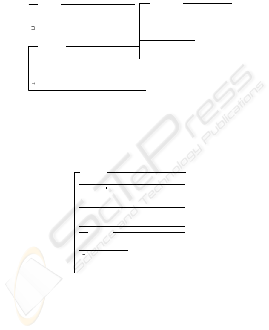
5.4 Definition of Classes
In the definition of classes, basic types are considered as empty classes with the same
name [21] as far as they represent undefined objects.
↑(usersConnected, Connect)
ClassUsers
listUsers: USER
usersConnected: USER × CONNECTION
dom usersConnected ⊆ listUsers
listUsers =
∅
usersConnected =
∅
INIT
Δ (usersConnected)
u?: USER
c:CONNECTION
• c ∉ ran (usersConnected) ∧
usersConnected’ = usersConnected
∪ {(u?,c)}
Connect
The execution of Step 2 above leads to the definition of 2 classes. ClassUsers is
derived from the UCM component User. It makes visible to the environment the state
variable usersConnected, and the operation Connect and includes the state schema
StateUsers. The state schema by convention does not have a name since there is only
one such schema in the definition of a class. INIT is the default name given to an
initial state.
RESPONSE ::= CONNECTED
11

WebSessions =
∅
INIT
↑(ConnectWeb, ConfirmWeb)
ClassUsers
ClassWebserver
webSessions: USER SESSION
dom webSession ⊆ dom usersConnected
Δ (webSessions)
u?: USER; c?: CONNECTION
(u?,c?) ∈ usersConnected
( s:SESSION)
•
webSessions ′ = webSessions
∪ {u? → c?}
ConnectWeb
u?: USER
s!: SESSION; rep!: RESPONSE
(u?,s!) ∈ webSessions
rep! = CONNECTED
ConfirmWeb
ClassWebserver inherits the list of the currently connected users from the class
ClassUsers. The state schema in this class includes only the component webSessions.
The other variable is accessible from inherited class. An invariant specifies that web
sessions are opened only to those users who have been successfully connected. The
two operations performed are ConnectWeb and ConfirmWeb. ConnectWeb changes
the state of the system whereas ConfirmWeb does not. In that case, the Δ list is
omitted. The Ξ convention is also not used in Object-Z.
6 Conclusions and Further Work
In this paper we proposed a framework to derive Object-Z class schemas from UCMs.
The map is first transformed into Z following a sequence of steps. We believe the
ability of Z to stimulate thorough thinking about system properties will aid the
transformation process towards Object-Z. This process has amongst others some
advantages: (i) It provides a flexible way to generate Z and Object-Z documents.
Formal reasoning is applied to manageable components of a UCM and not directly to
the whole system. (ii) Mathematical formulas can be used to facilitate traceability.
(iii) It may encourage the use of Z and Object-Z in industry. To this end a next step
would be to embark on empirical work in industry.
Although our approach has made an initial step towards the development of a
step-by-step construction process for Z and Object-Z from a UCM, further research is
needed to validate transformations and develop more cases aiming at discovering
additional transformational aspects of UCM. A comparison of our approach with
some others, e.g. transforming UCMs into Message Sequence Charts [18] should also
be conducted. A further aim may be to provide an iterative and interactive
12

environment for the construction of Z (object-Z) where a UCM serves as input and Z
is used to reveal possible errors in the UCM. Such a tool may provide for an
automated transformation of UCMs to Z (Object-Z).
References
1. Buhr, R.J.A., Use Case Maps as Architectural Entities for Complex Systems. Transaction
on Software Engineering, 1998: pp. 1131-1155.
2. Buhr, R.J.A. and Caselman, R.S.
Use Case Maps for Object-Oriented Systems. 1999, USA:
Prentice Hall.
3. Amyot, D.,
Use Case Maps: Quick Tutorial. 1999. http://jucmnav.softwareengineering.ca/
twiki/bin/view/UCM/VirLibTutorial99
4. Amyot, D. and Mussbacher, G.
URN: Toward a New Standard for the Visual Description of
Requirements.
E.Sherratt (Ed.) SAM 2002: pp. 21-37.
5. De Bruin, H. and Van Vliet, H.
Quality-Driven Software Architecture Composition. Journal
of Systems and Software 2003, 66(3), pp. 269-284
6. Amyot, D., Weiss, M. and Logrippo, L.
UCM-Based Generation of Test Goals. Computer
Networks, 2005, 49(5), pp. 643-660.
7. Buhr, R.J.A.,
Understanding Macroscopic Behaviour Patterns in Object-Oriented
Frameworks, with Use Case Maps.
1997. http://jucmnav.softwareengineering.ca/
twiki/bin/viewfile/UCM/VirLibUoof1997?rev=1.1;filename=uoof.pdf
8. Anna, M.,
Advanced Steps with Standardized Languages in the Re-engineering Process.
Computer Standards & Interfaces, 2008. 30(5): pp. 315-322.
9. Kealey, J. and Amyot, D.,
Enhanced Use Case Map Traversal Semantics, in SDL: Design
for Dependable Systems
. 2007, Springer Berlin / Heidelberg, pp. 133-149.
10. Potter, B., Sinclair, J and Till, D.
An Introduction to Formal Specification and Z. Second
ed. 1996: Prentice Hall International.
11. Lightfoot, D.,
Formal Specification Using Z. Second ed. 2001: Palgrave.
12. Sommerville, I.,
Software Engineering. Eighth ed. 2007: Addison-Wesley.
13. O'Regan, G.,
Mathematical Approaches to Software Quality. 2006: Springer.
14. Bowen, J.,
Formal Specification Documentation Using Z: A Case Study Approach. First ed.
1996: Thomson Computer Press.
15. Duke, R. and Rose, G.,
Formal Object-Oriented Specification using Object-Z. Second ed.
Cornerstones of Computing. R.B.Y.T. Hoare (Ed.) 2000.
16. Taibi, F., Jacob, K.D. and Fouad, M.A.,
On Checking the Consistency of Object-Z
Classes.
ACM 2007, 32 (4). Available online.
17. Smith, G.,
A Fully Abstract Semantics of Classes for Object-Z. Formal Aspect of
Computing, 1995 Vol 7: pp. 289-313.
18. Miga, A., Amyot, D., Bordeleau, F., Cameron, D., and Woodside, M.,
Deriving Message
Sequence Charts from Use Case Maps Scenario Specifications.
Tenth SDL Forum
(SDL'01), 2001: pp. 268-287.
19. Van der Poll, J.A. and Kotze, P.,
Enhancing the Established Strategy for Constructing a Z
Specification.
SACJ, 2005, No. 35: p. 118-131.
20. Van Der Poll, J. A., Kotze, P., Seffah, A., Radhakrishnan, T. and Alsumait, A.,
Combining
UCMs and Formal Methods for Representing and Checking the Validity of Scenarios as
User Requirements.
SAICSIT, 2003: pp. 111-113.
21. Periyasamy, K. and Mathew, C.,
Mapping a Functional Specification to an Object-Oriented
Specification in Software Re-engineering.
ACM, 1996: pp. 24-33.
22. Dorin, B. P. and Woodside, M.,
Software Performance Models from System Scenarios.
Springer Berlin/ Heidelberg, 2002. 2324/2002: pp. 1-8.
13
