
USING PASSAGES TO SUPPORT OFF-ROAD ROBOT NAVIGATION
Christopher Armbrust, Helge Sch
¨
afer and Karsten Berns
Robotics Research Lab, Department of Computer Sciences
University of Kaiserslautern
P.O. Box 3049, 67653 Kaiserslautern, Germany
Keywords:
Virtual sensors, Virtual sensor probes, Passages, Off-road navigation, Autonomy.
Abstract:
In this paper an approach for the detection of passages and their use in autonomous off-road robot navigation
is presented. The authors argue that many two-layered architectures of robot navigation systems suffer from
the gap between the typically coarse-grained high-level path-planning and the basically reactive low-level
collision avoidance. In this context, passages shall be defined as paths leading through obstacles. The proposed
approach is based on the idea that passages in the proximity to the robot should be evaluated with respect to
their relevance for reaching the target area in order to avoid local detours by following suitable passages.
The detection and assessment of passages is based on virtual sensors, a standardized data representation of-
fering a unified, straightforward, and flexible retrieval mechanism for accessing the data provided by different
sensor systems. For the evaluation of passages the authors introduce the concept of virtual sensor probes which
can move independently from the robot. That way the point of view on the environment information can be
tailored to support the detection and evaluation strategy.
The proposed approach was deployed on the mobile off-road platform RAVON which serves as a testbed for
the experiments carried out in the context of this work.
1 INTRODUCTION
Many robot navigation systems are designed follow-
ing a two-layer concept: A deliberative path-planner,
the “navigator”, builds global maps, which it uses for
high-level path planning. The output of this planner
are single path points, which are passed to a lower
level component, the “pilot”. This component trans-
forms the target coordinates into motion commands,
taking into account sensor data to realize collision
avoidance. The pilot typically operates in a nearly
reactive way, storing only little state information and
having a very much limited view on the robot’s en-
vironment. In such an architecture, the pilot exerts
a draw towards the target, which the anti-collision
system may counteract, resulting in the robot driving
around obstacles towards the target.
While this principle works well in simple envi-
ronments, it can easily fail in more complex ter-
rain. As the collision-avoidance works locally, miss-
ing the “big picture”, it cannot keep the navigator
from drawing the robot away from a path and into
small openings between obstacles, which are so wide
Figure 1: The problem of dealing with indentations.
that the collision avoidance does not get active di-
rectly, but which could be easily recognized as inden-
tations when using a larger scope (see Figure 1, (1)).
The idea that is presented here is to search for
paths leading through obstacles, so-called passages,
and to evaluate them with respect to their value for the
robot’s navigation. In the described situation, the path
the robot is driving on would be detected as such a
189
Armbrust C., Schäfer H. and Berns K. (2009).
USING PASSAGES TO SUPPORT OFF-ROAD ROBOT NAVIGATION.
In Proceedings of the 6th International Conference on Informatics in Control, Automation and Robotics - Robotics and Automation, pages 189-194
DOI: 10.5220/0002198501890194
Copyright
c
SciTePress

passage, while the indentation would be ignored (see
Figure 1, (2)). Furthermore, estimating a passage’s
orientation would allow for directing the robot in a
way that it can more easily enter the passage.
It shall be emphasized here that the described ap-
proach targets at environments in which there is no
clear path that could be followed using a path track-
ing approach like the ones mentioned in section 2. In-
stead, the paths constituted by passages are consecu-
tive spaces between obstacles that are wide enough to
be used by a robot.
2 STATE OF THE ART
The concept of separating a robot navigation system
into two layers is widespread and described in many
places in the literature. The classic separation results
in a low-level system for local navigation that has a
limited view on the world and operates in a fast, yet
shortsighted manner. Different approaches have been
followed to establish the interaction of the two parts
((Wooden et al., 2007), (Ranganathan and Koenig,
2003)). An approach for detecting narrow passages in
indoor environments is described in (Schr
¨
oter, 2005).
Its author used the polar data of a laser scanner to
identify and assess passages and combined it with 3D
rectangular objects reconstructed from the images of a
stereo vision system to identify doors. The algorithm
used for processing the laser data resembles the one
presented here. However, it only processes the data
of one polar sensor and not of several (virtual) sen-
sors. Evidently, using a stereo system in such a way to
detect passages will not work in unstructured off-road
environments. Approaches for keeping the robot from
leaving the road or path include detecting curbs using
a light-stripe scanner (Thorpe et al., 2003), detecting
lanes using edge extraction from images, or road de-
tection using a combination of LADAR data and color
information (Hong et al., 2002). The work described
in (Lieb et al., 2005) uses the assumption that the ve-
hicle is situated on the road to form templates of the
road’s appearance and from them and current images
calculates an estimate of the road’s curvature. (Alon
et al., 2006) describes a system that uses two different
path-finding algorithms in parallel and uses the output
of the one with the highest confidence. However, all
of these approaches are tailored to detecting a path in
an environment that is completely different from the
one of this work.
3 SYSTEM ARCHITECTURE
3.1 A Two-layered Navigation System
The work at hand is embedded into a two-layered
robot navigation system consisting of a classical
deliberative navigator (Braun and Berns, 2008) on
top of a behavior-based system for local navigation,
i.e. target-oriented motion and collision avoidance
(Sch
¨
afer et al., 2008b). The navigator creates and up-
dates topological maps of the environment, which are
used as basis for the path planning process. It sends
the points of a path one by one to the lower layer, from
which it receives basic status information.
3.2 Virtual Sensors
Special behaviors of the local navigation system
translate the goal poses into motion commands, which
are altered by a behaviour-based anti-collision sys-
tem. The behaviors use a special type of representa-
tion that provides a powerful yet slim interface to ar-
bitrary types of sensors. Different aspects and ranges
of the robot’s environment are abstracted using po-
lar and Cartesian sector maps, which represent virtual
sensors (VS). Polar maps are defined by start and stop
angles whereas Cartesian maps have an extent in pos-
itive and negative y-direction. Each sector holds the
most relevant representative of the area it covers. In
the architecture presented here, the VS are filled with
data from a scrollable, robot-local, and orientation-
fixed grid map that stores highly preprocessed sensor
data of a pannable laser range finder (Sch
¨
afer et al.,
2008a). Using this short-range map as input for the
virtual sensors allows for monitoring areas which are
currently not in the range of the robot’s real sensors.
3.3 Virtual Sensor Probes
While the virtual sensors used for collision avoid-
ance are defined with respect to the robot coordinate
system (RCS) and are fixedly mounted on the robot,
virtual sensors that are used to gather information
about specific structures in the environment have to
be fix with respect to the working coordinate system
(WCS). Hence their pose in terms of the RCS changes
whenever the robot moves. This special type of vir-
tual sensor is called virtual sensor probe (VSP).
The preprocessing of the sensor data, the coordi-
nate transformations (sensor to robot to working CS),
and the filling of the VSPs with the correct data is
done in the sensor processing subsystem. Therefore
higher components do not have to deal with these
technical details, but can simply provide a WCS pose
ICINCO 2009 - 6th International Conference on Informatics in Control, Automation and Robotics
190

Figure 2: The views of a real sensor and a virtual sensor
probe.
for a VSP and be assured that it is filled with the cor-
rect information.
Using VSPs, the robot can “look” at a place in
the environment from a different point of view (see
Figure 2). While this naturally does not yield new
information that the robot cannot gather from its ac-
tual pose, it structures the existing sensor data in an
abstract way, allowing for the use of more straightfor-
ward algorithms.
4 THE USE OF PASSAGES
4.1 Passage Detection
A passage is defined by its entry, which is delimited
by an obstacle on each side. These two obstacles are
called Passage Entry Points (PEP), the line connect-
ing them Passage Entry Line (PEL). The algorithm
for detecting passages traverses all sectors s
i
of a po-
lar sector map (see Figure 3, (1)) covering the area in
front of the robot and compares the distances d
i
of the
obstacles o
i
(with 0 ≤ i < n and n being the number
of sectors).
If o
j+1
is farther away from the origin than o
j
by
at least the threshold t
0
, then o
j
is considered as po-
tential first PEP. Be o
k
with k ≥ j +1 the first obstacle
that is closer to the origin than o
j+1
by at least the
threshold t
1
. Then o
k
is the second PEP and all ob-
stacles between o
j
and o
k
are considered to lie within
the passage. The new passage is added to a list and
the search goes on with the remaining sectors. In the
following, pseudocode for the detection algorithm is
shown.
For every passage, the passage entry midpoint
(PEMP), which is defined as the point lying in the
middle between o
j
and o
k
, is calculated. It is a pas-
sage’s characteristic point and, as described below, is
important for navigating into a passage.
As the distance values in the sectors refer to
the virtual sensor’s coordinate system, the algorithm
Algorithm 1. Detecting Passages.
searching for = cFIRST PEP; // the status of the search process
index first pep = 0; // the first PEP’s index
index point in passage = 0; // the index of a point within the passage
for (i = 0; i < n - 1; i++) do
if (searching for = cFIRST PEP) then
if (d[i] - d[index first pep] < t 0) then
index first pep = i;
else
searching for = cSECOND PEP; index point in passage = i;
else // currently searching for second PEP
if (d[index point in passage] - d[i] >= t 1) then
passages.add(new Passage(o[index first pep], o[i]);
index first pep = i;
searching for = cFIRST PEP;
else
// nothing to be done here
Figure 3: The sector maps used for passage detection.
tends to not detect passages that lie in the sideway
parts of the polar sector map. To overcome this de-
ficiency, two Cartesian sector maps are also used as
data sources (see Figure 3, (2)). Due to the generic
interface of the sector maps, the algorithm described
above needs only simple modifications to process the
data of Cartesian sector maps.
It shall be remarked here that by using sector
maps, the passage detection and evaluation algo-
rithms do not have to access the complex grid map,
but can operate on a much simpler data structure.
A temporal aspect was integrated by creating and
updating a list of persistent passages: In every sen-
sor processing cycle, the PEMP of each passage that
is detected is compared to the PEMP of each persis-
tent passage. Two passages are regarded as similar if
the distance between their PEMPs is below a certain
threshold. Taking into account the passages’ PEPs
was also considered, but experiments showed that the
distance between two PEMPs is a suitable criterion
for similarity. If a similar persistent passage is found,
it is updated with the newly found passage, i.e. the
persistent passage’s PEPs and PEMP are set to the
ones of the new passage. If not, the newly found pas-
sage is added to the list of persistent passage. Per-
sistent passages that have not been seen for a certain
amount of time are removed.
USING PASSAGES TO SUPPORT OFF-ROAD ROBOT NAVIGATION
191

4.2 Passage Evaluation
The passage evaluation operates on the persistent pas-
sages. Its first step checks whether a passage fulfills
the basic requirements, i.e. whether it is wide enough,
has a minimum age, lies in a suitable direction, has
a suitable orientation, and is long enough. A pas-
sage which fulfills these requirements is called suit-
able passage.
The first four aspects can be checked easily. A
passage’s width is calculated as the distance between
its two PEPs. If a passage’s entry is too narrow for the
robot, it is obviously irrelevant for navigation. The
age is calculated as time that has passed between the
first and the latest detection. Passages which have not
been seen for a minimum amount of time are ignored.
As passages shall be used to assist the navigation
system in driving the robot to its target, a suitable pas-
sage shall lie in the direction of the target with respect
to the robot. This is checked by comparing the ori-
entation of two lines—one going from the robot to
the target and one going from the robot to the PEMP.
Furthermore, a suitable passage has to point approxi-
mately in the direction of the target. This is checked
by first calculating the orientation of a line that starts
at the PEMP and is perpendicular to the PEL. This ori-
entation is then compared to the one of a line starting
at the PEMP and going to the target. If the difference
between the two orientations is below a certain thresh-
old, the passage is considered to be well-oriented.
A VSP represented by a Cartesian sector map con-
sisting of only one sector is used to “look” into the
passage, measure the distance to the closest obstacle
and thus estimate the passage’s length (see Figure 4,
(1)). Using a sector map as VSP instead of accessing
the grid map directly facilitates the data access and
spares the evaluation component more complex data
processing.
Figure 4: The sector maps for length and orientation esti-
mation.
It is advisable to navigate the robot in a way that
it reaches the PEMP with approximately the passage’s
orientation as this facilitates entering the passage. The
orientation estimation described above does not take
into account information about the presence of obsta-
cles in the passage. Thus a more precise estimate is
calculated for the passage that best satisfies the above
criteria, the relevant passage. Two Cartesian sector
maps are used to monitor the sides of the passage (see
Figure 4, (2)). Each of their sectors stores informa-
tion about the closest obstacle in the area it covers, i.e.
it contains a local estimate of how far away the pas-
sage’s border is. For each sector, the angle between
the following two lines is calculated: (a) a line that
starts at the PEMP, is perpendicular to the PEL and
points into the passage, and (b) a line going from the
PEMP to the sector’s obstacle. The passage’s orien-
tation is calculated from the arithmetic mean of these
angles, so its axis is pushed away from obstacles (see
Figure 4, (3)). Of course this is only a rough esti-
mate, but it can be calculated using the existing mech-
anisms, while other methods need more complex, spe-
cialized algorithms.
4.3 Integration
The component that detects and evaluates passages
and navigates the robot to a PEMP has been imple-
mented as behavior and integrated into the behavior-
based system mentioned above. It is referred to as
passage behavior. Whenever it detects a relevant pas-
sage, it gets active and sends the coordinates of the
PEMP to the behaviors that drive the robot to given
target coordinates. These behaviors are also used by
the navigator, but when a passage is detected, the be-
havior gets active and overwrites the target pose pro-
vided by the navigator.
In some cases, an inhibition of the passage behav-
ior is sensible. If the robot follows a wide path that
leads to the target and has only few obstacles, the pas-
sage behavior would constantly detect a relevant pas-
sage and would try to guide the robot to its PEMP. If
the number of visible obstacles is too low, the orienta-
tion calculations would produce poor estimates. Us-
ing these passages would result in a swinging robot
motion although it would be possible to drive straight
ahead. To cope with this problem, another behavior
uses a wide Cartesian sector map to monitor the area
in the direction of the target. If there is no obstacle,
there is no need for using passages, so the monitor-
ing behavior inhibits the passage behavior and thus
returns control to the navigator.
The system’s operation shall be illustrated taking
up the example from section 1. At first, only a small
part of the situation is visible to the robot (see Fig-
ure 5, (1)). A large passage is detected between the
outer obstacles. The area in the direction of the target
(green square) is free, so the passage is ignored. As
soon as the free space to the right of the robot is rec-
ognized as indentation, the navigation system guides
ICINCO 2009 - 6th International Conference on Informatics in Control, Automation and Robotics
192
the robot towards the newly detected suitable passage
instead of driving into the indentation (see Figures 5,
(2) and (3)).
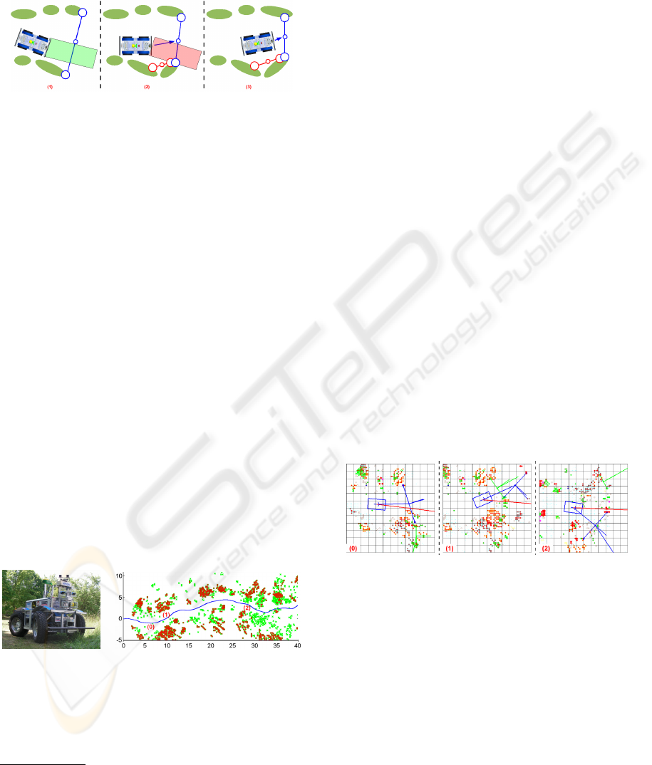
Figure 5: The operation of the passage behavior in the situ-
ation depicted in Figure 1.
5 EXPERIMENT AND RESULTS
For experiments the passage detection mechanism
presented in this paper was integrated into the nav-
igation software of the mobile off-road platform
RAVON
1
, a 4WD vehicle with the dimensions and
weight of a city car, which is equipped with a variety
of sensor systems (e.g. 2D laser scanners, a 3D laser
scanner, stereo camera systems). Detailed informa-
tion about the robot can be found in (Armbrust et al.,
2009).
Several test runs have been conducted in the
Palatinate forest, of which one shall be presented here
as example
2
. RAVON started on a trail and was given
a target location several hundred meters away. Its task
was to drive there fully autonomously. Figure 7 shows
a part of the run as pose trace. Red crosses symbolize
obstacles that were classified by the sensor process-
ing system as definitely not traversable. Vegetation
that was probably traversable when driving cautiously
is marked with green crosses. It shall be pointed out
here that the robot drove the complete route depicted
in the figure without any user action.
Figure 6: RAVON.
Figure 7: The pose trace with the
checkpoints. The unit of length is
meter.
Different passages were detected during the drive.
For lack of space, only three significant checkpoints
1
Ravon: Robust Autonomous Vehicle for Off-road Nav-
igation
2
video showing large part of test available at:
http://rrlab.cs.uni-kl.de/robot-gallery/ravon/
shall serve as examples here. For each of them, a visu-
alization of the scrollable grid map filled with the 3D
scanner’s data is depicted (see Figure 8). The robot
is situated in the map’s center (blue square). The col-
ored circles depict various types of obstacles (red: too
high to be driven over; green: other types of obstacles
with ground contact; pink: places where the robot
could hit the ground). The direction to the target is
visualized by a red line starting at the robot’s center.
Passages are visualized with circles for the PEPs and
PEMPs, and lines for the PEL and for visualizing the
first and second orientation estimates. For reasons of
clarity, only two types of passages are displayed: suit-
able, but not relevant ones (green), and relevant ones
(blue).
Shortly after the start, at checkpoint 0, the path
made a slight turn to the left. The relevant passage
was oriented to the left, following the path (see Fig-
ure 8, (0)). Although it did not lie exactly in the direc-
tion of the target and was oriented a bit away from it,
it was still suitable. While this was a good first exam-
ple of the passage behavior’s operation, the combined
action of the navigator and the anti-collision system
would most likely have dragged the robot around the
obstacles to its right.
At checkpoint 1 (see Figure 8, (1)), the deviation
of the path’s direction from the direction to the target
was so large that following the navigator’s drag would
have led the robot into the underwood. The usage of
the passage along with its orientation resulted in the
robot driving a curve around the obstacles to its right.
Figure 8: The situation at the three checkpoints.
At the last checkpoint (see Figure 8, (2)), the
robot’s motion would have probably been the follow-
ing without the use of the passage: When driving to-
wards the target, the robot would have gotten so close
to the obstacles ahead of it that the collision avoid-
ance behaviors would have had to turn it to the left
or the right. Due to noisy sensor data and the lack
of a larger scope, it is possible that the robot would
have been turned to the left, thus driving straight into
the underwood. At this point, backing off maneuvers
would have to be conducted. By contrast, the detec-
tion of a suitable passage made the robot turn to the
right. It avoided the obstacles before getting too close
to them and stayed on the trail. Due to the obstacles
USING PASSAGES TO SUPPORT OFF-ROAD ROBOT NAVIGATION
193

on the left border of the trail, no suitable passage was
detected there—which is the desired behavior of the
detection component.
6 CONCLUSIONS AND FUTURE
WORKS
In this paper a concept for passage detection tai-
lored to navigation in terrain with many obstacles and
without a clear path was presented. Furthermore, a
loosely coupled interaction of the passage detection
facility with a topological navigator on the basis of
passage orientation estimation was proposed. A suit-
able passage is negotiated by continuously passing the
characteristic passage entry midpoint to a behavior-
based point approacher. That way non-holonomic
platforms—as presented in the experiments by exam-
ple of the off-road robot RAVON—can enter even nar-
row passages without unneeded maneuvering.
The presented system is capable of leading the
robot through complex terrain on the basis of a sin-
gle target location avoiding local detours where pos-
sible. As only local terrain information is available
on this layer, difficulties like dead ends still remain a
problem. As a next step, the passage behavior shall
provide detected passages to the navigator, which
shall store them in terms of navigation-relevant spots.
When a dead end is reached, the navigator shall tag
passages leading to the current location as dead end
entry points to avoid global detours in the future.
Furthermore, the system shall be extended so that
other types of navigation-relevant places like very
narrow ways (which require especially careful move-
ments) or crossroads (which offer several options for
the robot to proceed to the target area) are also de-
tected. Exchanging information about these places
with the higher navigation layer will support back-
tracking if following a path turns out to be unhelpful
in getting to the target.
ACKNOWLEDGEMENTS
Team RAVON thanks the following companies for
their technical and financial support: IK elektronik,
Mayser, Hankook, MiniTec, SICK, DSM Computer,
H
¨
ubner Giessen, John Deere, Optima, ITT Cannon,
MOBOTIX, and Unitek.
REFERENCES
Alon, Y., Ferencz, A., and Shashua, A. (2006). Off-road
path following using region classification and geomet-
ric projection constraints. In Proceedings of the 2006
IEEE Computer Society Conference on Computer Vi-
sion and Pattern Recognition, volume 1, pages 689–
696, New York, NY, USA. IEEE Computer Society
(Washington, DC, USA).
Armbrust, C., Braun, T., F
¨
ohst, T., Proetzsch, M., Renner,
A., Sch
¨
afer, B., and Berns, K. (2009). Ravon — the
robust autonomous vehicle for off-road navigation. In
Proceedings of the IARP International Workshop on
Robotics for Risky Interventions and Environmental
Surveillance 2009 (RISE 2009), Brussels, Belgium.
IARP.
Braun, T. and Berns, K. (2008). Topological edge cost es-
timation through spatio-temporal integration of low-
level behaviour assessments. In Proceedings of
the 10th International Conference on Intelligent Au-
tonomous Systems (IAS-10), Baden Baden, Germany.
Hong, T.-H., Rasmussen, C., Chang, T., and Shneier, M.
(2002). Road detection and tracking for autonomous
mobile robots. In Proceedings of SPIE Aerosense
Conference, Orlando, FL, USA.
Lieb, D., Lookingbill, A., and Thrun, S. (2005). Adaptive
road following using self-supervised learning and re-
verse optical flow. In Robotics: Science and Systems,
pages 273–280, Cambridge, Massachusetts, USA.
Ranganathan, A. and Koenig, S. (2003). A reactive robot
architecture with planning on demand. In Proceed-
ings of the 2003 IEEE/RSJ International Conference
on Intelligent Robots and Systems, pages 1462–1468,
Las Vegas, Nevada, USA.
Sch
¨
afer, H., Hach, A., Proetzsch, M., and Berns, K.
(2008a). 3d obstacle detection and avoidance in veg-
etated off-road terrain. In IEEE International Confer-
ence on Robotics and Automation (ICRA), pages 923–
928, Pasadena, USA.
Sch
¨
afer, H., Proetzsch, M., and Berns, K. (2008b).
Action/perception-oriented robot software design: An
application in off-road terrain. In IEEE 10th Interna-
tional Conference on Control, Automation, Robotics
and Vision (ICARCV), Hanoi, Vietnam.
Schr
¨
oter, D. (2005). Region & Gateway Mapping: Ac-
quiring Structured and Object-Oriented Representa-
tions of Indoor Environments. PhD thesis, Institut
f
¨
ur Informatik der Technischen Universit
¨
at M
¨
unchen,
M
¨
unchen, Germany.
Thorpe, C., Carlson, J., Duggins, D., Gowdy, J., MacLach-
lan, R., Mertz, C., Suppe, A., and Wang, B. (2003).
Safe robot driving in cluttered environments. In 11th
International Symposium of Robotics Research, Siena,
Italy.
Wooden, D., Powers, M., MacKenzie, D., Balch, T., and
Egerstedt, M. (2007). Control-driven mapping and
planning. In Proceedings of the 2007 IEEE/RSJ In-
ternational Conference on Intelligent Robots and Sys-
tems, pages 3056–3061, San Diego, CA, USA.
ICINCO 2009 - 6th International Conference on Informatics in Control, Automation and Robotics
194
