
FUZZY TRAJECTORY TRACKING FOR AN AUTONOMOUS
MOBILE ROBOT
Carlos Fernández Caramés, Vidal Moreno Rodilla
Departamento de Informática y Automática, University of Salamanca, Plaza de los Caídos S/N, Salamanca, Spain
Belén Curto Diego, José Andrés Vicente Lober
Departamento de Informática y Automática, University of Salamanca, Plaza de los Caídos S/N, Salamanca, Spain
Keywords: Mobile robot, Heading sensor, Fuzzy controller.
Abstract: This paper proposes a fuzzy controller embedded in a closed-loop control system designed to make a robot
track a straight line. The system uses a heading sensor to measure the error in the orientation of the robot. A
real robot is simulated in Matlab so as to test and accelerate the development process of the fuzzy controller.
Finally, experimental results of the simulated and the real robot are presented, showing the effectiveness of
our approach under strong disturbances such as unexpected robot rotations.
1 INTRODUCTION
There is no doubt whatsoever that moving from one
place to another is a must for every mobile robot.
The type of movements that a robot will perform
will nonetheless be different depending on if it is
familiarized with its surroundings or not. When a ro-
bot is exploring an unknown environment, it will
typically wander aimlessly either trying to build a
map, trying to locate itself, or both things at the
same time. However, when a robot is within a
previously known environment, its movements will
generally be planned by a high level path planner,
provided that a map is available.
Path planning, together with map building and
localization, is one of the three fundamental tasks a
robot has to master to fully solve the navigation
problem, and it is the area of navigation which has
received the most attention (Murphy, 2000). The
path planning problem consists in designing a path
between an initial position and a target position such
that (a) the robot does not collide with any static or
dynamic obstacles in the environment and (b) the
planned motion is consistent with the kinematic
constraints of the vehicle (Zou et al., 2006). The
kinematics of a vehicle are determined by the
steering mechanism, being differential drive and
Ackermann drive two of the most frequently used
steering mechanisms for mobile robots.
There are many different approaches to path
planning, both for differential and for Ackermann
steered robots, but in the end, the final result of any
path planner is a sequence of path segments (Baltes
and Hildreth, 2001). Many planners use a sequence
where each segment is either a straight line, a full
left turn or a full right turn, based on the early work
of Reeds and Shepp (Reeds and Sheep, 1990), which
proves that the shortest path for any vehicle can be
planned using exclusively these three types of
segments.
Once the path is planned, the robot should be
able to follow the planned segments as accurately as
possible. The aforementioned maneuvers —straight
lines and full turns— may seem easy to perform by a
human driver with some experience, but they are not
straightforward at all for an autonomous mobile
robot. Tracking a straight line is somewhat difficult
than tracking full turns, and this is particularly true
for a differential drive robot. Moving the wheels of a
differential robot at the very same speed is not
enough to achieve a straight line, because different
wheel radii or wheel slippage, among other reasons
(see (Borenstein et al., 1996)), will cause the robot
to get out of its intended trajectory sooner or later.
Ackermann steered robots, although more robust for
straight line tracking than differential steered robots,
are also difficult to be driven along a straight line.
359
Fernández Caramés C., Moreno Rodilla V., Curto Diego B. and Andrés Vicente Lober J. (2009).
FUZZY TRAJECTORY TRACKING FOR AN AUTONOMOUS MOBILE ROBOT.
In Proceedings of the 6th International Conference on Informatics in Control, Automation and Robotics - Intelligent Control Systems and Optimization,
pages 359-362
DOI: 10.5220/0002198603590362
Copyright
c
SciTePress
For example, in our robotics research group we own
an unmanned forklift truck (reverse Ackermann
steering), whose main difficulty is that it has a high
degree of looseness in its steering wheel.
The conventional approach for controlling these
robots and make them follow a straight line would
be to design a PID (Proportional, Integral and
Derivative) controller. Consequently, we would need
to know every physical detail about the robot and its
environment so as to be able to model such a system
mathematically (Marzi, 2006). However, we humans
do not need accurate information from the
environment or from a vehicle to control it and
perform successful maneuvers. Most of the time we
deal with approximate reasoning rather than precise,
and it can be expressed linguistically by a series of
if-then rules. Luckily, this rationale is not only
available humans, since fuzzy logic provides us with
a mathematical framework to translate our linguistic
expert knowledge into numerical data which can be
used by robots.
In this paper we present a fuzzy approach to
solve the problem of straight line tracking for
differential robots using an Attitude and Heading
Reference System (AHRS).
2 GENERAL SYSTEM
DESCRIPTION
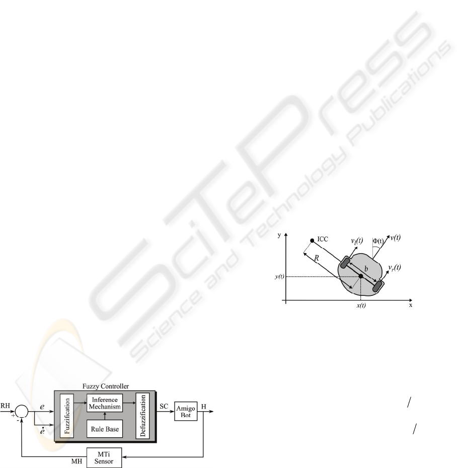
The general block diagram of our system is depicted
in Fig. 1, which shows a fuzzy controller embedded
in a closed-loop control system. The system works
by selecting a reference heading (RH), which the
robot will have to follow. Then, the MTi sensor
measures the heading (MH) of our robot
(AmigoBot). The difference between this two data is
used to calculate the heading error (e) and its
derivative (ė). Next, these data are used as the inputs
of the fuzzy controller, which determines the change
in speed (SC) needed to correct the heading (H) of
the robot.
Figure 1: General system description.
The core of the system is the fuzzy controller,
which consists of four components: (1) the “rule
base” is the set of rules that control the system. (2)
The inference mechanism evaluates which control
rules are relevant. (3) The fuzzification interface
modifies the inputs to the fuzzy controller so that
they can be interpreted and compared to the rules in
the rule base. (4) The defuzzification interface
transforms the conclusions reached by the inference
mechanism into the input to the robot.
The MTi is a low-cost Attitude and Heading
Reference System (AHRS) from Xsens
technologies. We use it to measure the heading angle
of the robot. The mobile robot we have chosen is the
AmigoBot from MobileRobots Inc.
3 KINEMATIC MODEL OF THE
ROBOT
The kinematic model of the AmigoBot is depicted in
Fig. 2. There, ICC stands for Instantaneous Center of
Curvature; v
l
(t) and v
r
(t) are the linear velocity of the
left and right wheel; R is the curvature radius
described by the middle point of the wheel axis, and
b is the distance between wheels. When the linear
velocities of the left and right wheel are different,
the robot turns around the ICC with angular velocity
w(t).
Figure 2: Kinematic model of the Amigobot.
Additionally, if we designate R
l
and R
r
as the
curvature radii described by the left and the right
wheel, respectively, then R = (R
l
+ R
r
)/2. Taking
this into account, and the fact that v
l
(t) = w(t)·R
l
and
v
r
(t) = w(t)·R
r
, the linear velocity of the robot can be
expressed as
()
2)()()()( tvtvRtwtv
lr
+
=
=
. If we
continue developing, we can obtain the angular
velocity of the robot as
()
btvtvtw
lr
)()()( −= .
The state of the robot is represented by the
variables x(t), y(t) and Φ(t)
, and it can be obtained
by integrating (1). We use it to study the
performance of the robot in a simulated
environment.
ICINCO 2009 - 6th International Conference on Informatics in Control, Automation and Robotics
360
()
()
⎥
⎦
⎤
⎢
⎣
⎡
⎥
⎥
⎥
⎦
⎤
⎢
⎢
⎢
⎣
⎡
=
⎥
⎥
⎥
⎦
⎤
⎢
⎢
⎢
⎣
⎡
)(
)(
10
0)(cos
0)(sin
)(
)(
)(
tw
tv
t
t
t
ty
tx
φ
φ
φ
(1)
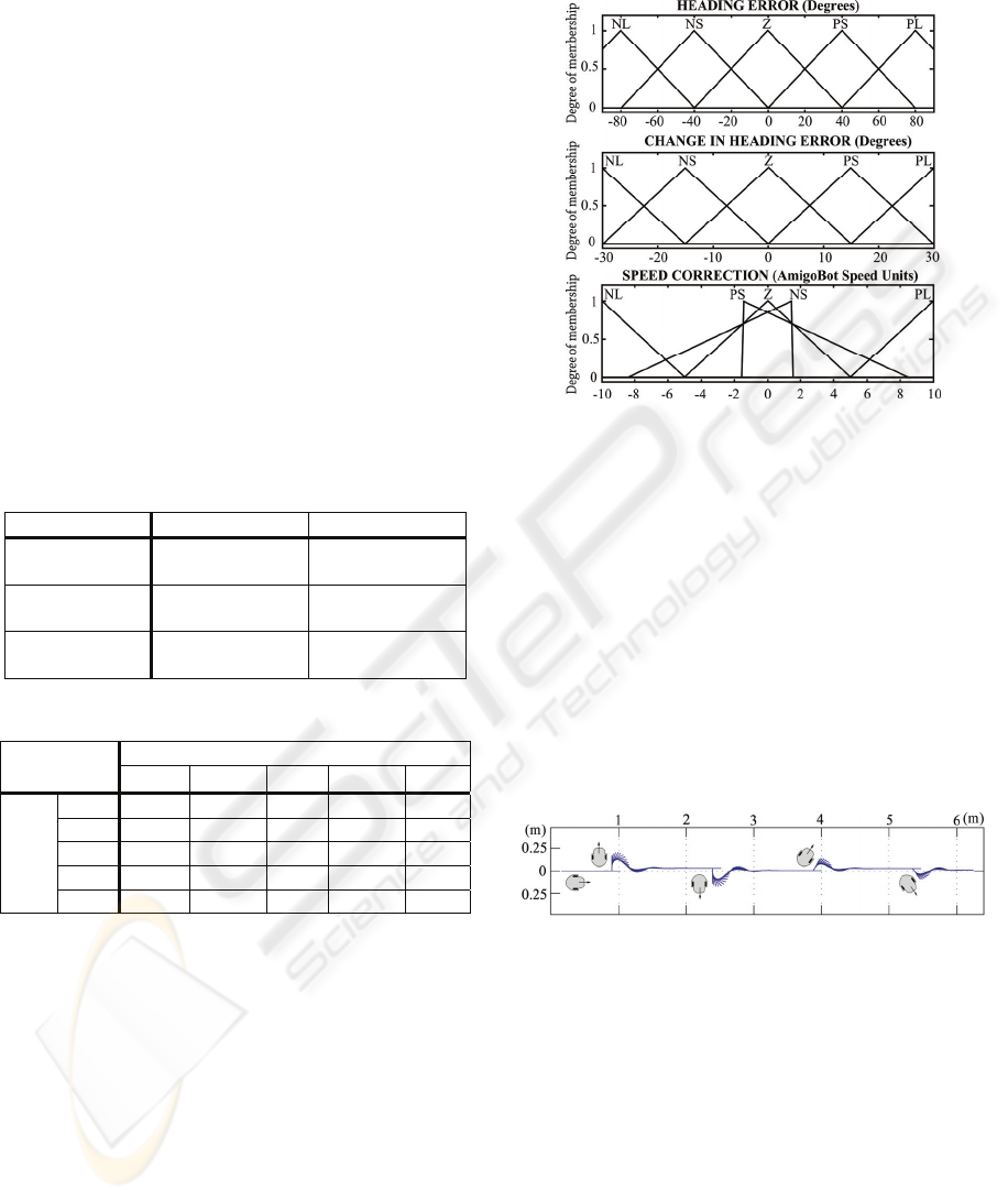
4 FUZZY LOGIC CONTROLLER
The definition of a fuzzy system can be broken
down in several parts (Passino and Yurkovich,
1998): a) variables and values, b) rule set and c)
membership functions.
We have used three linguistic variables: “heading
error”, “change in heading error” and “speed
correction”, and 5 different linguistic values for each
variable: NL (negative large), NS (negative small), Z
(zero), PS (positive small) and PL (positive large).
The way these terms are used is indicated in Table 1,
where CW and CCW stand for clockwise and
counterclockwise, respectively.
Table 1: Meaning of the linguistic terms.
Positive Negative
Heading error Robot is rotated
CCW
Robot is rotated
CW
Change in
heading error
Robot is rotating
CCW
Robot is rotating
CW
Speed
Correction
Robot needs to
rotate CCW
Robot needs to
rotate CW
Table 2: Rule table for the Amigobot.
Speed
Correction
Change in heading error (
ė)
NL NS Z PS PL
Heading
error
(
e
)
NL PL PL PL PS Z
NS PL PL PS Z NS
Z PL PS Z NS NL
PS PS Z NS NL NL
PL Z NS NL NL NL
Using the linguistic quantification stated in the
previous subsection, we have designed a set of rules
(see Table 2) that describe how to make the robot
follow a straight line. Finally, the membership
functions of the system are depicted in Fig. 3.
Because of a hardware limitation, the linear
speed of the Amigobot wheels can only be set to
multiples of 20 mm/s. Thus, we have designed the
membership function of the speed correction
variable taking into account this peculiarity, and
hence each unit in the x axis means 20 mm/s. Once
the fuzzy system computes an output speed
correction, this value is added to the current right
wheel speed and subtracted from the current left
wheel speed. Thus, the required torque is achieved
and the robot rotates toward the desired direction
while the linear speed remains constant.
Figure 3: Membership functions.
5 EXPERIMENTAL RESULTS
We have simulated the movements of AmigoBot
using the kinematic model (1) and the readings from
the heading sensor, where we have added random
white noise to mimic the specifications of the MTi
unit. The simulation results were very similar to the
real world results, and therefore, we only show the
performance of the real robot. During the tests, the
robot was commanded to travel at a constant speed
of 0.2 m/s, and it was subjected to four strong
disturbances of ≈-90º, ≈90º, ≈-45º and ≈45º.
Figure 4: Simulated robot trajectory.
An illustration of the trajectory followed by the
robot is shown in Fig. 4, where the robot is
represented as a short segment. Next to each
deliberated turn, the robot is depicted. The
corresponding input and output variables for the
simulation of the fuzzy system are shown in Fig. 5.
As it can be seen, the robot gets stabilized quickly
and smoothly after the unexpected rotations. When
the robot is subjected to 45º turns, it offers fast
response times (it is stabilized in 1s) and excellent
performance: it does not virtually oscillate at all. On
the other hand, when it is presented with strong
disturbances (90º turns approximately), its response
FUZZY TRAJECTORY TRACKING FOR AN AUTONOMOUS MOBILE ROBOT
361
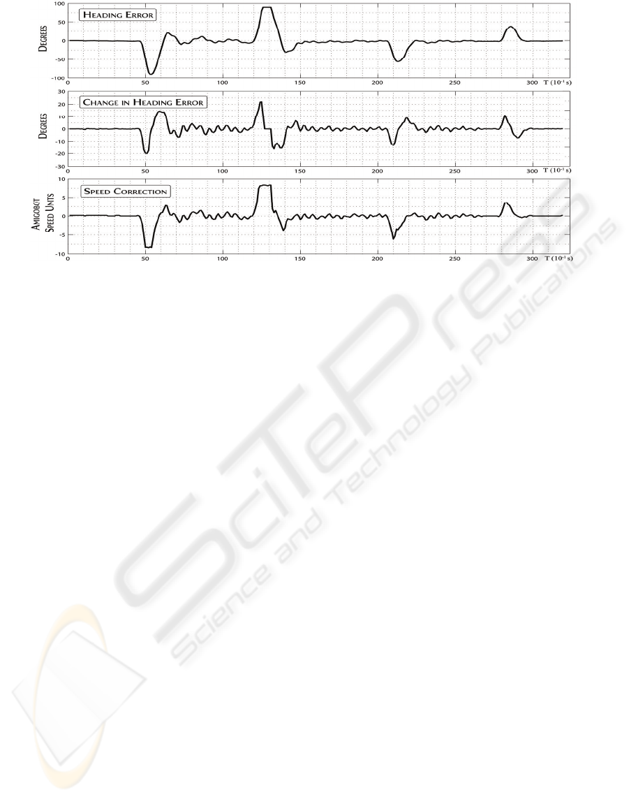
Figure 5: Real robot experimental results.
is still acceptable although the heading takes more
time (2-3 s) to get stabilized because of oscillation.
6 CONCLUSIONS
Path planners are widely used when a mobile robot
is within a known environment. Many path planning
methods give as a result a sequence of straight line
segments and full turns, because it has been proved
that the shortest path between two points can be
achieved that way. Taking into account that full
turns are less difficult to perform, we have proposed
and implemented a fuzzy controller that is capable
of following straight lines under strong disturbances.
The fuzzy controller is embedded in a closed-loop
control system, and relies on a AHRS unit —used as
a heading sensor— to guarantee that the robot faces
the right direction.
The performance obtained with the real robot is
quite similar to the simulation results, and the robot
is capable of tracking a straight line even under
unexpected turns of 90º. Although the real robot
includes a nonlinearity by which the linear speed of
each wheel can only be set in 20 mm/s increments,
the fuzzy controller performs equally well under this
circumstance.
Future work includes modifying this system and
adapting it to a real forklift truck. Such a system is
being tested, and it is giving excellent results in the
simulation stage.
ACKNOWLEDGEMENTS
This work has been partially funded by the Spanish
JCYL in conjunction with the European Social
Fund, under the FPI grants program: ORDEN
EDU/1453/2005 de 28 de octubre. It also has been
funded by the Spanish JCYL under project ref.
SA030A07, and the Spanish MEC under project ref.
DPI2007-62267.
REFERENCES
Baltes, J. and Hildreth, N. (2001). Adaptive path planner
for highly dynamic environments. Lecture Notes in
Computer Science, 2019:76 – 85.
Borenstein, J., Everett, H. R., and Feng, L. (1996). Where
am I? sensors and methods for mobile robot
positioning. Technical report, The University of
Michigan.
Marzi, H. (2006). Fuzzy control of an inverted pendulum
using ac induction motor actuator. In Proceedings of
the 2006 IEEE International Conference on
Computational Intelligence for Measurement Systems
and Applications, pages 109–114.
Murphy, R. (2000). Introduction to AI Robotics. MIT
Press.
Passino, K. M. and Yurkovich, S. (1998). Fuzzy Control.
Addison-Wesley.
Reeds, J. and Shepp, L. (1990). Optimal paths for a car
that goes both forward and backward. Pacific Journal
of Mathematics, 145(2):367 – 393.
Zou, A.-M., Hou, Z.-G., Tan, M., and Liu, D. (2006). Path
planning for mobile robots using straight lines. In
Proceedings of the 2006 IEEE International
Conference on Networking, Sensing and Control,
pages 204 – 208.
ICINCO 2009 - 6th International Conference on Informatics in Control, Automation and Robotics
362
