
Modeling
the System Organization of
Multi-Agent Systems in Early Design Stages with
Coarse Design Diagrams
Lawrence Cabac and Kolja Markwardt
Department of Informatics, TGI, University of Hamburg, Germany
Abstract. In this paper we propose to use a coarse system overview from the
beginning of the analysis stage to better support the development team of multi-
agent systems in finding an architectural approach direction to the envisioned
system. For this we propose to transfer the syntax of use cases modeling to the
analysis / architectural design stage of designing preliminary roles and interac-
tions. The reasons to use this is that modeling with use case syntax is lightweight,
intuitive and well-known to most developers. We also present a plugin for RE-
NEW which is capable of drawing use cases and generating code structures for
multi-agent applications in the context of MULAN.
1 Introduction
In opposition to usual engineering approaches, which are usually top-down oriented,
the agent-oriented approach is usually a bottom-up process [5]. From the design of the
small, detailed parts and principles, such as rules, goals and concepts of communica-
tion, emerges the organizational structure in the fused, composed system of aggregated
entities and processes. This effect is often described by the sociological concept of the
micro-macro link [8]. Especially in multi-agent-based simulation these effects are of
importance and are often the main target of investigation.
In agent-oriented software engineering, additionally the controlled design of the or-
ganizational structure of the designed system is not only of importance but the main
cause in the design process. The obvious solution to this challenge is a hybrid approach
that incorporates both approaches. A bottom-up design of the system’s parts and a con-
trolled top-down design view on the desired organizational structure.
For this cause we model the basic elements of the designed system in a applica-
tion matrix of roles and interactions. On one hand this matrix shows basically, which
roles are involved in which interactions and on the other hand it shows the participating
roles for the interactions. This is an intuitive coarse perspective on the system since
the roles are defined in their behavior, abilities and responsibilities. Definition of inter-
action behavior is one of the foremost actions in the design phase of many common
agent-oriented methodologies.
The representation of the matrix can be done as simple table (spreadsheet) or as di-
agram. We have opted for a diagrammatic representation, which owns the syntax of use
case diagrams but offers a completely other semantics and application context, i.e. not
Cabac L. and Markwardt K. (2009).
Modeling the System Organization of Multi-Agent Systems in Early Design Stages with Coarse Design Diagrams.
In Proceedings of the 7th International Workshop on Modelling, Simulation, Verification and Validation of Enterprise Information Systems, pages 33-42
DOI: 10.5220/0002203100330042
Copyright
c
SciTePress

in the requirements engineering phase but in the analysis/design. This coarse design al-
lows us to intuitively model the coarse organizational structure of a multi-agent system
in early stages of the design phase. In addition, through the tool support we are able to
generate code base skeletons for the envisioned system. In Section 2 we describe the
semantics, the approach, its integration into the development process and the resulting
models.
Section 3 offers an extensive example and discusses the presented technique in the
context of our experiences and in relation to other approaches. Section 4 discusses re-
lated work and similar approaches.
2 Coarse Design with Use Case Diagram Elements
The construction of multi-agent application depends in many methodologies on the
fact that (earlier) identified requirements are used in an analytical phase to achieve a
profound and – among the development team – agreed-on insight of the envisioned
system. Then in a design phase this insight is turned – with the help of the artifacts
developed in the analysis phase – into a design of the system; usually a set of models
representing partitions of the system. Consequently, this design is refined and turned
into a detailed design and this is followed by an implementation.
Many currently used methodologies have the goal to transform early models from
the analysis into refined, more detailed models in design and implementation. This can
be achieved (automatically or – more often – semi-automatically) by transformation or
generation from existing models into refined models or implementation artifacts.
In Gaia and Gaia-like methodologies (Roadmap, PAOSE, Message/UML, Ingenias)
the phases of design are defined as analysis, architectural design and detailed design.
Following the Gaia terminology the analysis phase consists of the preliminary or coarse
description of the sub-organization, the environment, the roles, the interactions and the
rules.
2.1 System Analysis with Coarse Design Diagrams
Each role is involved in certain interactions as well as each interaction is associated
with a number of roles. Thus, this relationship is often referred to as organizational
matrix of the application. Moreover, in PAOSE [1,2,3] the organizational matrix is also
sometimes written as a table (spreadsheet). In or after the initial start of the architectural
design phase when the first elements (roles, interactions, ontology concepts) of the sys-
tem are identified these concepts have to enter the models. Here the first decomposition
into sub-organizations [10] of the system takes place. For the roles, their responsibilities
and abilities have to be defined. Consequently, the defined responsibilities also define
the organization of the matrix. For the interactions precisely the participants according
to the desired objectives according to the abilities and responsibilities of the roles have
to be defined. For the reason of these interconnections between roles and interactions
we believe that the identification of interactions and roles cannot be achieved separately
but only jointly with the identification of them. Instead of a separated approach we pro-
pose an incremental one. Here the design is done in a coarse manner and is successively
35

and incrementally refined. The result or the incremental process is a joint coarse model
of roles and interactions as well as their relations that resembles a use case diagram but
is in fact the multi-agent system overview diagram.
For the coarse design of the organizational matrix of roles and interactions we pro-
pose, here, an alternative to the spreadsheet notation, which suits much more the intu-
itive modeling in software processes. We propose to use the well-known syntax of the
use case diagrams for the application matrix with a semantic difference.
Actors
in use
cases represent
agent roles
of the designed system.
Use cases
represent the
interactions
in the system – not like in the usual semantics the interactions with the system.
1
The
matrix is spanned by the arc connections in the diagram.
By using the well-known and simple syntax it is easy for developers to intuitively
adopt this technique into the development process. Especially when this stage of the
development / design is done within the group of developers it is essential that the tech-
nique has to be lightweight and easily understandable for all participants. in the early
stages of analysis, which is usually accompanied by discussions, the technique has also
to allow for easy manipulation, adaption, revisions and incremental advances.
In this stage the main important tasks are:
– that the roles, which define the decomposition of the system, are named and their
abilities and responsibilities are sketched,
– that the interactions are named and their workflow and their triggers are sketched
and
– that the participants of the interactions are associated with them.
Additionally, already many concepts of the system are used during discussion. These
should be collected and can directly enter the ontology for the system (or if not used by
the agents these concepts can enter the ontology of the development system team: the
glossary). Furthermore, already first mappings of agent roles and agents in the system
enter the discussion. Although also this does not primarily interest the developers at this
stage, these assumptions can enter the later models (agent model). This is sometimes
already included in the diagram through clustering of actors/roles or through the con-
nection of several actor/roles to one actor/agent. In the latter case the new actor/agent
can be displayed differently to achieve a distinction between roles and agents (color,
annotation)
2.2 Alternatives
There are many possibilities for alternatives to the presented modeling technique of
using use case syntax for the application matrix.
Spreadsheet matrix → easily generatable.
UML: communication diagram → fits not so good
1
In usual use case diagrams the actors represent real users of the system and use cases represent
scenarios of interactions with the system. Use cases are often used to describe existing systems
and how they are used by the users.
36

Prometheus: The system diagram in Prometheus [9] covers the interactions and the
agents. Thus, offering the same possibility as the coarse design diagram. However,
it includes also environmental information and is far more detailed and more over-
loaded.
2.3 Project Kick-off
Each software development project has to be started at some point. Usually parts of the
requirement engineering is done before the real start (kick-off) of the process and de-
pending on the type of system either still requirements have to be defined or they can be
clear and obvious. Also the question where requirements engineering ends and analysis,
coarse design or architectural desing start is not clear and depends on the developers,
the techniques they are using, the paradigm applied and the personal preference of the
participants.
2
We assume that all participants agree on and have a notion of the envisioned system.
The development group meets and wants to start the development phase. Thus, we are in
the analytical phase (Gaia) or at the coarse design (PAOSE). Now, in an agent-oriented
methodology the participants have defined roles, interactions and functional concepts
(ontology) to get a notion of the to-be-envisioned design, or to agree on a design. It
seems obvious that if such a task is done by a group that process of coarse design is
a controversial, time-consuming task that needs elaboration, negotiation, reflection, re-
elaboration, re-negotiation and re-reflection for there are several indiviuals in the team
who have possibly competing and developing interests and insight into the system.
This process of competing, cooperating, negotiating individuals that need to be co-
ordinated, self-coordinated or self-organized is exactly the kind of process we attribute
to intelligent agent societies. For this reason we have given the development process and
the development team the guiding metaphor of the multi-agent system of developers[1].
To support this process and to direct it to a result we want to apply a technique that
has the following attributes:
– Easily understandable for all participants.
– Is unobtrusive and thus does not hinder the discussion.
– It can be applied on the fly during discussion (light-weight).
– It should integrate with the development process (code generation).
With the use case diagrams as a coarse design modeling technique and the plugin im-
plementation (together with a Velocity-based
3
code generation) we are able to achieve
those goals.
2.4 Tool Integration
The UseCase Plugin is integrated as a plugin into our tool-set of a Petri net-based multi-
agent development environment. The plugins functionality consists in (1) a palette that
2
Note that we beleive that software development is an incremental, evolutionary, concurrent
and dynamic process. Thus, the idealization made in this paper cannot be achieved in a real
setting and stages, phases or tasks have to be reitterated during development as necessary.
3
Velocity: a Java-based template engine (http://velocity.apache.org/).
37
provides the tools to draw the basic elements such as actors, cases and arcs and (2) a
generator based on Velocity that produces the generated output.
4
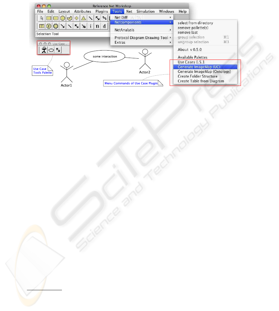
Fig. 1. The main window of Renew with the UseCase Plugin its palette, menu entries
and a use case example.
Figure 1 shows besides the main window of our development environment the addi-
tional elements provided to the GUI by the plugin: menu entries for the palette, for
generation of the image maps and for the creation of an application’s folder structure
and the palette for the basic drawing elements – here detached from the Window for
better recognition.
3 Examples: Coarse Design
In this section we present two examples for the modeling of the application matrix. One
is a workflow management system and the other one is a multi-agent multi-user game.
We use the previously described use case element syntax. However, the semantics and
pragmatics behind the diagrams are different form the usual application of use case di-
agrams and should not be confused with that. We call this model coarse design.
From the pragmatic point of view the largest difference between usual use case mod-
eling and the coarse design modeling lies in the stage or phase in which the model is
used. While use case diagrams are usually created during the requirements engineering
phase, coarse design is done after that and starts in the architectural design phase. How-
ever, as a system overview of all (or at least a closed partition of all) interactions and
roles it comes handy in all stages of development and should be maintained throughout
the whole process.
4
An addition to the plugin responsible for the documentation of the application (MulanDoc)
allows for the integration of the diagram as an image map into the web-based API documen-
tation.
38
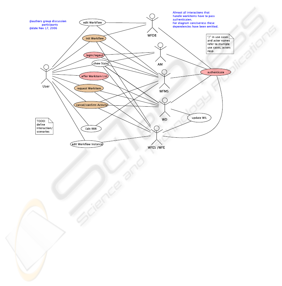
3.1 A Workflow Management System
Figure 2 shows an agent-based workflow management system that follows the defini-
tion of the Workflows Management Coalition’s (WfMC) reference architecture. The
management system is represented by the WFMS agent role.
Fig. 2. Coarse design of an agent-based workflow management system (WFMS).
Dependent agents (or sub-components) are workflow data base (WFDB) the account
manager (AM), the workitem dispatcher (WD), the workflow engines (WFE), the work-
flow enactment service (WFES) and a user of the workflow management system. An
agent owning the user role acts as a proxi/placeholder some real (human) user. Several
interactions have been defined; e.g.: login, logout, request workitem, cancel or confirm
activity and so on. Many of which (the ones involving the proxi user) are interactions
that can be interpreted also as interactions with the system. However, most require sev-
eral internal agents and some interactions are solely internally. Although the system has
not been built yet, the system’s structure is clearly conceivable from the coarse design.
Whether the system is build with exactly this structure is not of importance. The
main importance is that the development team has a means to develop a common vision
on the system from which further discussions can start. The Use Case Plugin allows to
extract a table from the diagram, which can be used to have yet another different view
on the system and also to compare with the existing designed system. Table 1 shows the
extracted table for the agent-based workflow management system.
39
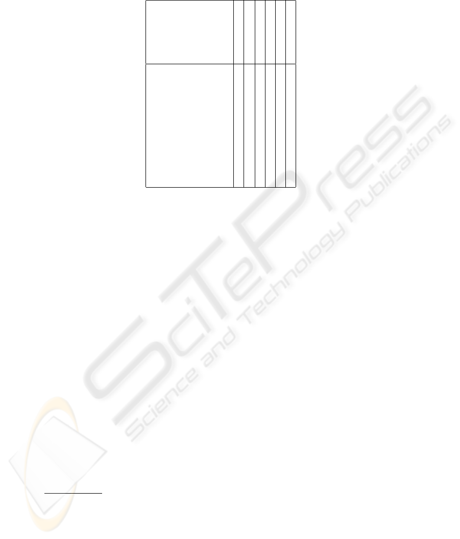
Table 1. Generated matrix table from diagram.
accountmanager
WIDispatcher
WFES
WFDEFDB
User
WFMS
offerWorkitemList × ×
edit Workflow Instance × ×
request Workitem × × ×
init Workflow × × × ×
show State × × × × ×
login × × ×
Edit RRR × ×
authenticate × × × × ×
cancelActivity × × × ×
dbEdit × × ×
updateWorkItemList × ×
3.2 Generating Code Bases From Coarse Design Diagrams
The coarse design models are used to generate the applications source code directory
as well as model skeletons, code skeletons for the roles, interactions and ontology as
well as all configuration and build files needed to compile the project. The diagram
is further used in other stages of the development process to add to the API docu-
mentation’s overview. In the html-based API Documentation,
5
which is automatically
generated from all design artifacts, the coarse design diagram is integrated and overlaid
with hyperlinks that lead from diagram elements directly to the documentations for the
represented artifacts.
4 Related Work
Use case diagrams are widely used to model requirements of (software) systems. This
is also done in agent-oriented methodologies. “Creating use-cases has proven to be a
very effective and sufficient method to discover requirements” [7, p. 6]. Examples for
such a use are ROADMAP and ADELFE. In opposition to this traditional use of the
use case syntax we redefine the semantics behind the diagram elements and transport
the technique from the requirements to the (coarse) design of the system.
Adapting the semantics of use case diagrams or diagram elements have been done
frequently within agent-oriented methodologies. It seems the temptation to use a human-
like icon for an agent is very high and the effect – the intuitive understanding of the
diagram element – is seldom missed.
5
Mulandoc generates a hyperlink document with and from all relevant design artifacts in a
MULAN-based multi-agent application including interaction diagrams, protocol nets, decision
components, knowledge base files and combines those with a generated application matrix as
well as the coarse design diagram. Thus it supplements the Java API documentation.
40

– In RAP/AOR use cases-like models are used alternatively to interaction frames
to model agent interactions. Agent can be modeled interchangeably as actors or
as systems while the cases depict interactions between agent and system (also an
agent).
– In MAS CommonKADS use cases are used to model interactions/cases of human
and artificial agents with a system (also an agent). The notation distinguishes be-
tween the human and the artificial (square head) agent. An artificial agent can be
depicted as (square headed) actor or as system depending on the focus.
– In PASSI use case diagrams are used for requirements engineering. Here the actors
are used in a more traditional sense as human agents / users but also sometimes as
external (outside of the system) resources.
– In INGENIAS use case diagram (with a slight variation in syntax) are used to define
the users interactions with the envisioned system. Here user roles, which define the
position of the human agents and are outside of the system, are related to use cases.
To sum up the usage of use case diagrams in agent-oriented requirements engineer-
ing. In general agents are seen as part of the system – depicted by the system border
in use case diagrams – and actors are often used to represent users of the system (hu-
man agents). However, depending on the grade of abstraction and the focus also agents
are sometimes depicted as actors. This reflects the ambiguous definition and the non-
fitness into traditional modeling approaches of the agent concept. In opposition, in our
approach we model the application matrix as identified agent roles, their interactions
and the connections of both in the stage of analysis or coarse design.
However, the application matrix can be found in central models of almost all agent-
oriented methodologies. In Gaia this information is defined in the preliminary role and
interaction model. In Prometheus[9] the systems model contains the matrix of interac-
tions and agents. However, it is hidden behind several other aspects that are defined in
this central diagram (perceptions, data). Instead as an alternative the agent acquaintance
models show the social network of the agents withholding the information about inter-
actions.
In (object-oriented) software engineering use case modeling is a common and well-
established technique [6] (especially in analysis of systems). Also system elements (e.g.
components) are modeled frequently as actors (e.g. system use cases [4]) similar to the
above mentioned approaches. In contrast, in our presented approach we do not define
any use cases. Instead we focus on the use case diagram for a coarse and concise design
of the system.
41
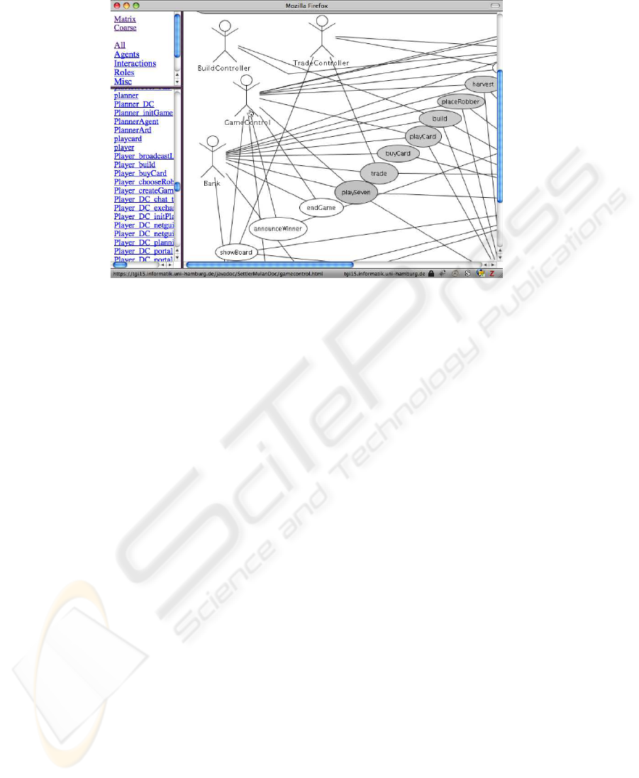
Fig. 3. Screen-shot of a browser window showing a coarse design image with hyperlink
overlay.
5 Conclusions
In this paper we present a simple technique for the modeling of the application matrix
in multi-agent system, which constist in roles and interactions. The resulting models
can be facilitated for a variaty of causes throughout the development process from the
early stages over generation of code bases to the documantation.
In early stages (coarse design) the light-weight technique presented here allows to
model on-the-fly – while the ongoing developers group discussion – in a coarse manner
the basic system decomposition and coarse overview in an intuitive way. It allows to
be changed rapidly during development. From the artifact, which also reflects the orga-
nization of the development team, a system code project folder can be generated that
allows for immediate and concurrent beginning of detailed design / coding. Also other
representations can be derived from the model; i.e. the matrix as a spreadsheet or table.
Additionally, the model is automatically integrated in the hypertext-based API docu-
mentation of the multi-agent system, including navigation with hyperlinks included in
the diagram image.
References
1. Lawrence Cabac. Multi-agent system: A guiding metaphor for the organization of software
development projects. In Paolo Petta, editor, Proceedings of the Fifth German Conference on
Multiagent System Technologies, volume 4687 of Lecture Notes in Computer Science, pages
1–12, Leipzig, Germany, 2007. Springer-Verlag.
2. Lawrence Cabac, Till D
¨
orges, Michael Duvigneau, Daniel Moldt, Christine Reese, and
Matthias Wester-Ebbinghaus. Agent models for concurrent software systems. In Ralph
42

Bergmann and Gabriela Lindemann, editors, Proceedings of the Sixth German Conference
on Multiagent System Technologies, MATES’08, volume 5244 of Lecture Notes in Artificial
Intelligence, pages 37–48. Springer-Verlag, 2008.
3. Lawrence Cabac, Till D
¨
orges, Michael Duvigneau, Christine Reese, and Matthias Wester-
Ebbinghaus. Application development with Mulan. In Daniel Moldt, Fabrice Kordon, Kees
van Hee, Jos
´
e-Manuel Colom, and R
´
emi Bastide, editors, Proceedings of the International
Workshop on Petri Nets and Software Engineering (PNSE’07), pages 145–159, Siedlce,
Poland, June 2007. Akademia Podlaska.
4. Alistair Cockburn. Writing Effective Use Cases. Addison-Wesley Longman, 2000.
5. J. Ferber. Multi-Agents Systems - An Introduction to Distributed Artificial Intelligence.
Addison-Wesley, 1999.
6. Ivar Jacobson, Magnus Christerson, Patrik Jonsson, and Gunnar
¨
Overgaard. Object-oriented
Software Engineering; A Use Case Driven Approach. Addison-Wesley, Wokingham, Eng-
land, 1992.
7. Thomas Juan, Adrian R. Pearce, and Leon Sterling. ROADMAP: extending the gaia method-
ology for complex open systems. In AAMAS, pages 3–10. ACM, 2002.
8. Michael K
¨
ohler, Daniel Moldt, Heiko R
¨
olke, and R
¨
udiger Valk. Linking micro and macro
description of scalable social systems using reference nets. In Klaus Fischer, Michael Flo-
rian, and Thomas Malsch, editors, Socionics: Sociability of Complex Social Systems, volume
3413 of Lecture Notes in Artificial Intelligence, pages 51–67. Springer-Verlag, 2005.
9. Lin Padgham and Michael Winikoff. Prometheus: a methodology for developing intelligent
agents. In AAMAS, pages 37–38. ACM, 2002.
10. Franco Zambonelli, Nicholas R. Jennings, and Michael Wooldridge. Developing multiagent
systems: The Gaia methodology. ACM Transactions on Software Engineering and Method-
ology, 12(3):317–370, July 2003.
43
