PROMOTION IN RESCUE ROBOT
According to the Experience Gained by Participating in Bam Earthquake
Rescue Operation
Pooya Heiraty, Aboozar Aghajani, Hojatollah Shirzadi Laskoukelayeh, Majid Zeraat Pisheh Fard
and Sayyed Mohammad Hosseini Monsef
Department of R&D, Sprooz International Co., Ltd., Flat No. 2, No.9, Eftekhar St.
Valiasr St., Next to Motahhari Junction, Tehran, Iran
Keywords: Four-Wheeled Robot, Locomotion, Control, Communication, Sensor, Navigation, Victim, Differential
Drive, Map Generating, Bam Earthquake, Rescue Robot, Operator.
Abstract: Nowadays rescue robots are used in some rescue operations. Increasing the speed and accuracy of victim
detection with sensors and equipment which are installed on the robot and yet increasing human safety
factor of rescuers are among the advantages of using rescue robots.
By the experience of rescue operation in Bam earthquake and participating in some robocup competitions, a
new four-wheeled robot has been designed which has highly operational capability. In initial part of this
article, robot locomotion and controlling in different situations and the method of connection operator with
robot are surveyed; then, sensors which are used in for navigation and victim detection are explained. At the
end, the method of generating the map of robot’s movement route, which is very important for identifying
the trapped victim's location in a rapid rescue operation, was studied.
1 INTRODUCTION
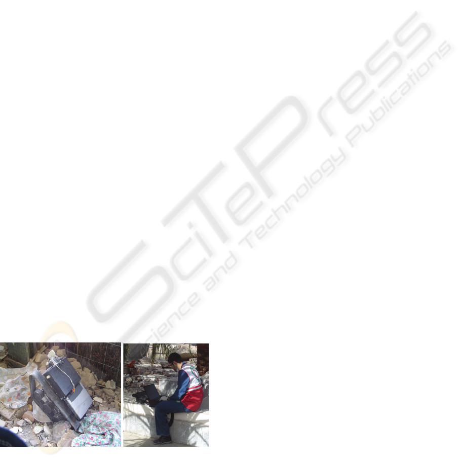
In December 2003, a severe earthquake destroyed
one southern Persian city called Bam. This
earthquake was the most devastating earthquake in
the Middle East. Writers of this article who have
been designing and building several robots, joined
the rescue teams with their rescue robots and
searching devices for detecting victims.
Figure 1: Robot navigation in Bam earthquake collapses.
By the experience of Bam earthquake, another
rescue robot was designed and built whose
characters would be describe in this article. This
robot has high movement capability which could
traverse the obstacles easily. The electronical and
software parts of the robot have the ability of
distance navigation, victim detection, and generating
the map of victim places.
Individual Height adjustment of each wheels,
carrying baby robot with ability of separating from
the main robot and going through the small hole
which the main robot could not goes, rapid ability
for changing from four-wheeled to the track
situation and mapping ability in both systems are
among interesting idea which are used on this robot.
2 ROBOT LOCOMOTION AND
OTHER MECHANISMS
The designed rescue robot is based on the
four-wheeled robot mechanism. The design and
production of it is so that the robot has a high
capability of movement so that it can traverse the
obstacles and unevenness easily. This robot is made
using modern technology
.
195
Heiraty P., Aghajani A., Shirzadi Laskoukelayeh H., Zeraat Pisheh Fard M. and Mohammad Hosseini Monsef S. (2009).
PROMOTION IN RESCUE ROBOT - According to the Experience Gained by Participating in Bam Earthquake Rescue Operation.
In Proceedings of the 6th International Conference on Informatics in Control, Automation and Robotics - Robotics and Automation, pages 195-201
DOI: 10.5220/0002203201950201
Copyright
c
SciTePress
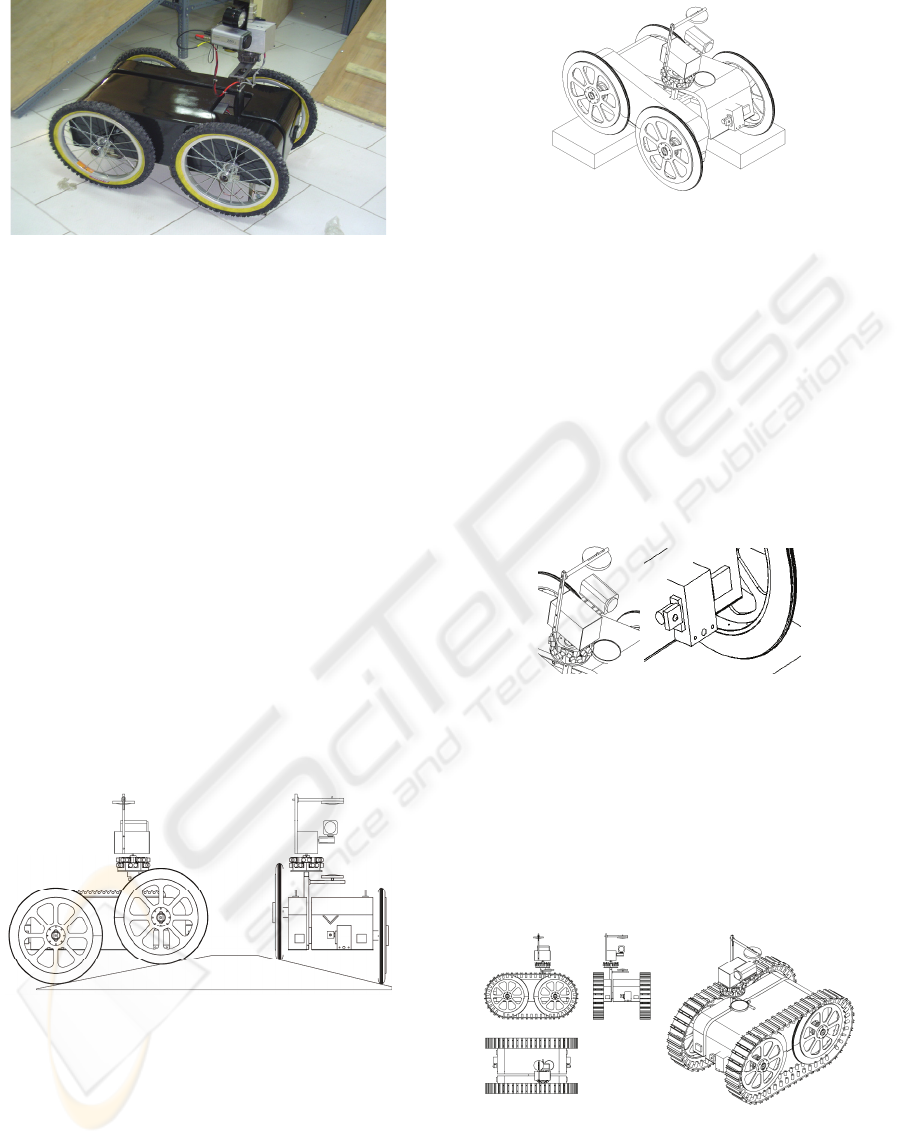
Figure 2: The robot.
The designed robot has four moving wheels and
its dimensions are 87*50*80 cm. The weight of
robot is about 32 kilograms. Four DC 12 V engines
are used for the moving system of the robot each of
them acts independently. The velocity of the robot is
about 1 m/s and the rotation speed is 30 degrees per
second.
The central computer which has the duty of
processing, receiving and transmitting the data is an
industrial PC (PC-104). Four packs of batteries of
Ni-cadmium type are used to supply robot energy.
This robot uses the height adjustment system and
the height of each wheel can be adjusted separately.
By using this system the robot can easily climb the
obstacles. Also in those cases where the patrol area
is crowded, and there is a possibility for the bottom
of the robot to collide with the obstacles, the height
of robot could be increased to remove this problem.
The changing range of the height in this robot is
about 10 centimeters and the height is adjustable at
the speed of two centimeters per second.
Figure 3: The height adjustment system.
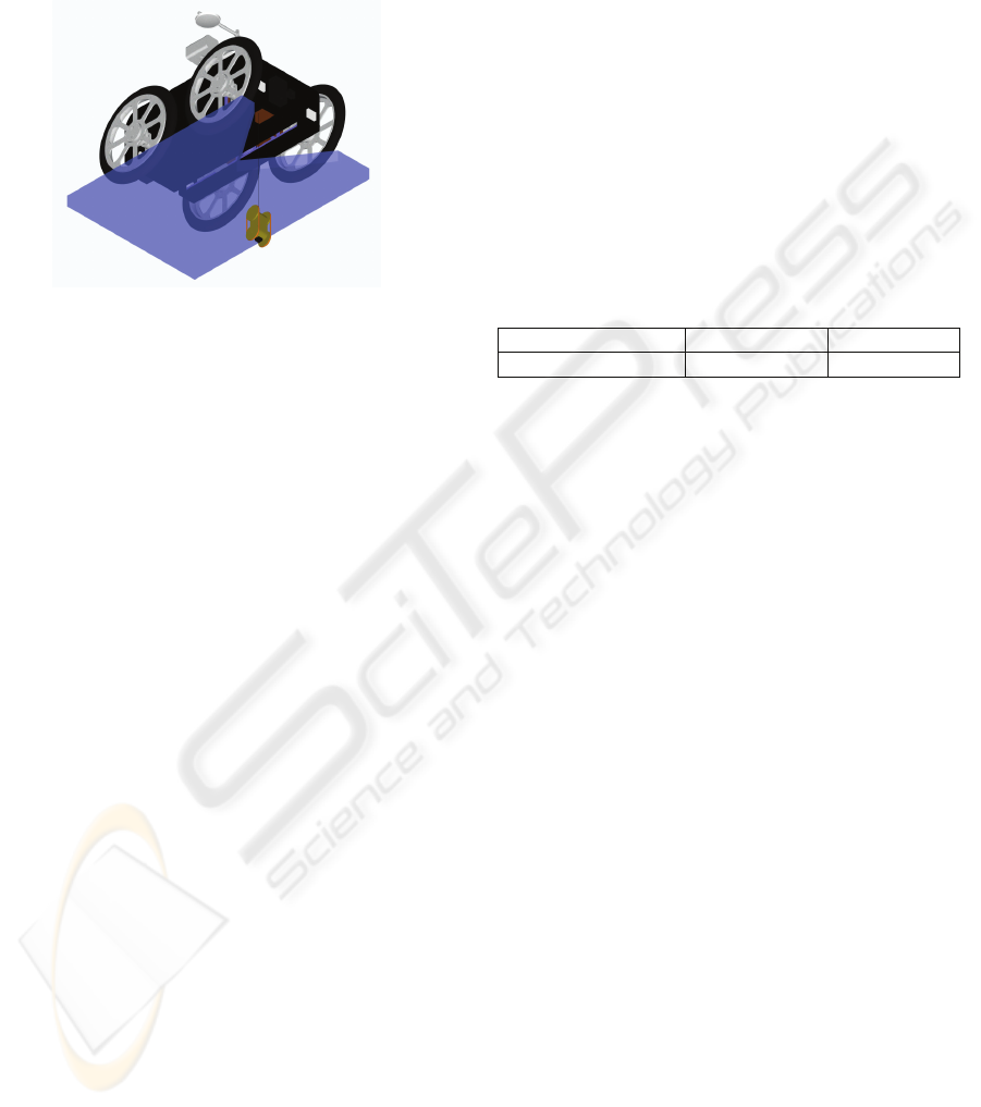
In order to increase the moving ability, an innovative
suspension system is used in this robot. This
suspension system is devised in the form of a joint at
the middle of the robot. This joint is capable of
being locked at any angle and can help robot to
traverse the obstacles and unevenness. The freedom
degree of the joint is between -20 to +20. The time
needed for the joint to be locked is about three
seconds.
Figure 4: Joint suspension system of the robot.
To control the robot, three moving cameras are
used. One of which is at the front the other at the
back and the last one is located on the top of robot.
The camera which is located on the robot is
equipped with two Omni-directional mirrors above
and under the camera. These mirrors give the robot
the opportunity to have a visual angle of 360 degrees
vertically.
Under the pedestal of the camera, there are 12
Sonar sensors which have the duty to help the robot
in measuring the distance
and also to obtain the map
of environment.
Figure 5: Pan-tilts and omni-directional mirrors.
The speed of the cameras at the back and front
which are moved by RC Servos is about 50 degrees
per second and the speed of the camera on the above
is about 10 degrees per second.
For increasing the moving ability of the robot in
special environments, and the ability of changing the
moving system, four-wheeled tracked are used. It
could be very rapid to change this situation.
Figure 6: Track system.
In order to increase the searching ability of robot,
a baby robot is used which is located inside the robot
and it will exit whenever it is necessary. This baby
robot is linked to the main robot through a cable.
ICINCO 2009 - 6th International Conference on Informatics in Control, Automation and Robotics
196
The moving system of this robot is of the
four-wheeled type, its dimensions are 15*10*8 cm
and it weighs 1 KG. Two DC (12 V) engines are
used in its moving system. The moving speed of the
robot is about 0.2 m/s.
Figure 7: Baby robot.
3 CONTROL METHOD AND
HUMAN-ROBOT INTERFACE
Controlling the robot is a partial autonomy. The
major part of the controlling effort is performed by
the operator and some movement decisions are made
by the robot itself with the prior permit of the
operator (which will be activated in the robot
guiding software). Some of these decisions are: to
automatic prevent collisions with the surrounding
environment and to automatic return the robot to the
starting point. But the software is designed so that
the human decisions are considered prior to the
robot decisions. For instance, in a narrow place the
operator may deem it reasonable for the robot to
collide with the walls so that it can pass the narrow
entrance; therefore the orders of the operator are
considered prior to the automatic decisions of the
robot.
Regarding the mechanical specifications and the
moving situation of the robot, three situations are
defined for its movement: slow speed, medium
speed and fast speed. The operator determines which
of the above mentioned speeds shall be selected. But
when the robot moves on a slope, the robot's
movement will be set automatically according to the
angle of the slope (which will be measured by
ADXL330 accelerometer) and the software setting
in which speed of the robot, while moving on the
slope, is determined.
Moreover the PID controller is used to correct
the mechanical errors and to adjust the exact speed
of the robot in different situations.
4 COMMUNICATION
Regarding the fact that the robot is a PC base,
W-Lan was used to establish connection between the
robot and the computer (operator). Moreover, since
in some regions it is impossible to establish wireless
connections because of the high rate of noise, the
capability of making connections through wire was
added to the above system so that establishing the
connection is practical even for long distances
(several kilometres). A wire gathering system is
devised inside the robot which could spread the long
wire simultaneous with the robot's movement when
connections shall be established through wire. In this
way the wire will not hinder the robot while moving
and it does not interfere with the robot's movement.
Table 1: W-Lan Specification.
Frequency Channel/Band Power (mW)
5.0 GHz - 802.11a
4 100
Through displacing a few simple jumpers which
are devised on the robot and also through activation
of the multiple choices exist in the provided
software, we can easily determine the method for
establishing connection with the robot.
To transmit the video pictures and voice, the 3W
video transmitter with 2GHz frequency are used.
5 SENSOR FOR NAVIGATION
AND LOCALIZATION
The baseline of navigation in a robot is to use
graphical and video pictures sent by various cameras
and Sonar system installed on the robot. Processing
data, sent by cameras, is performed by the operator
and the data sent by sonar system will be processed
by a central microcontroller.
In addition to sonar system, several photo
sensors are also installed on the robot's critical
movement points which prevent robot colliding with
the surrounding environment. According to the robot
maximum speed, the identifying distance of obstacle
by sensor is adjustable in a way that the robot will
not collide the obstacles.
In order to locate the robot, a combination of
data sent by various sensors are used which reduce
the errors (that are inevitable). Increasing the rate of
certainty in identification, grouping and also
eliminating of the ambiguities & conflicts are among
the benefits of this work. To perform the data
combining system, it requires selecting and using the
PROMOTION IN RESCUE ROBOT - According to the Experience Gained by Participating in Bam Earthquake Rescue
Operation
197

group of techniques harmoniously to achieve the
best answer.
In order to apply the intelligent combination of
data from the viewpoint of data processing, the high
level method is used.
These sensors include:
Four encoders which are mounted onto the
motor shafts.
Digital compass plus µ-metal to eliminate the
noise of engines which could completely
disable the digital compass sensor.
the accelerometer sensor which obtains the
robot's vertical angle in two vertical directions
robot (using ADXL330 IC which most
importantly is used to obtain the vertical angle
(zx, zy) of the robot and to measure the height
of the distance traversed by the robot).
To use the data provided by these sensors for
illustrating the map, the following definitions shall
be considered.
The break points: whenever the command for the
robot's movement sent by operator through PC is
interrupted or the Stop command is transmitted to
the robot, that place will be considered as break
point.
Figure 8: Break points for drawing map of robot's
movement.
Note 1: the angle and the measure of the
traversed distance from the previous break point and
also the vertical distance of the robot from the
horizontal line of the starting point will be desirable
at the break point.
Note2: B3 is also defined as a break point here
because the robot's movement in the straight
direction is interrupted although it continued to
move without changing its direction.
Note3: having the data about the robot's location
(angle and the distance) at the break points, in an
ideal condition we could illustrate the route map of
robot in an accurate and simple way. This is the
advantages of the break point definition.
The movement route: the robot's route of movement
is obtained through connecting the vectors of break
points.
Note4: the specifications stated in note 1, will be
stored in the side memory of the robot in a special
arrange. Whenever the investigating operation is
finished, returning to the starting point could be
automatically delegated to the robot by using the
reversed combination of the stored data and
real time data provided by the sensors
simultaneously. (Obviously facing changes in the
environment is unavoidable thus just in the ideal
situation saved break points are used for returning to
the start point and in real situation the real time data
of sensors which could rectify the previous errors
are used to obtain the new break points.)
Note5: Advantages of storing the data about
break points in the side memory:
The automatic returning of robot even in cases
when the operator and the robot are
disconnected.
Access to the data in different steps of
movement in order to perform the combining
operation of the data provided by sensors
(sensor fusion) to obtain a relatively accurate
mapping.
Access to the complete information of the route
stored inside the memory so that in case the
robot and PC are disconnected, the
information could be transferred to PC (after
returning of the robot).
6 SENSORS FOR VICTIM
IDENTIFICATION
The most important method to identify the victim, is
using pictures transmitted by the cameras which are
installed on the robot (three cameras are installed on
the robot but by using an analog switcher, the
operator selects one of the pictures provided by one
of these cameras to be transmitted.
And besides we can use:
CO2 gas sensors for detecting the victim's
breathing.
Installation of highly sensitive stereo
microphones on the robot helps the operator to
find the victim.
LM75 IC for measuring the temperature of the
environment.
The non-contact thermometer sensor model
IL301, with D:S (30:1) for measuring the
body temperature of the victim from a far
distance.
Also a motion detector is installed on the robot
which is sensitive to any trivial movement in
the environment.
ICINCO 2009 - 6th International Conference on Informatics in Control, Automation and Robotics
198
7 ROBOT MECHANIC AND
LOCALIZATION
Firstly, we describe the mathematical equations of
localization differential mechanism and then by
using those equations, we could generate
four-wheeled robot and tracked robot equations with
acceptable accuracy.
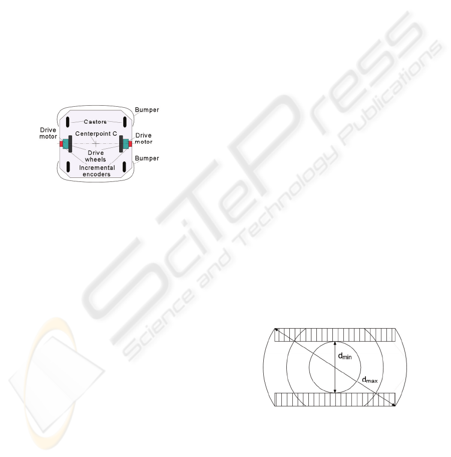
7.1 Differential Drive
Figure 9 shows a typical differential drive mobile
robot. In this design incremental encoders are
mounted onto the two drive motors to count the
wheel revolutions. The robot can perform dead
reckoning by using simple geometric equations to
compute the momentary position of the vehicle
relative to a known starting position.
Figure 9: A typical differential drive mobile robot
(top view).
20 Part I Sensors for Mobile Positioning For
completeness, we rewrite the well-known equations
for odometry below. Suppose that at sampling
interval I the left and right wheel encoders show a
pulse increment of N
L and NR, respectively. Suppose
further that:
C
m = π Dn / n Ce (1)
where:
C
m = conversion factor that translates encoder pulses
into linear wheel displacement
D
n = nominal wheel diameter (in mm)
Ce = encoder resolution (in pulses per revolution)
n = gear ratio of the reduction gear between the
motor (where the encoder is attached) and the drive
wheel.
We can compute the incremental travel distance
for the left and right wheel, ΔU
L,i and ΔUR,i
according to:
ΔU
L/R,i = Cm NL/R,i (2)
And the incremental linear displacement of the
robot's center point C, denoted ΔU
i, according to:
ΔU
i = (ΔUR + ΔUL)/2 (3)
Next, the robot's incremental change of
orientation was computed:
Δθ
i = (ΔUR - ΔUL)/b (4)
Where b is the wheelbase of the vehicle and
ideally measured as the distance between the two
contact points between the wheels and the floor.
The robot's new relative orientation θ
i can be
computed from:
θ
i = Δθi-1 + Δθi (5)
And the relative position of the center point
is:
x
i = xi-1 + ΔUi cos θi (6)
yi = yi-1 + ΔUi sin θi (7)
where:
x
i, yi = relative position of the robot's counterpoint c
at instant i.
7.2 Tracked Vehicles
Yet another drive configuration for mobile robots
uses tracks instead of wheels. This very special
implementation of a differential drive is known as
skid steering and is routinely implemented in track
form on bulldozers and army vehicles. Such
skid-steer configurations intentionally rely on track
or wheel slippage for normal operation (Figure 10),
and as a consequence provide rather poor
dead-reckoning information. For this reason, skid
steering is generally employed only in tele-operated
as opposed to autonomous robotic applications,
where the ability to surmount significant floor
discontinuities is more desirable than accurate
odometry information. An example is seen in the
track drives popular with remote-controlled robots
intended for explosive ordnance disposal.
Figure 10: The effective point of contact for a skid-steer
vehicle is roughly constrained on either side by a
rectangular zone of ambiguity corresponding to the track
footprint. As is implied by the concentric circles,
considerable slippage must occur in order for the vehicle
to turn.
PROMOTION IN RESCUE ROBOT - According to the Experience Gained by Participating in Bam Earthquake Rescue
Operation
199
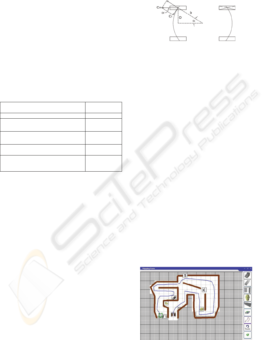
7.3 Four-wheeled Vehicles
Obtaining the robot route map is one of the issues
about which designer really concern. For this, there
are simple mathematic equations. The robot route
map equations parameters are described below.
These equations are valid while wheels revolutions
are equal, it means that the robot should go forward,
backward or rotate at its place and could not use
these equations in complicate movement. In rotation,
robot changing angle is calculated and it has no
movement.
Table 2: Parameters of movement route for four-wheeled
robots.
Dimensional distance traveled by wheel
for each encoder pulses
Ct
Effective width of robot divided by two O
Incremental travel distance for the left and
right wheel in the straight movement
ΔUR1 = ΔUL1
Incremental travel distance for the left and
right wheel in u turn movement
ΔUR2 = ΔUL2
Number of pulses received by left and
right encoder
NR,i = NL,i
Wheelbase of the vehicle, measured as the
distance between the two contact points
(wheels & floor)
b
The mathematic equations of robot route
movement are described below:
Sin α = O / b
(8)
C
m = лDn / nCe
(9)
ΔU
L1 = Cm NL,i
(10)
ΔU
R1 = Cm NR,i
(11)
C
t = Cm × Sin α
(12)
ΔU
L2 = Ct NL,i
(13)
ΔU
R2 = Ct NR,i
(14)
ΔU
i = (ΔUR1 + ΔUL1 ) / 2
(15)
ΔӨ
i = ΔUR2 / b
(16)
Ө
i = Өi-1 + ΔӨi
(17)
X
i = Xi-1 + ΔUi cos Өi
(18)
Y
i = Yi-1 + ΔUi sin Өi
(19)
If compass sensor or gyroscope use more
than encoders, ΔӨ
i parameter is directly obtained
from sensors and other movement route equations
shall use without change.
Figure 11: A typical four-wheeled drive mobile robot
(top view).
8 MAP GENERATION
The map generation process, for illustrating the
route of robot's movement is studied on this part.
The recorded data, observed by cameras and also the
piece of information were received by various
sensors, illustrated on the map of robot movement
(in form of a general report for the robot
performance). This part consists of two parts called
automatic mapping and manual mapping which the
automatic mapping is chosen as the default. The
work procedure is as follows:
Data about shaft encoders exist on the robot, and
the data received through the digital compass sensor
are transmitted continuously from robot. The
computer firstly combines the received data and
applies a series of error correcting algorithms to
reduce the errors of shaft encoders (sensor fusion)
and then the coordinates of the robot in each second
will be obtained. By using these coordinates, two
dimensional routes of robot's movement will be
illustrated. Meanwhile, the data provided by gas and
voice sensors, transmitted by the robot, will be saved
in the computer and they will be illustrated on the
map at the place which they were received. In
addition, some tools are designed for the operator by
which the operator can record its observations and
insert information in the map.
Figure 12: The scheme of the software used to illustrate
the route map.
ICINCO 2009 - 6th International Conference on Informatics in Control, Automation and Robotics
200
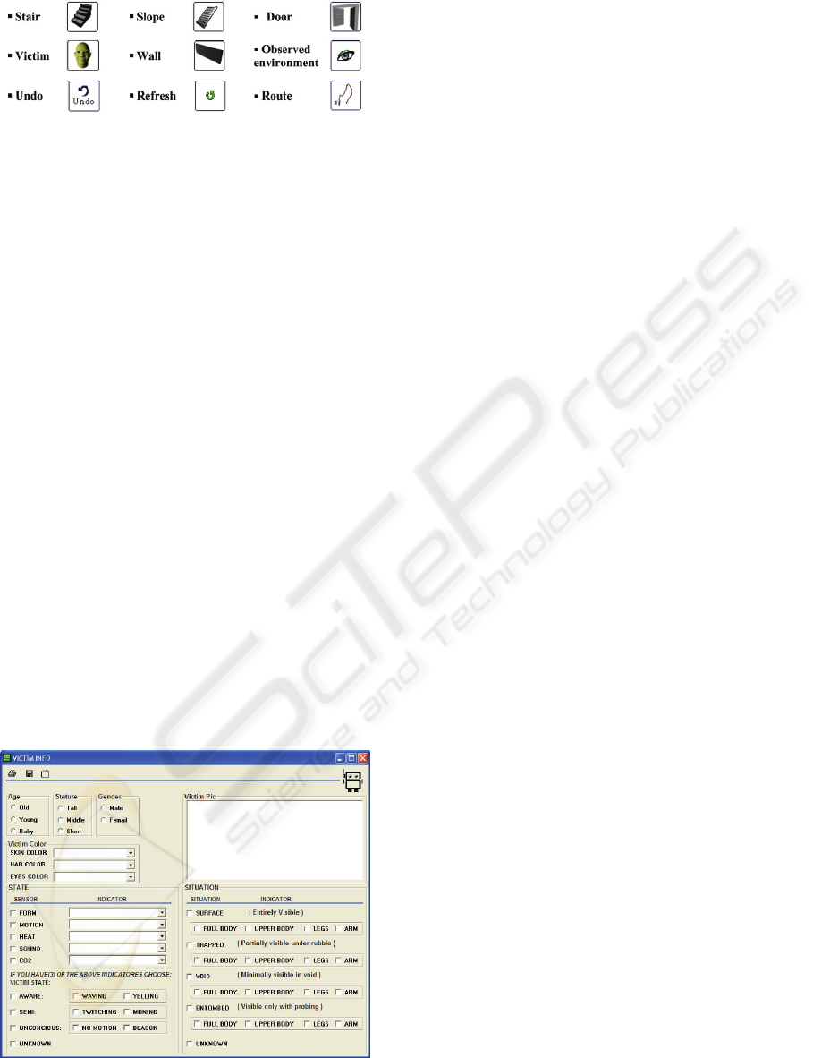
Figure 13: Symbols which are used in map generating.
Whenever the operator realizes that at the place
where the robot locates or at its surroundings, there
is a stair, wall, door, slope, or a victim, it can locate
a symbol of what it observes on the route map.
By using observed environment button and while
navigating the robot, the operator will mark the
places visited by the robot to prevent the repetitive
visiting and then, saves time. For returning to the
previous situation the operator just need to press
undo button.
While working, whenever the robot and the
computer are disconnected or whenever major errors
in the coordinates data or the data provided by
sensors are observed which may caused as a result of
robot damage, the operator can select the manual
mapping choice to illustrate the route. In this way,
he can enjoy the benefits of software in controlling
the robot and will face fewer errors.
In case that operator uses each of the above
objects in a wrong place, the software has the ability
to delete the object by a right click or to replace it by
a left click. The places in white colour show that
they are observed by the operator.
While observing an injured person, and placing
its symbol on the route map, another form will
appear for the operator in which the operator should
enter the related data to be recorded and also to be
used for the next reportages.
Figure 14: Form for recording the victim data.
9 CONCLUSIONS
Height adjustment and suspension systems enrich
the robot to go through the entirely destructed
buildings; however, it is not possible for it to cross
some obstacles such as steps. Robot mapping system
acts perfectly inside the buildings, but in the open
areas or the rubble it needs to improve. In the
improvement plan, these limitations must be
removed. In its final version, laser scanner and radio
positioning will be installed. The received
information plus the other sensors data result in a
better mapping achievement. It order to accelerate
its movement on the steps and through the obstacles,
some changes will be applied on the wheels and the
motion system.
ACKNOWLEDGEMENTS
Prof. Caro Lucas.
Dr. Soleiman Farshid Fam.
Dr. Sayyed Hassan Mir Hosseini.
REFERENCES
Heiraty, P., Aghajani, A., Chitsazan, M., 2008. The
applied knowledge of designing and building robot.
Azarakhsh publishing company. Tehran, 1
st
edition.
Borenstein, J., Everett, H. H., Feng, L., 1996. Where am I?
Sensors and Methods for Mobile Robot Positioning.
The University of Michigan. Michigan, 1
st
edition.
Ko, Albert., Y. K. Lau, Henry., 2009. Robot Assisted
Emergency Search and Rescue System With a Wireless
Sensor Network. International Journal of Advanced
Science and Technology field. Vol. 3, February.
Sandin, P. E., 2003. Robot Mechanisms and Mechanical
Devices Illustrated. McGraw-Hill Company. New
York, 1
st
edition.
Jacoff, A., Messina, E., Evans, J., 2000. A Standard Test
Course for Urban Search and Rescue Robots,
Intelligent Systems Division. National Institute of
Standards and Technology.
Jacoff, A., Messina, E., Evans, J., 2000. Experiences in
Deploying Test Arenas for Autonomous Mobile
Robots, Intelligent Systems Division. National Institute
of Standards and Technology.
RoboCup and AAAI rescue robot competition rules, 2008.
PROMOTION IN RESCUE ROBOT - According to the Experience Gained by Participating in Bam Earthquake Rescue
Operation
201
