
COOPERATIVE UAVS MAPPING COMPLEX ENVIRONMENT
USING 2D SPLINEGON
Samuel B. Lazarus, Antonios Tsourdos, Brian A. White, Rafał
˙
Zbikowski and Peter Silson
Department of Informatics & Sensors, Cranfield University
Defence Academy of the United Kingdom, Shrivenham, U.K.
Keywords:
Multiple sensor fusion, Circle Packing, Path planning, Integrated GPS/INS navigation, Obstacle and collision
avoidance, Splinegon, Boundary estimation and Data association.
Abstract:
This paper presents a novel approach which enables multiple UAVs to efficiently explore an unknown envi-
ronment and incrementally build the map of the area and its complex shaped obstacles, represented here as
concave and convex in shape. The task is achieved by a improved performance of sensor based searching,
navigation and mapping of these complex shaped obstacles in an unknown environment. The improved per-
formance is quantified by explicit bounds of navigating the UAVs using an extended Kalman filter and to build
the map of the complex shaped obstacles using the 2-D Splinegon. The circle packing search algorithm is used
for the completeness of coverage in searching the unknown obstacles regions and the UAVs trajectories are
generated by the Dubins path planning algorithm. This novel proposed algorithm results in a robust approach
to search and map the obstacles using multiple UAVs that is also computational attractive.
1 INTRODUCTION
This paper focusses on swarm of UAVs deployed for
a mission of searching an unknown region to detect
obstacles and to extract their shape. The circle pack-
ing search algorithm (Kershner, 1939), (Guo and Qu,
2005) is implemented where the search is carried out
by a sequence of “looks” each of which covers a circle
corresponding to the footprint of the sensor on board.
This circle pacing algorithm covers the plane by pack-
ing each circles into the unknown environment. The
centers of each of this packed circles represent the
way points to be used on path planning of the UAVs.
A mission planning algorithm is described which en-
ables the UAVs to switch between the searching mode
and the mapping of the detected obstacle. Since the
swarm of UAVs fly around an unknown environment,
a sense and avoid system is developed so the UAVs
autonomously replan their paths when they approach
an obstacle or predict intersection of air traffic. Thus
the system presented here provides a safe surveillance
of unknown areas by swarm of UAVs. Furthermore
the proposed mission planning not only enables the
swarm of UAVs to switch from searching mode into
mapping mode, but also ensures the allocation of the
required number of UAVs to map that obstacle with
in searched region.
In the fulfillment part of the mapping task, the
measurements from laser sensor that are mounted on
the UAVs is the only source to construct the map of
the detected obstacle. This strongly suggests that the
most efficient way in modelling approach should be to
define these measurement points as vertices that can
form a polygon with line segments. This raises an is-
sue as to how to represent the curved nature of these
obstacles. One such promising approachis introduced
in this paper that uses a generalization of polygons
that produces a set of vertices that are connected by
line segments of constant curvature. This is a sub-
set of a class of objects named as splinegons (Dobkin
et al., 1988), (Dobkin and Souvaine, 1990).
In the mapping process the fused EKF estimated
positions are used with the limited number of mea-
surements (i.e. required number of the the interpola-
tion points) from the laser sensors to build the map.
As the vehicles fly around the obstacle, sensors such
as laser sensors are used to measure the distance to
the obstacles. Out of all these measurements, only a
carefully selected number of measurements are cho-
sen which represent the required vertices to construct
a simple polygon. The data association algorithm is
implemented to select a limited number of vertices
and to uniformly distribute these vertices around the
obstacle in a computationally efficient way. This se-
413
Tsourdos A., White B., Lazarus S., Silson P. and
˙
Zbikowski R. (2009).
COOPERATIVE UAVS MAPPING COMPLEX ENVIRONMENT USING 2D SPLINEGON.
In Proceedings of the 6th International Conference on Informatics in Control, Automation and Robotics - Robotics and Automation, pages 413-416
DOI: 10.5220/0002204804130416
Copyright
c
SciTePress

lection of maximum number of vertices that can form
a polygon is limited from sixteen to twenty vertices.
This selection of vertices is accomplished by calcu-
lating the length and the curvatures between each of
the vertices and to eliminate the vertex that has a min-
imum length and curvature. The selection process is
based on the size and the curved nature of the obsta-
cle. Thus, the constructed polygon is generalised to
produce a set of vertices that are connected by line
segments of constant curvature called splinegon. This
splinegon is a set of vertices that have constant cur-
vature line segments defined with C
2
contact at the
vertex points.
1. The prediction of next way points for the search
algorithm and prediction of a new way points
when obstacle/collision avoidance algorithm is
activated.
2. Switching between the search mode into the map-
ping the unknown obstacle and predict the way
points and its orientation to get the measurements.
3. The prediction of the required number of vehicle
to accomplish the mapping task (How many vehi-
cle is needed to complete the mission?)
4. If more then one UAV is used for the mapping
task,
(a) Find a shortest way points for the other UAVs
to reach the mapping region.
(b) Whether the UAVs needs to exchange the infor-
mation with one to another, and
(c) Identify the state of the obstacle whether it is
single or multiple, depending upon the intersec-
tion detection between the local updates. Even-
tually, the global update is performed between
the intersection detected UAVs.
5. The prediction of required number of measure-
ment for the mapping from each of the detected
obstacles.
This newly proposed algorithm gives a solution that
has a highly richness in building the curved nature
of the unknown obstacle in an unknown environment.
This proposed approach is a computationally attrac-
tive one resulting in information driven mission plan-
ning and the mapping of unknown environments with
limited measurements.
The development of this algorithm is shown in the
functional block diagram in figure 1.
EKF based
Localisation
INS
Measurements
GPS
Measurements
Vertex Selection and
Data Association
TOF Laser sensor
Measurements
Constructing the Polygon
with Line Segments
Mapping the obstacle
using 2-D Splinegon
Yes
Predicting the next way
points for mapping
Unknown Environment
with Unknown Obstacles
Circle Packing
Algorithm
Prediction of
way points
Initial position
of the vehicles
Trajectory Generation
using Dubins Algorithm
Obstacle\Collision
Avoidance Algorithm
Search for obstacles
Decision Making
Algorithm
Switch Between
Searching & Mapping
Required number of the
vehicles for Mapping
Prediction of next
way points for search
Choosing the shortest way
points for mapping
Required number of the
measurements for Mapping
Prediction of new
way points
No
Sensor Fusion
Figure 1: The functional block diagram.
2 PATH PLANNING AND CIRCLE
PACKING ALGORITHM
The path planning algorithm generates a flyable and
safe path to the UAVs to fly from one location to an-
other. The locations are predefined by the way-points.
The starting location is called base and the final loca-
tion to be reached is called target. The Dubins set of
paths is used to connect the base and target by a se-
quence of successive way-points. The base and the
target are characterized by the poses, in a set of posi-
tion coordinates (x,y) and orientation θ of the UAVs.
Considered that an initial pose P
s
(x
s
,y
s
,θ
s
) at the base
and a final pose at the target P
f
(x
f
,y
f
,θ
f
) are given,
the path r(t) connecting the two poses can be a sin-
gle or a composite curve. A path represented by a
curve in 2D is completely determined by its curvature
(Kreyszig, 1991) and the maximum curvature bound
of the UAV by κ
max
and other constraints by
∏
; then
the path planning can be mathematically represented
as:
P
s
(x
s
,y
s
,θ
s
)
r(t)
−→P
f
(x
f
,y
f
,θ
f
), κ(t) < κ
max
,
∏
(1)
Extending the equation (1) for a group of UAVs, this
changes into:
P
si
(x
si
,y
si
,θ
si
)
r
i
(t)
−→ P
fi
(x
fi
,y
fi
,θ
fi
)
κ
i
(t) < κ
i,max
and
∏
(2)
where κ
i
(t) is the curvature, κ
i,max
is the maximum
curvature bound of i
th
path, and i = 1...N, N is the
number of UAVs. This path planning algorithm is in-
tegrated with an obstacle and Collision avoidance sys-
tem to generated the trajectories for each UAVs and
to protect the flying UAVs from any collision with the
surrounded obstacles or with the on coming UAVs.
This algorithm is applied online while the UAVs are
in motion.
The circle packing algorithm (Washburn, 1981) is
to attempt to cover the given plane by packing the
ICINCO 2009 - 6th International Conference on Informatics in Control, Automation and Robotics
414
circles of radius R. In other words finding a mini-
mum number of circles with the radius of R to com-
pletely cover in the given area of search. This is ac-
complished by fixing the coverage range or the sensor
range are represented as a circle. The key problem
is to determine the required number of circles with a
radius R to cover the given area. This in turn pro-
duced many solutions to this problem. But the objec-
tive is to find an optimal solution to minimise the re-
peated search. One such algorithm that was reported
in (Kershner, 1939) and (Guo and Qu, 2005) is imple-
mented here so as to covert the whole area to perform
the searching task.
The solution to optimally place the minimum
number of circles can be described as the circle has
the radius of R
c
and the ares to covered with this cir-
cle is denoted as W. A pattern is composed of a string
of circles with radius R
c
that has to placed along the
vertical line, and the distance between the centers of
any of the two adjacent circles is
√
3R
c
. The m col-
umn of circles are place that are oriented parallel to
the Y −axis and the in the same way the distance be-
tween the centers of any of the two adjacent circles is
1.5R
c
. The origin [x
o
,y
o
] is chosen at the left bottom
of the given areaW. This in turn enable to place the m
circles that are parallel to the y−axis which contains
the n number of circles to completely cover the given
area. So the center [x
kl
c
,y
kl
c
] of the k
th
row (1 ≤ k ≤n)
and the l
th
column (1 ≤ l ≤ m) can be defined viz:
[x
kl
c
,y
kl
c
] =
[x
o
+ (l −1)3/2R
c
, y
o
+ (k −1)
√
3R
c
]
if l is an odd integer
[x
o
+ (l −1)3/2R
c
, y
o
+
√
3/2R
c
+(k−1)
√
3R
c
]
if l is an even integer
(3)
So, the required number of circles needed in each
of the column and row m and n can be defined as fol-
lows:
m =
Int
x
w
1.5R
c
+ 1, if Rem
x
w
1.5R
c
≤
2
3
Int
x
w
1.5R
c
+ 2, if Rem
x
w
1.5R
c
>
2
3
(4)
n =
Int
y
w
√
3R
c
+ 1, if Rem
x
w
1.5R
c
≤
1
2
Int
y
w
√
3R
c
+ 2, if Rem
x
w
1.5R
c
>
1
2
(5)
Where, x
w
and y
w
is the length of the environment
along X −axis and Y −axis respectively. I is an in-
teger number and Rem is the reminder of the number,
in which Rem = x−Int(x). So by applying the above
equations the required number of circles for each of
the row and column is obtained (Kershner, 1939). The
prediction of a set next way-points to start the map-
ping task is performed that would generate a set of
way points for each UAVs from its current location to
reach the starting point of the mapping task.
3 DEFINITION OF 2D
SPLINEGON
A Splinegon with constant curvature line segments
can be defined with C
2
contact at the vertices. This
implies that the line segments share both a common
vertex and that the tangents at the vertices are also
the same. In order to ensure C
2
contact between ver-
tices, the line segments must meet both position and
tangent end point constraints. A single arc segment
between vertices only has one degree of freedom: the
arc curvature. This is not enough to be able to match
the tangent constraint at both end vertices, as at least
two degrees of freedom are necessary. Extra degrees
of freedom are thus required to ensure the C
2
con-
straints were both line segments end vertices can be
met. One solution to increasing the degrees of free-
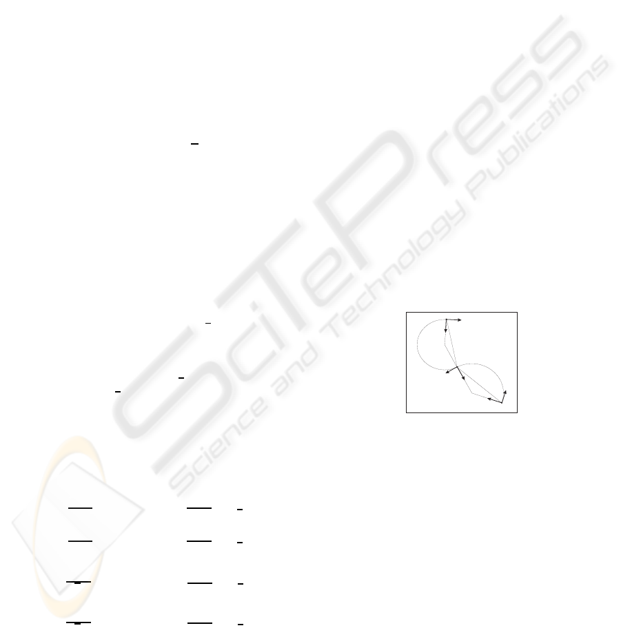
dom is to introduce an intermediate vertex such that
the line segment is replaced by two arc segments of
different curvature, as shown in figure 2. Hence two
t
s
t
I
t
f
n
s
n
I
n
f
v
I
v
s
v
f
q
s
q
f
r
s
r
f
a
s
a
f
Figure 2: Arc segment with C
2
contact intermediate vertex.
arcs of differing curvatures will connect the UAV ver-
tices via the intermediate vertex. In order to develop
the defining equations for such a solution, the inter-
section of two constant curvature arcs at a point with
C
2
contact is considered.
4 IMPLEMENTATION
AND RESULTS
The primary objective of the current work is to be
able to search the given unknown environment with
a swarm of UAVs to detect the region of the un-
known obstacles and to extract the shape of the ob-
stacle using 2-D Splinegon technique. Initially the
COOPERATIVE UAVS MAPPING COMPLEX ENVIRONMENT USING 2D SPLINEGON
415
circle packing algorithm is implemented that would
pack the required number of circles to fit in the given
environment. The search algorithm is employed with
the swarm of UAVs that would predict the next way
points in online using the neighboring way points or
it will follow the given set of POI to detect the obsta-
cles where the path of the vehicle is dictated by the
Dubins path planning algorithm. By fixing the de-
tecting sensor range, if any of the UAV is not able
to reach any given next way point, or if the obstacle
avoidance algorithm is activated so as to prevent the
UAV not reaching the given way point then that cir-
cle is added into the obstacle region. Once the search
is finished, depending upon the search region each of
the following requirements are taken by the decision
making algorithm.
• Find the area of the obstacle region.
• Find the required number of UAVs to accomplish
the mapping task. This can be done based on the
area of the obstacle region.
• Generate the way point for each of the UAVs to
perform the mapping task.
• Finally, find the shortest way points to each UAVs
to reach the starting point of the mapping task
from its current location.
As the vehicle moves each of the vehicle is localised
with an EKF. At the end of the each cycle (i.e., at
the completion of one way point) a local updated map
is constructed using the Splinegon technique. In the
case of more than one UAV is used in mapping, then
an intersection detection algorithm is implemented so
as to identify the state of the obstacle and to share the
sensor information with the other UAVs. Finally the
−100 −50 0 50 100 150
−100
−80
−60
−40
−20
0
20
40
60
80
100
x−coordinate in k.meters
y−coordinate in k.meters
X and Y coordinate in the map
1 2 3 4 5
6
7
8
9
10
11
12
13
14
15
16
17
18
19
20
21
22
23
24
25
26
27
28
29
30
31
32
33
34
35
36
37
38
39
40
41
42
43
44
45
46
47
48
49
50
51
52
53
54
55
56
57
58
59
60
61
62
63
64
65
66 67 68 69 70
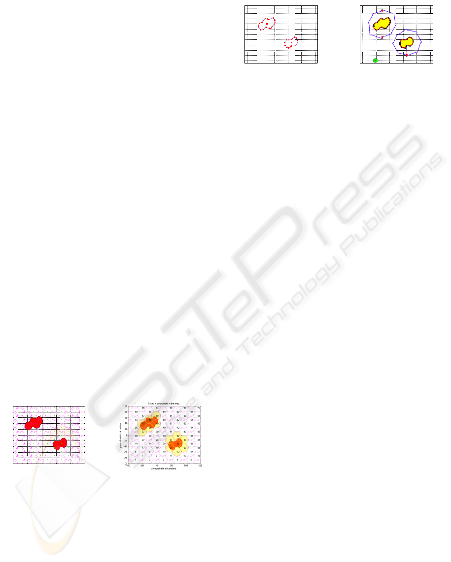
Figure 3: The results of the circle packing algorithm.
global updated map is constructed to get the map of
the unknown environment. The circles with radius R
c
which are packed in using circle packing algorithm
is shown in figure 2 (a). Then the search algorithm
is carried out by giving a set of point of intrust(POI)
way points to each of the UAVs so as to find the obsta-
cle region. The shaded circles where the UAVs could
not reach are known as the obstacle region which is
shown in figure 2 (b). At the end of the search algo-
rithm, the vehicle are switched from searching mode
−100 −50 0 50 100 150
−100
−80
−60
−40
−20
0
20
40
60
80
100
−100 −50 0 50 100 150
−100
−80
−60
−40
−20
0
20
40
60
80
100
x−coordinate in k.meters
y−coordinate in k.meters
X and Y coordinate in the map
Figure 4: The final updated map using Splinegon.
to the mapping the shape of the complex obstacle.
The local update is performed at the end of the each
way points. Finally the set of vertices that forms a
polygon with line segments in the final update and
the global updated map of the given unknown envi-
ronment is shown in figures 4 (a) and 4 (b).
5 CONCLUSIONS
In this paper the authors have described a novel, com-
putationally attractive, approach in estimating the lo-
calisation and mapping for curvilinear objects using
multiple UAVs. It enables to map obstacles of curvi-
linear shape, the data association for the networked
sensor platforms and the reactive tasking the UAVs.
Future work will extend the Splinegon technique to
3D in the robotic network that will enable the flight
paths to have even greater flexibility and will enable
the complex 3D shapes to be represented by a small
set of parameters.
REFERENCES
Dobkin, D. P. and Souvaine, D. L. (1990). Computational
geometry in a curved world. Algorithmica, 5(3):421–
457.
Dobkin, D. P., Souvaine, D. L., and Wyk, C. J. V. (1988).
Decomposition and intersection of simple splinegons.
Algorithmica, 3:473–485.
Guo, Y. and Qu, Z. (2005). Coverage control for a mobile
robot patrolling a dynamic and uncertain environment.
Proceedings of the 5th world Congress on Intelligent
Control and Automation, pages 4899–4903.
Kershner, R. (1939). The number of circles covering a set.
American Journal of Mathematics, 61(3):665–671.
Kreyszig, E. (1991). Differential geometry. Dover Publica-
tions, Inc., New York.
Washburn, A. R. (1981). Search and Detection. Millitry
Applications Section Operations Research Socitey of
America.
ICINCO 2009 - 6th International Conference on Informatics in Control, Automation and Robotics
416
