
COMPARISON BETWEEN MEXICAN HAT AND HAAR
WAVELET DESCRIPTORS FOR SHAPE REPRESENTATION
Adnan Abou Nabout and Bernd Tibken
Chair of Automatic Control, Faculty of Electrical, Information and Media Engineering
University of Wuppertal, Wuppertal, Germany
Keywords: Image Processing, Shape Representation, Wavelet Transformation, Wavelet Descriptors.
Abstract: The wavelet transformation is a well known method in several engineering fields. In image processing and
pattern recognition the wavelet transformation is used for the recognition of object shapes by deriving so
called wavelet descriptors. In this context the Mexican Hat as well as the Haar function were used as mother
wavelets. To derive wavelet descriptors the methods use a periodical angle function derived from the
contour polygon. The angle function describes an object shape by calculating the angle changes along the
object contour beginning from a given starting point. Since object shapes are described by polygons, the
angle function is step-shaped and therefore it includes discontinuity at the existing polygon corners. This
causes big changes of the Haar wavelet descriptors if the positions of the polygon corners change due to
small changes of the object shape. Such changes can be caused at least by digitalization or binarization
errors. The Mexican Hat wavelet descriptors are more adapted and suffer however from small changes. In
this paper we present the results of the comparison between both methods in there accurateness of
describing object shapes.
1 INTRODUCTION
The automatic recognition of objects, their
classification or representation is a very important
task in the field of image processing and pattern
recognition. In particular, the recognition of object
shapes is a commonly needed process in many
applications in this area (Grenander, Chow and
Keeman, 1991), (Belongie, Malik and Puzicha,
2001), (Fergus, Perona and Zisserman, 2003). The
recognition of weed species classes in agricultural
applications is one of the interesting examples for
the importance of object recognition using shape
information, since the shapes of weed species
change according to the growing stages of the weeds
(Nabout, Nour Eldin, Gerhards, Su and Kühbauch,
1994).
The most known method for the above
mentioned task uses the Fourier analysis (Zahn and
Roskies, 1972). The method is used to obtain a
number of coefficients, called Fourier descriptors
(FD) to describe a given object shape. The
recognition can be done through the comparison
between the FD of the unknown object with those of
the stored object samples using minimum distance or
Fuzzy methods (Nabout, 1993). In (Nabout and
Tibken, 2004, 2005, 2007 and 2008) we established
an alternative method using Wavelet transformation.
Similar to the FD we applied Wavelet descriptors
WD using the Mexican Hat or Haar function as
mother Wavelet.
In this paper we conclude the derivation of
wavelet descriptors for both cases and compare the
results of these different implementations in order to
find out the appropriate Wavelet building set. To
represent a given object shape we will show the right
way how to apply a periodical angle function using
the polygon data of a given object shape. This angle
function must be free from any singularity which
might arise due to object rotations. For that reason
the paper shows the derivation of the angle function
for a simple geometric object. To obtain a suitable
number of WD we normalized the angle function
over the interval
02π
and derived a wavelet
building set in the same interval. The results are
shown on the basis of different characters to
illustrate the different steps. We also present some
results related to the recognition of weed species in
plant fields. The paper is organized as follows:
214
Abou Nabout A. and Tibken B. (2009).
COMPARISON BETWEEN MEXICAN HAT AND HAAR WAVELET DESCRIPTORS FOR SHAPE REPRESENTATION.
In Proceedings of the 6th International Conference on Informatics in Control, Automation and Robotics - Robotics and Automation, pages 214-221
DOI: 10.5220/0002207002140221
Copyright
c
SciTePress
Section 2 addresses the derivation of the angle
function and describes the problem of singularity.
Section 3 introduces the continuous Wavelet
transformation. The derivation of the WD using
Mexican Hat as well as Haar function is presented in
section 4. In section 5 the results of applying the
new method are demonstrated and discussed. In this
context the minimum distance approach is described,
which is used to compare two different WD sets. In
section 6 the starting point problem is discussed.
2 SHAPE DESCRIPTION USING
AN ANGLE FUNCTION
To derive an angle function we use the polygon
information of a given object shape derived after
contour extraction and approximation (Nabout,
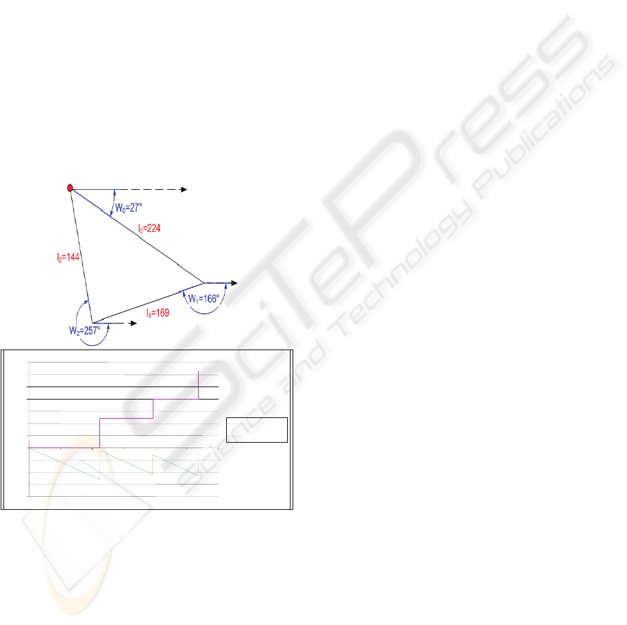
1993). Fig. 1 shows the example of a triangle shaped
object (a) and his derived angle (red) and periodical
angle functions (green) (b).
Figure 1: Polygon of triangle shaped object (a) and the
angle functions of the given shape (b).
To obtain the angle function we calculate the
angle differences between the absolute angles at
every position on the given polygon and the absolute
angle of the polygon at the starting point. It should
be noted that the starting point depends on the
object’s position and orientation in the image. The
calculation of the angle differences must take into
account that the absolute angles can change
according to the object rotation. In some cases small
object rotations cause significant changes in absolute
angles. We denote this problem as singularity
problem (Nabout, Tibken, 2008).
To avoid any singularity, we calculate all
absolute angles of the polygon edges with respect to
the x-coordinate as given in Fig. 1. The absolute
angles of a polygon edge P
P
are always positive
and can be computed using the polygon data as
follows:
if
x
!x
if
y
!y
{
ωtan
y
y
x
x
⁄
if
x
x
ωωπ
elseif
y
y
ωω2π
}
elseif
x
x
ω0,elseωπ
2
⁄
,32
⁄
where
x
,y
and
x
,y
are the coordinates
of the polygon corners P
and P
. To obtain the
angle function we then calculate the angle
differences as
α
ω
ω
if
α
π&α
2π
α
2πα
elseif
α
2π&α
π
α
2πα
elseα
α
where ω
is the absolute angle of the polygon edge
P
P
and ω
the absolute angle of the first polygon
edge P
P
. According to this definition, we obtain
for the example in Fig. 1.a the angle differences
0
,139
,230
, which correspond to the radian
values
0,2.4,4.0
as shown in Fig. 1.b.
The angle differences are negative in clockwise
direction. The angle function f
l
(red colored
function in Fig. 1.b) can be derived by calculating
the value of α for every position specified by the
parameter l, wherel is the contour length measured
from the starting point up to the current contour
position. The derived angle function is defined on
the interval
0,L
, where L is the total length
(circumference) of the given contour polygon and
can be scaled on the
0,2π
-interval using the
following parameter transformation:
,
⁄
(1)
with
⁄
(2)
we receive a periodical angle function (green
colored function in Fig. 1.b) f
t
with a period of
2π.
-
4,0
-
3,0
-
2,0
-
1,0
0
,0
1
,0
2
,0
3
,0
4
,0
5
,0
6
,0
7
,0
0
,0
1
00,0
2
00,0
3
00,0
4
00,0
5
00,0
6
00,0
3
.Angle_phi
3
. Angle _phi*
(b)
(a)
COMPARISON BETWEEN MEXICAN HAT AND HAAR WAVELET DESCRIPTORS FOR SHAPE
REPRESENTATION
215
3 WAVELET TRANSFORMATION
Similar to the FT, the WT uses elementary
functions, called wavelets, to describe a given
signal. In contrast to the FT, which uses harmonic
functions with different frequencies, the WT uses
only one basis wavelet (mother wavelet) to derive
the reconstruction signals (Daubechies 1992).
Through dilatation, compression and shifting of the
mother wavelet, we derive new variants of this
signal which together constitute the so-called
wavelet building set. Equation (3) describes the
general derivation of wavelets Ψ
,
t
from the
mother wavelet Ψ
t
(Daubechies, 1992).
Ψ
,
|
|
Ψ
tb
a
(3)
where a is the compression or dilatation parameter
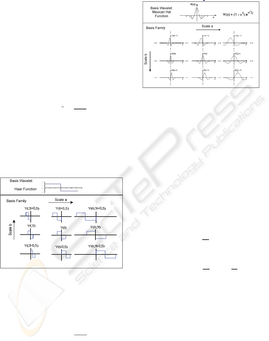
and b is the shifting parameter. Fig. 2 shows the
mother wavelet based on the Haar function and
some derived variants resulting from compression,
dilatation and shifting using (3). Fig. 3 shows the
equivalent Mexican Hat functions.
The function Ψ can be scaled over the interval
0,2π
similar to the periodic angle function.
Figure 2: Wavelet building set based on Haar function.
Based on (3), the following equation shows the
coefficient of the continuous Wavelet transformation
W
f
a,b
for the derived angle function f
t
given in (2).
,
|
|
⁄
Ψ
(4)
Figure 3: Wavelet building set based on Mexican Hat
function.
Replacing the function Ψ in (4) by the scaled
Haar function and setting the integration limits to
0,2π
, we obtain the following expression:
H
,
|
|
⁄
⁄
⁄
(5)
After executing the integrals in (5) we receive
the following expression:
H
,
|
|
⁄
2
2
4
(6)
where i, j, k are the indices of the polygon edges
according to the position of the current used Haar
function within the interval
0,2π
and α
are the
calculated angel differences (Nabout, Tibken, 2007).
Simlar to (5) we receive (7) when we replace the
function Ψ in (4) by the scaled Mexican Hat
function.
Ψ
1
0,0,5
1
0,5,1
0
ICINCO 2009 - 6th International Conference on Informatics in Control, Automation and Robotics
216
,
|
|
2
|
|
2
|
|
2
|
|
2
2
|
|
(7)
where
√
,
√
,
√
.
In (6) and (7) the terms which include the angle
differences α
are adequate to describe a given
object shape.
We denote W
H
f
a,b
as Haar Wavelet
descriptor (H-WD) and W
M
f
a,b
as Mexican Hat
Wavelet descriptor (MH-WD).
4 DERIVATION OF WAVELET
DESCRIPTORS
To obtain suitable WD for representing a given
object shape we vary the values of the compression
or dilatation parameter a and the shifting parameter
according to the following equations:
ar
2π
m
;bk
2π
m
(8)
withmlog
n
andn:numberofWD
r
1,2,,m
k
0,1,,m1
If we vary the parameter m as given in (8) we
obtain a sufficient Wavelet building within the
interval
0,2π
. For m6 is
a1
and (8) will
deliver only components of the approximation
signal. This signal describes the object shape
roughly. Detailed signal information that describes
small object shape changes can be derived for
m6 or through additional use of the reciprocal
values of a as given in (8). Generally only a few
number of WD (e.g. 32) is needed in practical
recognition applications to describe different object
shapes. In this case the parameter m can be set to 4 if
we use the reciprocal value of a to include
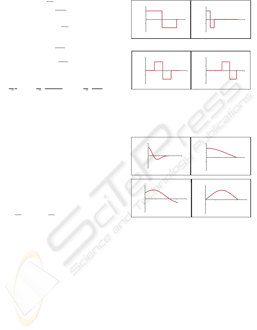
components of the detail signal. For m4, Fig. 4
shows a part of the Haar wavelet building set for
different parameter values.
1;04;0
2;12;2
Figure 4: Part of the Haar wavelet building set derived
within the interval
0,2π
.
Fig. 5 shows the corresponding Mexican Hat
wavelet building set for the same parameters.
Figure 5: Part of the Maxican Hat wavelet building set
derived within the interval
0,2π
.
As shown in these figures small values of the
parameter r produce compressed variants, big values
on the other hand create dilated variants of the
mother Wavelet. In both cases we receive an
approximation signal of the Wavelet transformation,
since a1. To receive components of the detail
signal which describes small details of the contour
shape we can use 1/a in combination with the same
values of b. For such values we obtain WD which
are qualified to describe small matches between the
compared shapes.
5 RESULTS
Fig. 7 shows the 16 MH- as well as H-WD obtained
from the approximation signal for the characters A
and B as shown in Fig. 6. The used starting points of
-1,5
-0,5
0,5
1,5
02468
-1,5
-0,5
0,5
1,5
02468
-1,5
-0,5
0,5
1,5
02468
-1,5
-0,5
0,5
1,5
0510
-1,5
-0,5
0,5
1,5
02468
-1,5
-0,5
0,5
1,5
02468
-1,5
-0,5
0,5
1,5
02468
-1,5
-0,5
0,5
1,5
02468
COMPARISON BETWEEN MEXICAN HAT AND HAAR WAVELET DESCRIPTORS FOR SHAPE
REPRESENTATION
217
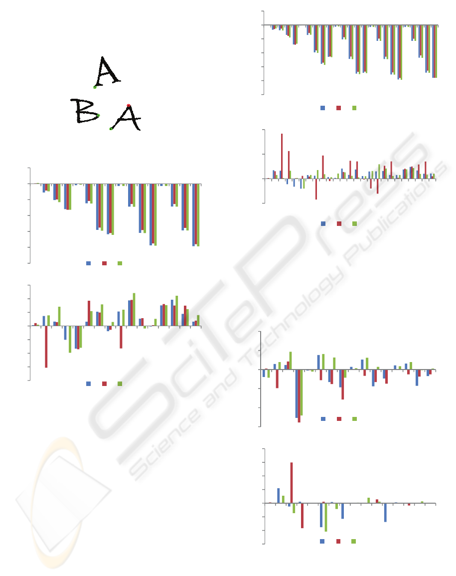
the derived angle functions are marked in Fig. 6 in
green colour. The dilatation or compress parameter a
and shifting parameter b are calculated as given in
(11) for r
1,2,3,4
andk
0,1,2,3
.
Figure 6: Example of an image with three characters.
Figure 7: The first 16 MH (a) and H-WD (b) for the
shapes of Fig. 6 obtained from the approximation signal.
As can be seen from Fig. 7 the differences
between the MH-WD of the approximation signal
are relatively small, the differences between the
corresponding values of the H-WD are on the other
hand large. This distinction is due to the
discontinuity of the angle function, which causes big
changes of the integration values in (6) when the
Haar function jumps from negative to positive or
positive to negative values. On the other hand the
MH-WD indicate a periodical behaviour, so that
only a few number of MH-WD of the approximation
signal are needed to represent the given object
shape. The H-WD on the other hand do not indicate
such behaviour. This property carries forward even
if we use different numbers of WD. Fig. 8 shows for
instance the results of 25 WD of the approximation
signal for r
1,2,3,4,5
andk
0,1,2,3,4
.
Figure 8: The first 25 MH and H-WD for the shapes of Fig.
6 derived from the approximation signal.
To study the detail signal we derived the 16 MH-
and H-WD obtained from the detail signal by using
the same parameter b and the reciprocal value of the
parameter a given before (Fig. 9).
Figure 9: The first 16 MH and H-WD for the shapes of
Fig. 6 derived from the detail signal.
The results in Fig. 9 indicate that the MH-WD of
the detail signal do not show any periodical
behaviour similar to the MH-WD of the
‐25
‐20
‐15
‐10
‐5
0
5
1 6 11 16
A B
A
‐20
‐15
‐10
‐5
0
5
10
15
1 6 11 16
A B
A
‐25
‐20
‐15
‐10
‐5
0
5
1 6 11 16 21
A B
A
‐20
0
20
40
1 6 11 16 21
A B
A
‐3
‐2
‐1
0
1
2
1 6 11 16
A B
A
‐30
‐20
‐10
0
10
20
30
40
1 6 11 16
A B
A
(b)
(a)
(b)
(a)
(b)
(a)
ICINCO 2009 - 6th International Conference on Informatics in Control, Automation and Robotics
218
approximation signal. On the other hand the values
of the detail signal are relatively small. In contrast to
the values of the MH-WD, the H-WD of the detail
signal show relatively large differences.
To compare the WD between different object
shapes we use the Euclidean distances d as given in
the following equation:
(9)
where WD
are the values of the Wavelet descriptors
for the first object shape and WD
are the values for
the second one.
The following table shows the distances between
the object shapes given in our example derived from
the approximation and detail signal separately.
Table 1: Euclidean Distances between the Object shapes
of Fig. 6 obtained from MH-WD and H-WD.
Approximation signal (MH-WD) (d
A
)
„A“ / „B“
2,48
„A“ / „A“
0,90
„A“ / „B“
2,74
Detail signal (MH-WD) (d
D
)
„A“ / „B“
2,35
„A“ / „A“
2,13
„A“ / „B“
3,22
Approximation signal (H-WD) (d
A
)
„A“ / „B“
25,42
„A“ / „A“
11,22
„A“ / „B“
27,86
Detail signal (H-WD) (d
D
)
„A“ / „B“
47,05
„A“ / „A“
20,81
„A“ / „B“
47,51
As shown in table 1 the distances between the
similar characters A and A are relatively small and
for the different characters A and B as well as A und
B on the other hand relatively large. Due to these
results it is possible to recognize the different object
shapes A und B using the minimum distance
method. In our example the characters can be
recognized using only the Euclidean distances of the
approximation signal. In many other applications it
is required to use also the detail signal to include
more detail information about the local changes of
the compared contour shapes.
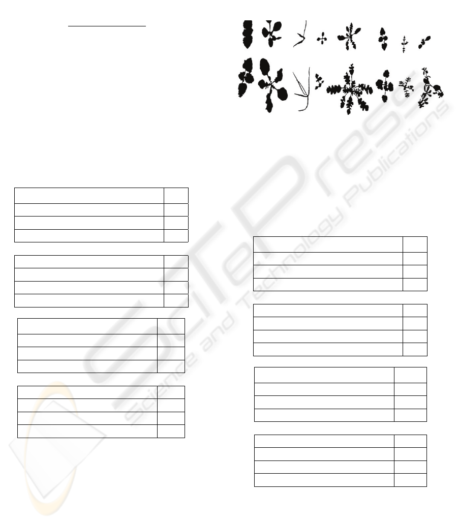
The following example shows the results of
applying the new method for the recognition of
weed species (Fig. 10).
Figure 10: Eight weed species in different growth stages.
Table 2 shows the minimum distances between
the WD of two different weeds using the WD
components of the approximation and detail signal.
Table 2: Euclidean Distances between the weed LAM and
MAT of Fig. 10 obtained from MH-WD and H-WD.
Approximation signal (MH-WD) (d
A
)
„LAM1“ / „LAM2“ 0,55
„LAM1“ / „MAT1“ 1,18
„LAM2“ / „MAT1“ 1,07
Detail signal (MH-WD) (d
D
)
„LAM1“ / „LAM2“ 1,77
„LAM1“ / „MAT1“ 5,00
„LAM2“ / „MAT1“ 5,52
Approximation signal (H-WD) (d
A
)
„LAM1“ / „LAM2“ 61,50
„LAM1“ / „MAT1“ 94,32
„LAM2“ / „MAT1“ 72,92
Detail signal (H-WD) (d
D
)
„LAM1“ / „LAM2“ 73,50
„LAM1“ / „MAT1“ 114,85
„LAM2“ / „MAT1“ 128,08
As shown in table 2 the weed can be recognized
correctly using the minimum distance method even
when we use either the approximation or the detail
signal alone. For some other weeds (VER and LAM)
the recognition process has failed.
VER1 THL1 POA1 STE1 CAP1 LAM1 MAT1 GAL1
VER2 THL2 POA2 STE2 CAP2 LAM2 MAT2 GAL2
COMPARISON BETWEEN MEXICAN HAT AND HAAR WAVELET DESCRIPTORS FOR SHAPE
REPRESENTATION
219
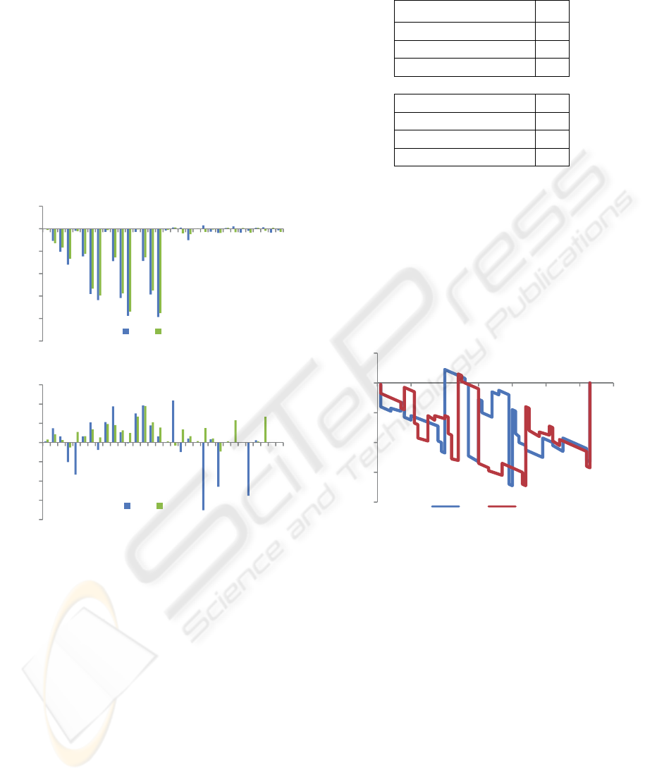
6 THE STARTING POINT
PROBLEM
The results of table 1 are obtained according to the
chosen starting points (green colored positions in
Fig. 6). If the starting points change, the angle
functions will also be changed and with them the
corresponding WD. If we change the starting point
of the character
A for instance from the green
colored position to the red one we receive for this
character the following MH-WD and H-WD values
(Fig. 11). Here both approximation and detail signals
are drown in the same diagram.
Figure 11: The MH-WD (a) and H-WD (b) for the
character A for the two different staring points given in
Fig. 6 derived from the approximation and detail signal.
As shown in Fig. 11 the change of the starting
point leads to large changes of the WD. Since the
position of the starting point in real applications
depends on several parameters, which cannot be
fixed, like position and rotation of the objects in the
image, number of objects, extraction method etc.,
the recognition process using the minimum distance
method will fail. Table 3 reports the Euclidean
distances between the given characters A and B
derived from the MH-WD for the new starting point
of the character A (red position). Using the H-WD
instead of the MH-WD indicates similar behavior.
Table 3: Euclidean Distances between the Objects of Fig.
6 derived from the MH-WD for the red starting point.
Approximation signal (d
A
)
„A“ / „B“
4,43
„A“ / „A“
6,86
„A“ / „B“
2,74
Detail signal (d
D
)
„A“ / „B“
2,73
„A“ / „A“
2,64
„A“ / „B“
3,22
As shown above the distances between the
characters with the similar shapes A and A are
higher than the distances between the different
shapes A and B as well as A and B. This is due to
the change of the angle functions within the interval
02π
according to the change of the starting
points. The following figure (Fig. 12) shows the
angle functions of the character A for the two
different starting points.
Figure 12: The angle functions of the characters A for two
different starting points.
As expected, the figure shows big differences of
the angle functions related to the change of the
starting point. Since the starting point on the contour
depends on several parameters of the image, the
above mentioned issue can cause confusion in
recognition tasks, because it is not explicit clear
whether big values of the Euclidean distance are
related to shape differences or to different starting
points. To solve this problem we use the following
strategy:
Suppose we have a number of object samples Oj
and an unknown object O which must be classified
to one of the given object classes. The procedure can
then be done as follows:
‐25
‐20
‐15
‐10
‐5
0
5
1 6 11 16 21 26 31
A_1 A_2
‐20
‐15
‐10
‐5
0
5
10
15
1 6 11 16 21 26 31
A_1 A_2
‐0,8
‐0,6
‐0,4
‐0,2
0
0,2
01234567
A_1 A_2
(a)
(b)
ICINCO 2009 - 6th International Conference on Informatics in Control, Automation and Robotics
220

• Calculate the WD of all objects O
j
for an
arbitrary starting point and store them in a
data base.
• Calculate the WD sets for all possible
starting points of the unknown object O. This
can be done easily if we use the polygon
description of the object contour and change
the starting point from one polygon corner to
the next.
• Compare the WD sets of the unknown object
separately with the stored WD of the object
samples using the minimum distance
method. We receive a number of Euclidean
distances
,
;1,2,…;1,2,…
according to the number of different starting
points
used in step 2 and the number of
object samples
given in step 1.
• Find the minimum value of
. The stored
object sample related to this minimum value
represents the recognized object.
7 CONCLUSIONS
The representation of object contours using wavelet
descriptors is useful in object recognition tasks. In
particular, the Mexican Hat as well as Haar function
are qualified to be used as a mother wavelet to
obtain a sufficient number of WD which can be used
in recognition tasks. The WD can be calculated very
easily using (6) for the H-WD and (7) for MH-WD.
The number of WD needed to recognize a given
object increases according to the complexity of the
object shapes and must be set according to the given
application. It is possible in some cases to use only
the components of the approximation signal in order
to recognize an unknown object using the minimum
distance method, but generally the use of the detail
signal will include detail information about small
differences between the compared object shapes.
The starting point on the contour has a big influence
on the recognition process, since the values of the
WD depend strongly on it. The paper describes one
possible solution where not only one set of WD is
computed and compared with the stored WD of the
object samples, but several sets of WD according to
the different starting points.
REFERENCES
Grenander, U., Chow, Y. and Keenan, D. M., 1991.
HANDS: A Pattern Theoretic Study Of Biological
Shapes. Springer Verlag.
Belongie, S., Malik, J. and Puzicha, J., 2001. Matching
shapes, In ICCV, pp. I.454-461.
Fergus, R., Perona, P. and Zisserman, A., 2003. Object
class recognition by unsupervised scale-invariant
learning. In CVPR, pp. 264-271.
Nabout, A., Nour Eldin, H.A., Gerhards, R., Su, B.,
Kühbauch, W., 1994. Plant Species Identification
using Fuzzy Set Theory, pp. 48-53, Proc. of the IEEE
Southwest Symposium on Image Analysis and
Interpretation, Dallas, Texas, USA.
Zahn, C., Roskies, R. Z., 1972. Fourier descriptors for
plant closed curve, IEEE Trans. On C-21.
Nabout, A., 1993. Modular Concept and Method for
Knowledge Based Recognition of Complex Objects in
CAQ Applications, VDI Publisher, Series 20, No. 92.
Nabout, A., Tibken, B., 2004. Object Recognition Using
Polygons and Wavelet Descriptors, 1st International
Conference on Information & Communication
Technologies, Proceedings of ICTTA'04, April 19 -
23, Damascus, Syria.
Nabout, A., Tibken, B., 2005. Wavelet Descriptors for
Object Recognition Using Mexican Hat Function, 16th
IFAC World Congress, Prague, Czech Republic.
Nabout, A., Tibken, B., 2007. Object Shape Recognition
using Mexican Hat Wavelet Descriptors, 2007 IEEE
International Conference on Control and Automation,
Guangzhou, CHINA - May 30 to June 1, pp. 1313-
1318.
Nabout, A., Tibken, B., 2008. Object Shape Description
Using Haar-Wavelet Functions, the 3rd IEEE
International Conference on Information &
Communication Technologies: from Theory to
Application, ICTTA'08, 7-11 April 2008, Umayyad
Palace, Damascus, Syria.
Daubechies, I., 1992. Ten Lectures on Wavelets, Society
for Industrial & Applied Mathematics.
COMPARISON BETWEEN MEXICAN HAT AND HAAR WAVELET DESCRIPTORS FOR SHAPE
REPRESENTATION
221
