A NOVEL HAPTIC INTERFACE FOR EXTENDED RANGE
TELEPRESENCE
Control and Evaluation
Antonia P
´
erez Arias and Uwe D. Hanebeck
Intelligent Sensor-Actuator-Systems Laboratory (ISAS)
Institute for Anthropomatics
Universit
¨
at Karlsruhe (TH), Germany
Keywords:
Extended range telepresence, Motion compression, Haptic interface, Force control.
Abstract:
A novel haptic interface for extended range telepresence is presented that allows the user simultaneous wide
area motion and haptic interaction in remote environments. To achieve an extended workspace, the haptic
interface consists of a haptic manipulator for precise haptic rendering and a large portal carrier system that
enlarges the workspace by prepositioning the end-effector. As the prepositioning unit is grounded and driven
by three linear drives, our approach has the advantages of high force capability and an accurate positioning of
the haptic interface. The use of this haptic interface with Motion Compression permits to explore large remote
environments even from small user environments. As a result, not only has the user visual, acoustic, and haptic
feedback, but can also control the teleoperator or avatar by natural walking, which considerably increases the
sense of immersion. A prototype system for haptic extended range telepresence was designed, implemented,
and tested.
1 INTRODUCTION
Telepresence aims at creating the impression of be-
ing present in an environment, which is inaccessible
to a human user. Such an environment can be real or
virtual, and will be referred to in the following as tar-
get environment. The feeling of presence is achieved
by visual and acoustic sensory information recorded
from the target environment and presented to the user
on an immersive display.
The more of the user’s senses are involved, the
better the immersion in the target environment. In
order to use the sense of motion as well, which is
especially important for human navigation and way
finding, the user’s motion can be tracked and trans-
ferred to the teleoperator, a mobile robot or an avatar,
in the target environment. As a result, in extended
range telepresence the user can additionally use the
proprioception, the sense of motion, to navigate the
teleoperator by natural walking, instead of using de-
vices like joysticks, pedals or steering wheels.
However, without further processing the motion
information, the motion of the user is restricted to
the size of the user environment, which is limited, for
example by the range of the tracking system or the
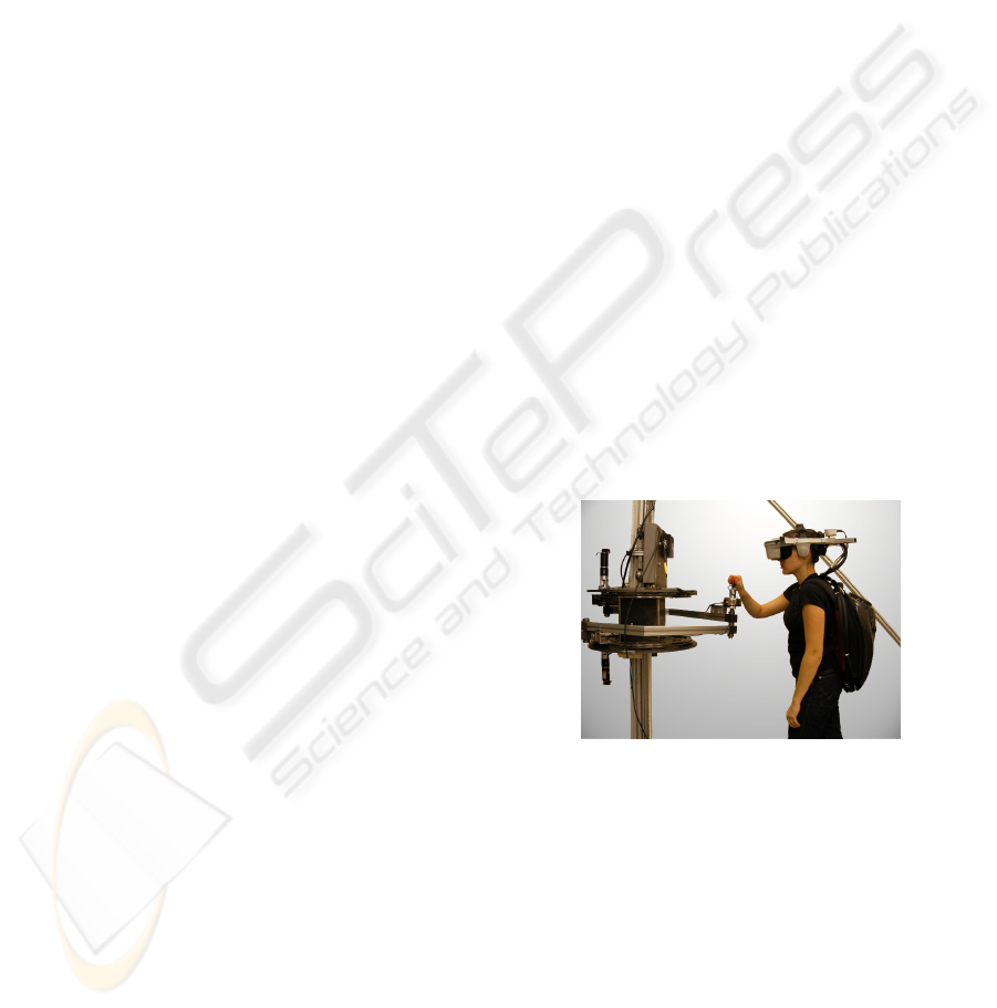
Figure 1: User and haptic interface for interaction with ex-
tended target environments.
available space. Motion Compression (Nitzsche et al.,
2004) is an algorithmic approach that provides a non-
linear transformation, mapping the path in the target
environment to a feasible path in the user environment
by minimizing proprioceptive and visual inconsisten-
cies.
Extended range telepresence can be applied in
many fields, especially in those that require the human
navigation skills to solve the task, for example tele-
exploration of remote environments, visualization of
complex structures, training of emergency evacua-
tions, etc. An extended range telepresence system
222
Pérez Arias A. and D. Hanebeck U. (2009).
A NOVEL HAPTIC INTERFACE FOR EXTENDED RANGE TELEPRESENCE - Control and Evaluation.
In Proceedings of the 6th International Conference on Informatics in Control, Automation and Robotics - Robotics and Automation, pages 222-227
DOI: 10.5220/0002208802220227
Copyright
c
SciTePress

that uses Motion Compression to teleoperate a mo-
bile robot is presented in (R
¨
oßler et al., 2005). Since
haptic information is indispensable, amongst others,
for haptic exploration and manipulation of objects in
the target environment, a novel haptic interface for the
extended range telepresence system was built. A pic-
ture of the system is shown in Fig. 1.
Force reflecting telepresence systems usually as-
sume an immobile user and a restricted workspace.
For example, industrial robots have often been used
as haptic interfaces due to their accuracy and relative
high force capability (Hoogen and Schmidt, 2001)
but their limited workspace makes them unfeasible
for extended range telepresence. In the last years,
several haptic interfaces that allow a dexterous feed-
back and fairly high forces have been designed to en-
large their workspaces, e.g. a string-based haptic in-
terface (Bouguila et al., 2000), or a grounded hyper-
redundant haptic interface in (Ueberle et al., 2003).
Portable haptic interfaces like exoskeletons (Bergam-
asco et al., 1994) solve the problem of wide area mo-
tion, since the interface is carried along by the user.
However, working with exoskeletons can be fatiguing
for the user due to the high weight of the system. In
addition, they can display lower forces than grounded
displays (Richard and Cutkosky, 1997). The only
group of systems that really allow haptic interaction
during wide area motion are mobile haptic interfaces
(Nitzsche et al., 2003), (Formaglio et al., 2005), (Peer
et al., 2007). These are usually small haptic devices
mounted on a mobile platform. Drawbacks of such in-
terfaces are a difficult control and a dependency of the
force display quality on the localization of the mobile
platform.
In this paper, we present a novel haptic device that
allows haptic interaction in extended range telepre-
sence and combines the advantages of grounded and
mobile haptic interfaces. It consists of a grounded lin-
ear prepositioning unit that moves along with the user
and a manipulator arm attached to the prepositioning
unit that is used to display forces at any position in the
user environment. This haptic interface allows in con-
junction with Motion Compression unrestricted wide
area motion and the possibility of effectively guiding
the user in the target environment by means of hap-
tic information. The control of the haptic interface is
based on the decoupling of force control and preposi-
tioning of the haptic device, which takes both the op-
timal manipulator’s configuration and the user’s posi-
tion into consideration.
The remainder of this paper proceeds as follows.
The following section presents the extended range te-
lepresence system. Motion Compression is reviewed,
since it determines the requirements of the haptic in-
terface, and the mechanical setup of the haptic inter-
face is presented. In section 3, a detailed description
of the control design is given. Experimental results
are shown in section 4. Finally, a summary and an
outlook can be found in section 5.
2 EXTENDED RANGE
TELEPRESENCE SYSTEM
2.1 Motion Compression
Motion Compression provides a nonlinear mapping
between the user’s path in the user environment and
the path in the target environment. It consists of three
modules: Path prediction tries to predict the desired
path of the user in the target environment by means
of tracking data and, if possible, information of the
target environment. The resulting path is called target
path. Path transformation transforms the target path
so that it fits in the user environment. The resulting
user path conserves the length and turning angles of
the target path while there is a minimum difference in
curvature. Fig. 2 shows these paths in both environ-
ments. Finally, the user guidance module guides the
user on the user path, while he has the impression of
walking on the original target path.
4 m
4 m
8 m
7 m
User Environment Target Environment
Figure 2: The corresponding paths in both environments.
Left: user path in the user environment. Right: target path
in the target environment.
The result of Motion Compression is a trans-
formation between the user’s position in the user en-
vironment and the teleoperator’s position in the tar-
get environment at any time and position. This trans-
formation can also be used to map the user’s hand po-
sition, or to transform force vectors recorded by the
teleoperator back into the user environment.
The use of Motion Compression for extended
range telepresence puts a number of demands on the
design of a haptic interface. The haptic interface must
be able to reach all configurations in a user environ-
ment of 4 × 4 m
2
, in which the user may move with a
natural speed of up to 2 m/s. Especially the rotational
motion around the vertical axes must be unlimited.
A NOVEL HAPTIC INTERFACE FOR EXTENDED RANGE TELEPRESENCE - Control and Evaluation
223
2.2 A Novel Haptic Interface: Setup
Fine haptic rendering and wide area motion require
very different characteristics regarding mechanics as
well as control. Therefore a novel haptic interface
was designed that consists of two subsystems: a linear
prepositioning unit that accompanies the user along
the user path so that he does not perceive the haptic
display, and a manipulator arm attached to the prepo-
sitioning unit that is used to display defined forces at
any position in the user environment. In this way, the
workspace of the haptic interface covers the whole
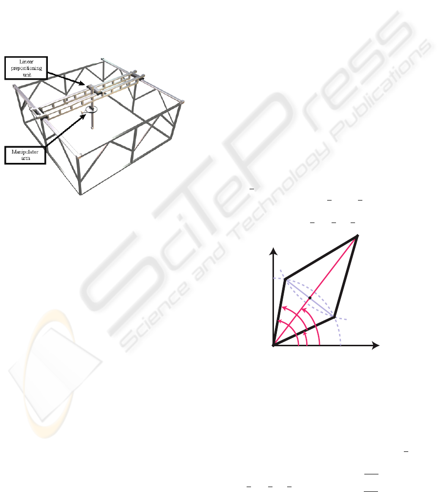
user environment. Fig.3 shows a CAD drawing of the
complete setup.
Figure 3: CAD drawing of the complete setup with linear
positioning unit and manipulator arm.
The motion subsystem is realized as grounded
portal carrier system of approximately 5 × 5 × 2 m
3
with three translational degrees of freedom, which are
realized by three independent linear drives. These
linear drives are built using a commercially available
carriage-on-rail system. The carriages are driven by a
toothed belt. The x- and y-axis consist of two parallel
rails each for stability reasons, while the z-axis is only
a single rail. As a result, the system is driven by five
synchronous AC-motors with helical-bevel servo gear
units of 120 Nm maximal torque, that allow a maxi-
mum speed of 2 m/ s and an acceleration of 2 m/ s
2
.
As the configuration space equals cartesian space, for-
ward kinematics can be expressed by means of an
identity matrix. Thus position control is extremely
easy to handle and very robust (R
¨
oßler et al., 2006).
This construction has the advantages of a a high
force capability and an accurate positioning of the
manipulator, which is determined directly through en-
coder’s information with relative accuracy 0.1 mm.
By using a position control with high gains, the
user does not perceive the motion subsystem, and
the transparency depends only on the force-controlled
subsystem (Nitzsche et al., 2003).
Because the acceleration of the human hand is typ-
ically much higher than the acceleration of the portal
carrier, a fast manipulator was used. It covers the hu-
man arm workspace and has planar movement. It is
implemented as a planar SCARA arm, which is at-
tached to the z-axis of the portal carrier. The redun-
dant planar degrees of freedom permit the separation
of positioning and force display. Two active rotational
joints driven by two 150 W DC-motors are integrated
into the base, so that all moving joints are passive.
Circular drives allow infinite motion around the z-
axis. The manipulator arm was designed to display
a force of 50 N at the end-effector. More details can
be found in (R
¨
oßler et al., 2006).
3 CONTROL DESIGN OF THE
HAPTIC INTERFACE
3.1 Kinematic Model
The control of this haptic interface is based on the de-
coupling of force control at the end-effector and po-
sition control of the haptic device. The position of
the end-effector with respect to the basis coordinate
frame x
E
is described by the global position of the
linear prepositioning unit, x
L
, and x
S
, the relative po-
sition of the manipulator arm with respect to the linear
prepositioning unit as x
E
= x
L
+ x
S
.
α
ψ
β
L
E
x
y
R
l
2
l
1
ϕ
Figure 4: Geometrical SCARA-Model.
Fig. 4 shows the geometrical SCARA-model used
to derive the kinematic equations. L represents the
linear prepositioning unit, E the end-effector, and l
1
and l
2
the lengths of the inner and outer segments,
respectively. If only the joints at the angles α and β
are actively driven, the end-effector position x
E
can
be expressed as
x
E
= x
L
+ x
S
=
x
L
y
L
+
cos
α+β
2
·R
sin
α+β
2
·R
, (1)
ICINCO 2009 - 6th International Conference on Informatics in Control, Automation and Robotics
224

where R, the radial travel, is calculated as
R = l
1
cos
β −α
2
+
s
l
2
2
− l
2
1
sin
2
β −α
2
(2)
With this equation the direct kinematics of the ma-
nipulator is defined. The Jacobian of the manipulator
J(γ) on the configuration space γ =
α β
T
, which
will be used next for the control of the haptic inter-
face, is defined as
J
γ
=
∂x
S
γ
∂γ
(3)
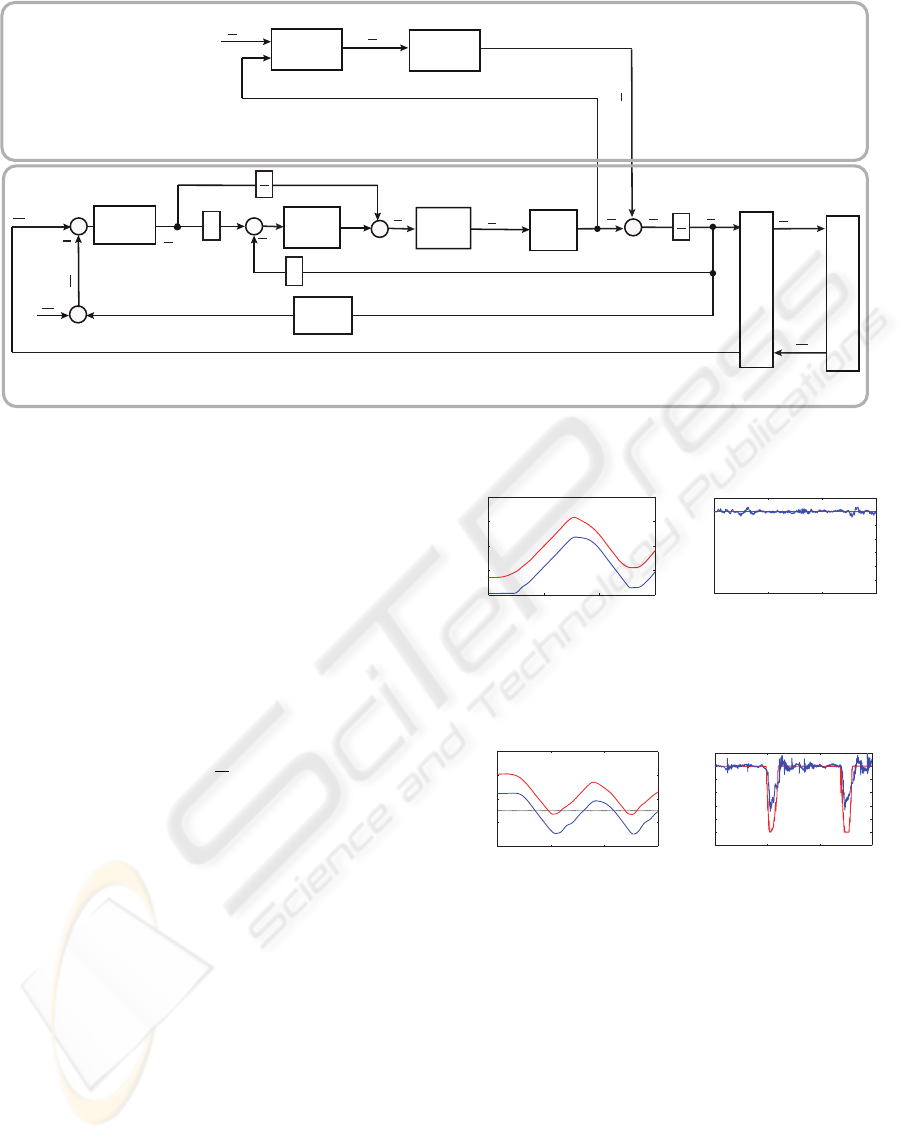
3.2 Control Structure
Fig. 5 illustrates the block diagram of the control
scheme with force feedback, as well as the position
control of the haptic display. The end-effector ve-
locity of the haptic interface ˙x
E
is transmitted via the
communication channel and acts as reference velocity
at the end-effector of the teleoperator ˙x
E,re f ,T
. The en-
vironment reacts according to its impedance with a re-
action F
T
, which is measured by the teleoperator, and
transmitted to the haptic interface as reference input
F
T,re f ,U
. This architecture represents a two-channel
force-velocity bilateral control.
In our system, the haptic interface is modelled as
an admittance, which transforms F
U,re f
, the reference
force to be displayed, into the reference motion of the
end-effector as
F
U,re f
= M · ¨x
E,re f
+ D· ˙x
E,re f
, (4)
where M is the desired mass matrix and D the de-
sired damping matrix. The admittance control scheme
is very well suited for systems with nonlinearities
and large dynamic properties because the admittance
model shapes the desired dynamic behaviour of the
system by compensating the natural device dynamics
(Ueberle and Buss, 2004).
The resolved acceleration control (J
−1
control) is
applied to calculate the commanded motor torque of
the manipulator τ
re f
:
τ
re f
=
ˆ
M ·J
−1
· ¨x
C
+ h
γ,
˙
γ
·
˙
γ +g
γ
, (5)
where
ˆ
M is an approximation of the device joint iner-
tia matrix and J is the Jacobian. The vectors h, repre-
senting the friction effects, and g can be approximated
through experimental identification.
The user, while moving the end-effector, applies a
force consisting of a voluntarily applied force and a
reaction force induced by the arm impedance. In or-
der to reconstruct the applied force from the measured
force F
∗
U
and the velocity of the end-effector, a model
of the human arm impedance is applied:
F
U
= F
∗
U
+ M
u
· ¨x
E
+ D
u
· ˙x
E
+ K
u
·x
E
(6)
It is known that the arm impedance varies with the
user and the arm configuration. Hence, the mean val-
ues of multiple users and planar configurations were
used: M
u
= 2 Kg, D
u
= 6 Ns/m, and K
u
= 10 N/ m.
The reference position of the linear prepositioning
unit x
L,re f
, which can be easily controlled in cartesian
coordinates, is calculated by optimizing the manipu-
lator’s configuration according to some performance
measure.
3.3 Prepositioning
When attaching the SCARA manipulator to the portal
carrier, there is a redundancy in the planar directions
that may be resolved by optimizing the manipulabil-
ity of the SCARA. The manipulability is usually rep-
resented as
w
γ
=
r
det
J
T
(γ)·J(γ)
. (7)
For l
1
= 0.285 m and l
2
= 0.708 m, the SCARA
robot’s manipulability was found to be optimal when
ψ = β − α = 2.048.
Let’s consider the polar coordinates of
the end-effector’s position: R = l
1
cos
ψ
2
+
q
l
2
2
− l
2
1
sin
2
ψ
2
, and φ =
α+β
2
. Since the manipu-
lability w is independent of φ, another criterion must
be found to optimize this parameter. It is also crucial
to avoid collisions with the user, therefore the angle
φ is chosen that maximizes the distance d between
the user and the prepositioning unit by adopting
R
opt
= R(ψ
opt
). By designating x
EH
the vector from
the end-effector’s position to the user’s position, and
θ the angle between this vector and the x-axis, the
distance d can be expressed as
d = R
opt
2
+
|
x
EH
|
2
− 2R
|
x
EH
|
cos(θ −φ + π) , (8)
and it is maximal when φ
opt
= θ, or in other words,
when the linear prepositioning unit is situated in front
of the user, and lies on the connecting line between
the user’s head and the end-effector. The optimal joint
angles are finally α
opt
= φ
opt
−
ψ
opt
2
and β
opt
= φ
opt
+
ψ
opt
2
.
With x
opt
S
=
cos(φ
opt
)·R
opt
sin(φ
opt
)·R
opt
T
being the optimal configuration of the manipulator,
the reference position of the linear prepositioning re-
sults x
L,re f
= x
E
− x
opt
S
.
A NOVEL HAPTIC INTERFACE FOR EXTENDED RANGE TELEPRESENCE - Control and Evaluation
225
Teleoperator
Simulation
Position
Controller
Position
Optimization
Position Control
Force Control
F
T,ref,U
F
U
F
∗
U
F
T
x
S
τ
ref
x
L,ref
x
H
x
L
Communication &
Motion Compression
Admittance
Model
x
C
d
dt
Arm
Impedance
Position
Controller
Inverse
Dynamics
Haptic
Display
d
dt
˙x
E,ref,T
˙x
E
x
E
˙x
E,ref
Figure 5: Control scheme of the haptic interface.
4 EXPERIMENTS
Two kinds of experiments were performed in order
to evaluate the proposed haptic interface. First, the
proposed force control was tested and second, the si-
multaneous wide area motion with haptic interaction
was validated.
The force at the end-effector, and the positions
of both, end-effector and prepositioning unit, were
recorded during free motion and during a hard con-
tact. In order to achieve transparency, the reference
force during free motion is F
U,re f
= 0 N. An admit-
tance of M = 4 kg was simulated. The control gains
of the prepositioning and the admittance position con-
troller were obtained experimentally using standard
Ziegler-Nichols.
Fig. 6 shows the force-position plots for the x-
direction, when a user walks 15 seconds back and
forth about 2 m in x-direction. Analogously, Fig. 7
represents the reference and the measured force when
a user walks against a wall at position −0.5 m with
rigidity K = 700 N/m. The maximal displayed force
is limited to 60 N. Both figures also show the motion
of the linear positioning unit at an optimal distance of
the end-effector.
The main advantage of the admittance control is
that the desired mass and damping of the device can
be shaped. However, it is known that the admittance
control reduces the force bandwidth of the haptic sys-
tem.
The prepositioning was tested together with the
haptic interaction to validate the entire concept of the
haptic interface. For this purpose, the virtual and
0 5 10 15
−2
−1
0
1
2
t/s
x/
m
(a)
0 5 10 15
−120
−100
−80
−60
−40
−20
0
20
t/s
F
x
/N
(b)
Figure 6: Position and force during free motion. (a) End-
effector position x
E
(red), linear system position x
L
(blue).
(b) Reference force F
x,re f
= 0 N (red), actual force F
x
(blue).
0 5 10 15
−2
−1
0
1
2
t/s
x
/
m
(a)
0 5 10 15
−120
−100
−80
−60
−40
−20
0
20
t/s
F
x
/N
(b)
Figure 7: Position and force by hard contact. (a) End-
effector position x
E
(red), linear system position x
L
(blue).
(b) Reference force F
x,re f
(red), actual force F
x
(blue).
the user environment were supposed coincident, i.e.
4 × 4 m
2
large, and two virtual walls were placed in-
side. Fig. 8 shows the results of this experiment. The
motion of the user can be divided into four segments:
a) the user moves toward the wall, b) the user walks
along the wall 1, c) the user walks along the wall 2,
and d) the user turns on place. The haptic interface is
always on the opposite side of the end-effector, so that
the danger of a collision with the user is avoided. At
the same time, the distance between the end-effector
and the basis of the haptic interface is kept constant
ICINCO 2009 - 6th International Conference on Informatics in Control, Automation and Robotics
226
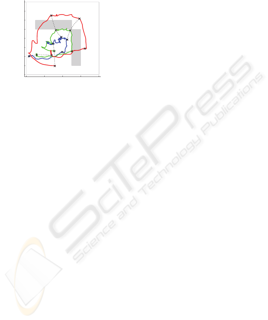
on the optimal value that maximizes the manipulabil-
ity of the haptic display.
−2 −1 0 1 2
−2
−1.5
−1
−0.5
0
0.5
1
1.5
2
x /m
y /
m
a
b
c
d
Wall 1
Wall 2
Figure 8: Positions of user x
H
(blue), end-effector x
E
(green) and linear system x
L
(red) in presence of virtual
walls during wide area motion.
5 CONCLUSIONS
This paper presents a novel multi-modal telepresence
system for extended range telepresence, which en-
ables the user to explore remote environments by nat-
ural walking. To achieve this goal, a novel haptic in-
terface was developed, which consists of a haptic ma-
nipulator mounted on a linear prepositioning unit that
follows the user by keeping the optimal configuration
of the manipulator and avoiding collisions with the
user. For the haptic feedback, a dedicated force con-
trol was implemented and tested. It uses an admit-
tance model to shape the dynamics of the system, as
well as a model of the impedances of arm and mani-
pulator to compensate their undesired dynamics. Ex-
periments show the suitability of this haptic interface
for extended range telepresence.
The use of haptic information in extended range
telepresence to improve the user guidance is a promis-
ing application of the presented haptic interface,
which is currently being investigated. For this ap-
plication, the simultaneous compression of head and
hand motion represents a further challenge.
REFERENCES
Bergamasco, M., Allotta, B., Bosio, L., Ferretti, L., Perrini,
G., Prisco, G. M., Salsedo, F., and Sartini, G. (1994).
”An arm exoskeleton system for teleoperation and vir-
tual environment applications”. In Proceedings of the
IEEE Intl. Conference on Robotics and Automation.
Bouguila, L., Ishii, M., and Sato, M. (2000). ”Multi-modal
haptic device for large-scale virtual environment”. In
Proceedings of the 8th ACM Intl. Conference on Mul-
timedia.
Formaglio, A., Giannitrapani, A., Barbagli, F., Franzini, M.,
and Prattichizzo, D. (2005). ”Performance of mobile
haptic interfaces”. In Proceedings of the 44th IEEE
Conference on Decision and Control and the Euro-
pean Control Conference.
Hoogen, J. and Schmidt, G. (2001). ”Experimental results
in control of an industrial robot used as a haptic inter-
face”. In Proceedings of the IFAC Telematics Appli-
cations in Automation and Robotics.
Nitzsche, N., Hanebeck, U. D., and Schmidt, G. (2003).
”Design issues of mobile haptic interfaces”. Journal
of Robotic Systems, 20(9):549–556.
Nitzsche, N., Hanebeck, U. D., and Schmidt, G. (2004).
”Motion compression for telepresent walking in large
target environments”. Presence, 13(1):44–60.
Peer, A., Komoguchi, Y., and Buss, M. (2007). ” Towards a
mobile haptic interface for bimanual manipulations”.
In Proceedings of the IEEE/RSJ Intl. Conference on
Intelligent Robots and Systems.
Richard, C. and Cutkosky, M. R. (1997). ”Contact force
perception with an ungrounded haptic interface”. In
Proceedings of ASME IMECE 6th Annual Symposium
on Haptic Interfaces.
R
¨
oßler, P., Armstrong, T., Hessel, O., Mende, M., and
Hanebeck, U. D. (2006). ”A novel haptic interface for
free locomotion in extended range telepresence sce-
narios”. In Proceedings of the 3rd Intl. Conference on
Informatics in Control, Automation and Robotics.
R
¨
oßler, P., Beutler, F., Hanebeck, U. D., and Nitzsche, N.
(2005). ”Motion compression applied to guidance of
a mobile teleoperator”. In Proceedings of the IEEE
Intl. Conference on Intelligent Robots and Systems.
Ueberle, M. and Buss, M. (2004). ”Control of kinesthetic
haptic interfaces”. In Proceedings of the IEEE/RSJ
Intl. Conference on Intelligent Robots and Systems,
Workshop on Touch and Haptics.
Ueberle, M., Mock, N., and Buss, M. (2003). ”Towards
a hyper-redundant haptic display”. In Proceedings of
the International Workshop on High-Fidelity Telepre-
sence and Teleaction.
A NOVEL HAPTIC INTERFACE FOR EXTENDED RANGE TELEPRESENCE - Control and Evaluation
227
