
SCHEME FOR EVALUATION AND REDUCTION OF MOTION
ARTIFACTS IN MOBILE VISION SYSTEMS
Christoph Walter
1
, Felix Penzlin
2
and Norbert Elkmann
1
1
Fraunhofer Institute for Factory Operation and Automation
Sandtorstrasse 22, 39106 Magdeburg, Germany
2
Otto-von-Guericke-University Magdeburg
Universitätsplatz 2, 39106 Magdeburg, Germany
Keywords: Vision, Motion Blur, Mobile Robot, Congestion Control.
Abstract: Artifacts like motion blur are a common problem for vision systems on mobile robots, especially when
operating under low light conditions or when using high-resolution sensors. In this contribution we present a
scheme for estimating the degree of motion artifacts, especially motion blur, present in a stream of
individual camera images. A single quality estimate is derived per frame using data from an inertial
measurement unit. Considering limited image processing capacity of resource-constrained mobile robots,
we show a number of data processing strategies that are based upon the idea of congestion control by
adaptive image rejection.
1 INTRODUCTION
While the presence of motion artifacts in images
from moving cameras can also be exploited in
several ways, it is usually a troublesome effect.
Objects may become unrecognizable because of
blur; visual SLAM algorithms may yield poor results
because of difficulties when finding corresponding
image points or due to geometric distortion of the
whole image.
At the same time, image processing tasks usually
require significant resources and may easily exceed
the capabilities of the computer hardware present on
a mobile robot.
In the following sections we describe our
approach to lessen the effects of both problems. At
first we evaluate motion artifacts in greater detail.
After discussing related work we present our method
for estimating the image quality regarding the
presence of motion artifacts. We then show data
processing strategies including an approach to
congestion control in persistent overload situations.
We also present improvements of a specific vision
task achieved with our system.
2 MOTION ARTIFACTS
Cameras acquire images by exposing a light-
sensitive element for a given period of time. Camera
movement while the sensor is exposed may result in
a number of image artifacts. Lens distortion is
considered to have a negligible impact and is
therefore not modeled here.
2.1 Motion Blur
Motion blur can be induced by moving either objects
in the camera’s field of vision or the camera itself.
For simplicity we consider only a static scene and
disregard any moving objects.
Camera Translation. We distinguish between two
kinds of camera movement. On the one hand there is
translation in direction of the optical axis; on the
other hand there is motion in the plane orthogonal to
that axis. In the second case, the magnitude of blur b
on the image sensor for an object is in inverse
proportion to the distance to the camera plane d
cam
(See Figure 1).
238
Walter C., Penzlin F. and Elkmann N. (2009).
SCHEME FOR EVALUATION AND REDUCTION OF MOTION ARTIFACTS IN MOBILE VISION SYSTEMS.
In Proceedings of the 6th International Conference on Informatics in Control, Automation and Robotics - Robotics and Automation, pages 238-243
DOI: 10.5220/0002209102380243
Copyright
c
SciTePress
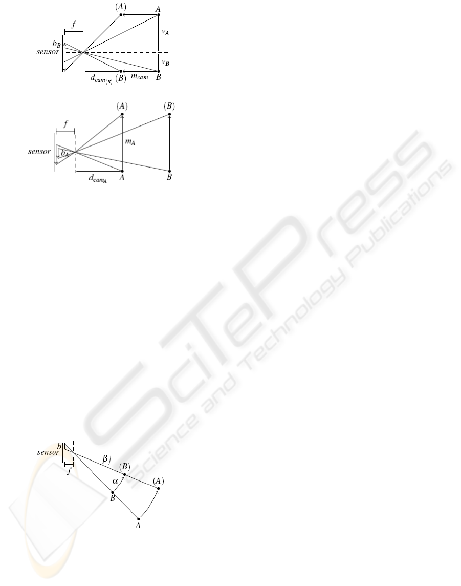
Figure 1: Motion blur in case of translation parallel to the
optical axis (upper part) and vertical or horizontal
translation (lower part).
For movements parallel to the optical axis the
intensity of blur b for an object depends on its
distances from line of view v and camera plane d
cam
and the displacement m
cam
. For a point at the optical
axis, this kind of translation has no impact. If objects
are relatively far away from the camera, translation
becomes insignificant.
Camera Rotation. When rotating the camera, the
magnitude of blur also depends on the position of a
given object relative to the optical axis. Figure 2
shows that such a camera rotation results in a blur b
roughly perpendicular to the axis of rotation. Its
strength depends on the actual angle of rotation and
on the angle between the rotation axis and the view
direction. The distance to an object does not matter
for rotational blur (See Figure 2).
Figure 2: Motion blur in case of rotation.
2.2 Distortion
Geometrical image distortion is another common
artifact that can be found with moving cameras. It
occurs when different portions of the image sensor
are exposed sequentially to light. This “rolling
shutter”-mode is implemented in a number of
CMOS-based cameras.
A sudden change in illumination may influence
only portions of the image. If the camera is moved
horizontally or rotated around the vertical axis, skew
can be observed. Vertical lines appear to lean to the
left for moving to the left or the right side for the
opposite direction of movement. Vertical
movements as well as rotations around the
horizontal axis result in stretching respectively
shrinking of objects vertically. Altering the direction
of movement at a high speed (in case of vibrations)
is called “wobble”. When rotating the camera
around the optical axis, straight lines get bent around
the image center.
3 RELATED WORK
Two categories of techniques that are concerned
with the problem of motion artifacts can be
identified.
The first group of approaches is concerned with
avoiding artifacts in the first place. Here, special
hardware with accurate actuators is required. One
solution is to stabilize the whole camera on a special
platform, as shown in (Schiehlen, 1994). Other
solutions are shiftable image sensors (Yeom, 2007),
(Cardani, 2006), (Chi-Wei Chiu, 2007) that
counteract camera shake or agile optical components
like a variable fluid prism (Sato, 1993), a movable
mirror (Günther, 2006) or an additional lens between
scene and sensor.
A quite simple solution found in some recent
hand-held cameras tries to delay image exposure in
case of camera shaking. Camera movement is
determined using acceleration sensors.
A different group of solutions is not concerned
with preventing artifacts during image acquisition,
but tries to undo artifacts at a later stage by using
image processing techniques. For instance one
approach (Choi, 2008) merges blurred and sharp but
under-exposed images of the same scene to obtain
an overall improved image. In general, a correction
in software is time-consuming and consists of two
steps. In the first step the artifacts are identified, in a
second step they are removed from the image. A
number of algorithms for global shutter (Ji, 2008),
(Fergus, 2006) and for rolling shutter (Cho, 2008),
(Nicklin, 2007), (Chun, 2008) cameras have been
developed. In contrast to our implementation, most
of these approaches are, beside their excessive
computational cost, limited to simple motions.
SCHEME FOR EVALUATION AND REDUCTION OF MOTION ARTIFACTS IN MOBILE VISION SYSTEMS
239
4 IMAGE QUALITY
ESTIMATION
We estimate motion artifacts by measuring the
movement of the camera during image exposure.
This eliminates the need for additional image
processing to detect artifacts, which is beneficial for
resource constraint mobile systems.
4.1 Sensor Configuration
In our system, motion tracking is done by an inertial
sensor containing a MEMS gyroscope which can
measure three-dimensional angular velocity and a
MEMS three-axis-accelerometer. Measurements are
discretized in time. As discussed in section 2, the
effect of motion varies depending on the setup.
Camera translation results only in marginal artifacts
for objects at medium and large distances, which we
consider prevalent in the vast majority of mobile
robot scenarios. Additionally, the direction of view
often is in coincidence with the driving direction.
Here, camera movement as a result of the robot’s
linear motion can also be ignored. The position of
the sensor relative to the camera is irrelevant for the
measured angular speed as long as they are both
firmly mounted on a rigid frame.
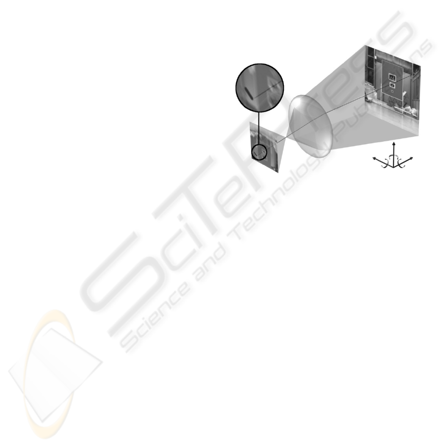
4.2 Tracing Motion Artifacts
In our approach we consider the intrinsic camera
parameters and the position and orientation of the
camera relative to the gyroscope. The direction of
the view vector varies over the image. Therefore the
effect of camera motion is different at every image
point. It is calculated by first projecting points from
image space into world space by using the camera’s
intrinsic matrix while considering its lens distortion
(See Figure 3). The camera’s depth of field could be
used as a rough clue. As discussed earlier, rotation is
the main cause of artifacts in many scenarios. Here,
solely the view vector at the considered image points
is relevant.
In a second step the measured motion is applied
successively to the virtual camera while tracing the
path in image space described by the projected point.
The quality estimate for an image point is
determined by the length of the path as well as by
the maximum distance between any of two points on
that path. We map the strength of motion artifacts to
the interval from 0.0 to 1.0, where 1.0 stands for an
immobile camera. The quality reaches 0.0 for
infinitely high motion artifact strength.
As stated above, the direction of sight rays and
thus the quality estimate varies over different image
points. To get a single estimate for the entire image,
several possibilities exist to combine the data. The
simplest method is to only consider quality at the
image center. Depending on the application, it is
also possible to sample quality values over the entire
image or from predefined areas of interest and then
use the average or the lowest quality as the overall
quality measure. When combining samples over a
larger area it is possible to account for rotation
around the optical axis, which could not be detected
when only considering the image center.
Figure 3: Basic principle of tracing motion artifacts.
5 DATA PROCESSING SCHEME
While researchers made various efforts to deal with
motion artifacts, many of them are not well suited
for mobile robot applications. Undoing blur is a slow
and cumbersome process. Adaptive triggering of
image acquisition depending on current camera
movement is a promising and computationally
inexpensive approach. However, a sudden increase
in camera movement during exposure cannot be
predicted.
In our system, we chose to continuously acquire
images as well as motion data and apply a selection
process at a later stage. One advantage is that the
actual movement of the camera during image
exposure is known for every individual image.
Another advantage is that ‘bad’ pictures are not
prevented from being acquired. A scheme for
rejecting individual frames at an early processing
stage is applied instead. Depending on the
application, blurry images may still be used if
continuous image degradation happens for a
prolonged period of time.
ICINCO 2009 - 6th International Conference on Informatics in Control, Automation and Robotics
240
5.1 Image Acceptance Test and
Congestion Control
We consider mobile platforms to have in general a
limited computing capacity. At the same time we
assume that image processing tasks consume
significant resources. Here, the frame rate of a
camera may easily exceed the image processing
capacity.
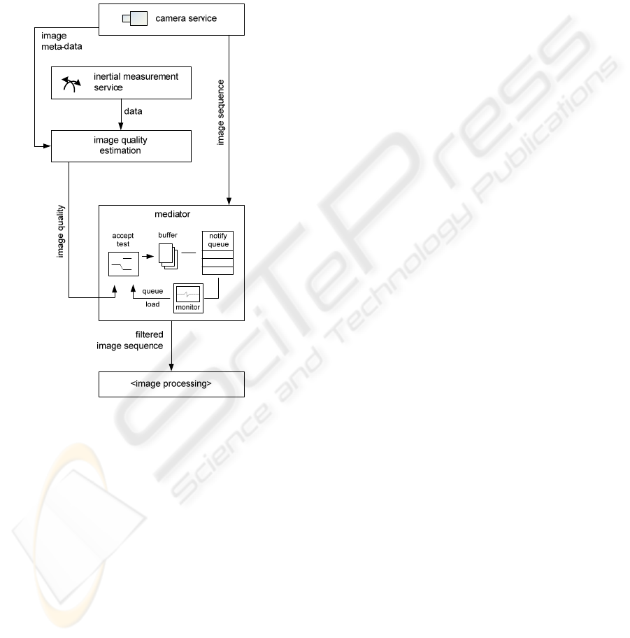
Figure 4: Structure of a system containing a mediator
service for congestion control.
As shown in Figure 4, instead of dropping
random frames, we can apply a simple, yet effective
congestion control scheme. Having a normalized
image quality value available for every frame
enables us to compare it directly to the current
system load. Images are only accepted for further
processing if their image quality is greater than the
system load indicator. This implies that in case the
system is idle, even images containing heavy motion
artifacts are accepted for further processing. This
ensures that it is not possible to reject every image
for an extended period of time. The system load
indicator is derived from the percentage of utilized
space in the image queue right before the image
processing stage mapped to the interval from 0.0 to
1.0.
5.2 Data Processing Strategies
The basic data processing scheme has been
described in the previous section. However, as in the
computation of a global quality estimate for the
entire image, some variations or extensions are also
possible at this stage.
Minimum Quality. If an application requires that
the degree of motion artifacts doesn’t exceed a
certain degree, it is possible to specify a minimum
quality value at the mediator to prevent it from
accepting low quality images.
Binning Images. Scenarios where degraded images
can still be useful if they are processed in an
alternative way compared to artifact-free images can
also be supported. Here, the mediator shown in
Figure 4 can be extended to route images with
quality estimates below a certain threshold to
another processing module. An example of such a
scenario may be a system for visual odometry where
images are too blurry to match corresponding
features in successive frames but can be used to
derive camera motion from blur instead. Another
scenario is the combination with deblurring
algorithms. To prevent starvation of image
processing in case of unacceptable blurry images for
a long period of time, it is possible to route
individual images through a deblurring stage when
the load indicator becomes low.
Reusing Quality Estimates. It may also be
desirable of course to include the quality estimate or
even the computed paths of movement at individual
image locations in later processing stages. The
overall quality measure can be easily included in the
image metadata at the mediator stage. If access to
more detailed data is required, it is more suitable to
establish an additional connection between the
quality estimation module and the processing stage
and access desired data on demand.
6 SYSTEM EVALUATION
In this section we show results achieved with our
approach to image quality estimation. We also
present improvements of a scenario where markers
are to be detected by a mobile robot while driving on
a bumpy floor.
SCHEME FOR EVALUATION AND REDUCTION OF MOTION ARTIFACTS IN MOBILE VISION SYSTEMS
241
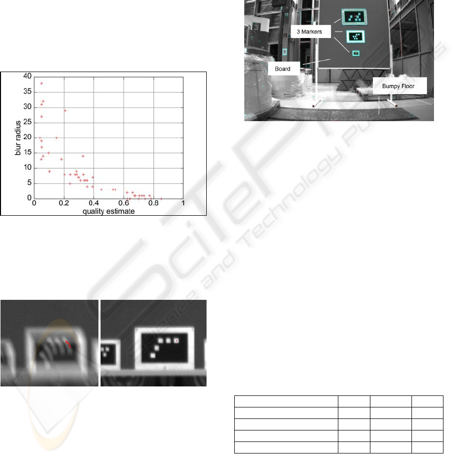
6.1 Evaluation of Motion Artifact
Detection
In a first experiment we examined the correlation
between motion blur in camera images and the
computed quality based on angular rate
measurement. A mobile robot was equipped with a
front facing camera and was driving towards a board
placed in front of it. The robot passed various bumps
of a maximum height of 1 cm, which resulted in
displacement as well as rotation of the robot. Figure
5 shows the correlation between blur radius at the
image center and computed quality values. The blur
radius was measured manually in each individual
image.
Figure 5: Correlation between quality estimate and actual
strength of motion blur.
In Figure 6 small parts of a blurry and a non-
blurry image is shown. The red dots indicate the
motion calculated using inertial data only.
Figure 6: Motion blur traced by inertial data.
6.2 Improving a Marker Detection
Scenario
We applied our approach to a scenario where optical
markers were to be recognized by a moving mobile
robot. The computing capacity onboard the robot is
limited. Therefore not all images acquired by the
onboard camera can be processed. The lights were
set to about 300 lux, which resulted in an average
integration time of 60 ms. A 2/3 inch monochrome
CCD sensor and a 4.8 mm fixed focus C-Mount lens
were used in the experiment.
The robot was approaching a board from a
distance of approximately 13 meters. Markers of
different sizes were attached to the board (See
Figure 7). The goal when approaching the board was
to recognize the markers as frequently as possible.
Figure 7: Test setup of the marker detection scenario.
Images and motion data were recorded in order
to compare results achieved with uncontrolled frame
drops due to queue overflow against results with
dynamic congestion control. The total number of
images acquired during the approach was 319. The
average processing time per frame required by the
marker detection algorithm was approximately 1.6
times the interarrival time of new images. Table 1
shows the number of images in which a marker
could be identified for one particular approach. In
general, markers could not be recognized in all 319
frames because at first they were too far away, went
partially outside of the image, or they were obscured
by motion blur. It can be seen that the improvement
in the total number of images with recognized
markers increases with the decreasing size of the
marker. This is because smaller markers are easily
obscured by blur.
Table 1: Improvements of recognition results when
applying dynamic filtering.
Marker Large Medium Small
recognizable 246 272 99
recognized(uncontrolled) 154 159 62
recognized(filtered) 161 178 71
Improvement [pct.] 4.5 11.9 14.5
ICINCO 2009 - 6th International Conference on Informatics in Control, Automation and Robotics
242

7 CONCLUSIONS
Here we presented an approach to improve the
performance of image processing tasks on mobile
robots equipped with common fixed focus, low-cost
cameras. The basic idea presented was to improve
the quality of images processed by arbitrary vision
algorithms by estimating the amount of motion
artifacts for every image and rejecting bad ones
while also considering a system load indicator.
Our system is suitable for resource-constrained
robots where the camera’s frame rate usually
exceeds the processing capabilities of the onboard
computer. Based on improvements we have seen in
an example scenario, we are confident that the
performance of a number of different image
processing tasks can be improved through this
approach.
ACKNOWLEDGEMENTS
This work has been funded in part by the German
Federal Ministry of Education and Research under
grant 01IM08002.
REFERENCES
Schiehlen, J., Dickmanns, E. D.: Design and control of a
camera platform for machine vision, In: Proc. of IEEE
Int. Conf. on Intelligent Robots and Systems ’94, pp.
2058-2063, 1994.
Yeom, D., Park, N., Jung, S.: Digital controller of novel
voice coil motor actuator for optical image stabilizer,
In: Proc. of Int. Conf. on Control, Automation and
Systems ‘07, pp. 2201-2206, 2007.
Cardani, B.: Optical image stabilization for digital
cameras, In: IEEE Control Systems Magazine vol. 26
no. 2, pp. 21-22, April 2006.
Chi-Wei Chiu, Chao, P. C. - P., Din-Yuan Wu: Optimal
Design of Magnetically Actuated Optical Image
Stabilizer Mechanism for Cameras in Mobile Phones
via Genetic Algorithm, In: IEEE Transactions on
Magnetics vol. 43 no. 6, pp. 2582-2584, June 2007.
Sato, K., Ishizuka, S., Nikami, A., Sato, M.: Control
techniques for optical image stabilizing system, In:
IEEE Transactions on Consumer Electronics vol. 39
no. 3, June 1993.
Günthner, W., Wagner, P., Ulbrich, H.: An inertially
Stabilised Vehicle Camera System. Hardware,
Algorithms, Test Drives, In: Proc. of IEEE Conf. on
Industrial Electronics ‘06, pp. 3815-3820, 2006.
Ji, H., Liu, C.: Motion blur identification from image
gradients, In: IEEE Conf. on Computer Vision and
pattern Recognition ‘08, pp. 1-8, 2008.
Fergus, R., Singh, B., Hertzmann, A., Roweis, S. T.,
Freeman, W. T.: Removing camera shake from a
single photograph, In: Proc. of ACM SIGGRAPH ’06,
pp. 787-794, 2006.
Cho, W. H., Hong, K.-S.: A fast CIS still image
stabilization method without parallax and moving
object problems, IEEE Transactions on Consumer
Electronics vol. 54 no. 2, May 2008.
Nicklin, S. P., Fisher, R. D., Middleton, R. H.: Rolling
Shutter Image Compensation, In: Lecture Notes in
Computer Science vol. 4434/2007, Springer, 2007.
Chun, J.-B., Jung, H., Kyung, C.-M.: Suppressing rolling-
shutter distortion of CMOS image sensors by motion
vector detection, IEEE Transactions on Consumer
Electronics, vol.54, no.3, 2008.
Choi, B.-D., Jung, S.-W., Ko, S.-J.: Motion-blur-free
camera system splitting exposure time, IEEE
Transactions on Consumer Electronics, vol.54, no.3,
2008.
SCHEME FOR EVALUATION AND REDUCTION OF MOTION ARTIFACTS IN MOBILE VISION SYSTEMS
243
