
STRAIN FIELD INTERPOLATION OVER THE SCIARA DEL
FUOCO (STROMBOLI VOLCANO) FROM GEODETIC
MEASUREMENTS ACQUIRED BY THE AUTOMATIC THEODOROS
SYSTEM
Giuseppe Nunnari, Alessandro Spata
Dipartimento di Ingegneria Elettrica, Elettronica e dei Sistemi, Universit´a degli Studi di Catania
Viale A. Doria 6, 95125 Catania, Italy
G
iuseppe Puglisi, Alessandro Bonforte, Francesco Guglielmino
Istituto Nazionale di Geofisica e Vulcanologia, sezione di Catania, Piazza Roma 2, 95125 Catania, Italy
Keywords:
Automatic monitoring system, Data-processing, Strain interpolation, Stromboli volcano.
Abstract:
In this paper we treat two important aspects concerning the automatic monitoring of the ground deformation
at the Sciara del Fuoco (SdF), the Stromboli volcano (Italy) steep flank subjects to dangerous landslide events:
the developments of suitable software procedures to process observations and the evaluation of both 3D motion
maps and 3D strain tensor over the whole investigated area. Ground deformation measured by the monitoring
system known as THEODOROS (THEOdolite and Distancemeter Robot Observatory of Stromboli) is often
affected by offsets and spikes, due to both malfunctioning and periodical maintenances of the system, and other
noise sources making very difficult the interpretation of the ground deformation dynamics. To this purpose a
suitable software tool able to reduce these drawbacks was developed. Furthermore, both 3D motion maps and
3D strain tensor are computed in order to provide new useful information aimed to better understanding the
complex dynamic of the SdF.
1 INTRODUCTION
Stromboli is an active volcano, about 2500 m high
above the sea floor. Roughly only the last kilometre of
this volcano emerges from the sea, forming an island
whose diameter ranges from 2.4 to 5 km. It belongs
to the Aeolian Islands and represents the most active
volcano of this archipelago. Its conic shape is evi-
dently characterized by a big depression that marks
the northwestern flank of the edifice: the Sciara del
Fuoco (SdF). On December 28th, 2002, lava flows
outpoured from the northern wall of the NE crater and
descended into the Sciara del Fuoco, a deep depres-
sion marking the NW flank of the volcano edifice.
On December 30th, 2002, two landslides occurred
on the northern part of the Sciara del Fuoco; they
moved a mass in the order of tens of millions of cu-
bic meters both above and below sea level. The land-
slide produced a tsunami causing significant damage
to the eastern coast of the island, reaching the other
Aeolian Islands and the Sicilian and southern Italian
coasts. This event led to the upgrading of the ground
deformation monitoring system, already existing on
the island; the new requirement was the real-time de-
tection of the deformations related to potential slope
failures of the SdF. To this purpose the chosen in-
strument was the Leica TCA 2003 Total Station (TS)
equipped with GeoMos software ((Leica, 2002) that
allows remote sensor control. The acronym of this
system is THEODOROS (THEOdolite and Distance-
meter Robot Observatory of Stromboli) (Puglisi et al.,
2004). The rest of this paper is organized in the fol-
lowing way. In Sec. II a brief description of the cur-
rent THEODOROS configuration is given, the inter-
ested reader can found more detailed information and
a general map of the island with the position of the
reflectors in (Puglisi et al., 2004) and (Nunnari et al.,
2008). Sec. III reports the approach adopted to pre-
processing data; Sec. IV shows the methodology used
to compute the strain field; Sec. V reports the case
study; finally Sec. VI draws the conclusions of this
study.
28
Nunnari G., Spata A., Puglisi G., Bonforte A. and Guglielmino F. (2009).
STRAIN FIELD INTERPOLATION OVER THE SCIARA DEL FUOCO (STROMBOLI VOLCANO) FROM GEODETIC MEASUREMENTS ACQUIRED BY
THE AUTOMATIC THEODOROS SYSTEM.
In Proceedings of the 6th International Conference on Informatics in Control, Automation and Robotics - Signal Processing, Systems Modeling and
Control, pages 28-32
DOI: 10.5220/0002210000280032
Copyright
c
SciTePress
2 BRIEF INTRODUCTION TO
THE THEODOROS SYSTEM
The THEODOROS system consists of a remote-
controlled Total Station that can be programmed to
measure slope distances and angles between the sen-
sor and benchmarks appropriately installed in the
SDF area at a specific sampling rate. To ensure a
continuous stream of data from the instrument, it re-
quires a constant power supply and a continuous link
with the PC controlling the Total Station’s activities,
installed on the S. Vincenzo Observatory, where the
National Department of Civil Protection (DPC) con-
trol room is located. The Stromboli volcano eruption
of the 27 February 2007 destroyed the THEODOROS
benchmarks inside the SDF. A new configuration was
designed and new benchmarks were installed on the
new fan produced by the lava flow entering the sea.
This new topology consists of six reflectors installed
outside the SdF, around the Total Station, for the ref-
erence system and atmospheric corrections (SENT,
BORD, SEMF, SPLB2, CIST and ELIS), nine reflec-
tors for monitoring movements of the lava fan inside
the SdF (SDF18, SDF19, SDF20, SDF21, SDF22,
SDF23, SDF24, SDF25 and SDF26), two reflectors
to monitor the northern border of the SdF (400 and
BASTI) and two further reflectors on stable sites to
check the stability of the measurements both on short
and very long distance measurements (CURV and
CRV). Currently the reflectors SDF20 and SDF21 are
not working. The sample time indicated as t
c
here-
after is set to be t
c
= 10 minutes. Each measure-
ment for each target or reference point provides the
instantaneous values of three relevant pieces of infor-
mation: the slope distance (sd), the horizontal (hz)
angle and the vertical angle (ve). Starting from this
information, the GeoMos system is able to transform
the TS measurement vectors (whose components are
sd, hz, ve) into an equivalent vector whose compo-
nents are expressed in terms of North (N), South (S)
and Up (U) with respect to the assumed reference sys-
tem. In this computation, GeoMos is able to take into
account the constraints imposed by the assumption
of the reference system. Despite the availability of
real-time information, this is not enough to automat-
ically evaluate the state of ground deformation. In-
deed the acquired measures are affected by offsets,
spikes and noise sources that strongly compromised
their interpretation. These drawbacks must be neces-
sary overcome before that suitable quantities related
to the ground deformation dynamic can be efficiently
computed. In particular in this paper we focus our at-
tention on the problems of offsets and spikes removal,
smoothing noisy data and strain tensor evaluation.
3 PRE-PROCESSING DATA
The algorithm we propose to remove both spikes and
offsets consists of two steps. First the spikes are re-
moved, then attention is focused on offsets. Since the
single displacement components (North, East, Up) of
each benchmark in the period June 2006 - Decem-
ber 2008 are characterized by a normal distribution,
the problem to remove the spikes affecting observa-
tions, i.e. the sharp variations of the time series which
are generally due to either periodical maintenance
or instrument malfunctions, is well solved adopting
the standard deviation of observations as reference.
Indeed let T
SDF
x
(t) be a generic component of the
benchmark SDF
x
at time t, let ∆T
SDF
x
(t) be the dif-
ference between two subsequent measures and denot-
ing as σ its standard deviation, the experience gained
through the daily monitoring of the SdF suggest us to
consider as spikes the ∆T
SDF
x
(t) values falling outside
the range covered by one σ.
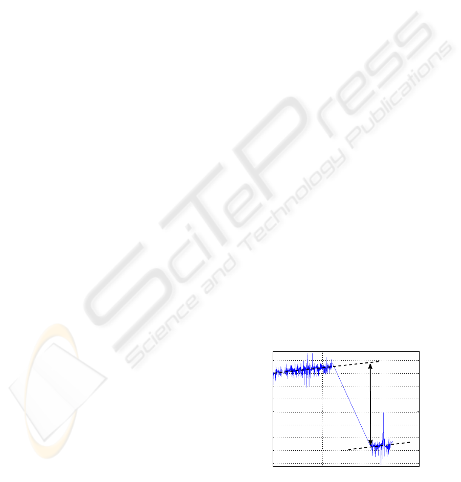
The offsets affecting observations are essentially
due to the maintenances of the THEODORO system.
Here it is necessary to distinguish two types of main-
tenances: periodical maintenance usually carried out
every six months, and extra maintenance due to un-
expected crash of the system. The offsets related to
the periodical maintenance are simply adjusted taking
into account the marked sharp variation (jump) visi-
ble when the system begins to work. This approach is
also suitable for offset due to the crash of the system if
the normal functioning of the system is promptly re-
stored. Instead, if the extra maintenance is performed
after a sufficiently long time the system crashed, then
the offsets removal is not trivial. Indeed, in this case,
in order to perform a reliable offsets correction the
estimation of the trend of each ground deformation
component during the period in which the system was
crashed is needed. In order to adjust these kinds of
offsets we use the linear trend as shown in figure 2.
01/01/09
280
300
320
340
360
380
400
420
440
Time
Displacement (mm)
Figure 1: Offsets correction approach based on linear trend.
Although both spikes and offsets removal makes
STRAIN FIELD INTERPOLATION OVER THE SCIARA DEL FUOCO (STROMBOLI VOLCANO) FROM
GEODETIC MEASUREMENTS ACQUIRED BY THE AUTOMATIC THEODOROS SYSTEM
29
ground deformations more readable, further process-
ing is needed to reduce noise source affecting data,
in particular the thermoelastic effects on ground de-
formation due to the temperature. To this purpose we
have smoothed noisy data with spline functions fol-
lowing the suggestion of the literature (Biloti et al.,
2008), (Ge et al., 2003). A spline function s(t) is
a function defined piecewise by polynomials. This
function takes values from an interval [a, b] and maps
them to R, the set of real numbers. The interval [a, b]
is divided into k disjoint subintervals [t
i
, t
i+1
] with
0 ≤ i ≤ k− 1 such that [a, b] = [t
0
, t
1
]U...U[t
k−2
, t
k−1
].
The given k points t
i
are called knots. The vector
t = (t
0
, .., t
k−1
) is called a knot vector for the spline.
If the knots are equidistantly distributed in the inter-
val [a, b] the spline is uniform, otherwise it is non-
uniform. On each of this subintervals a nth polyno-
mial is defined and joined with others polynomials at
the knot points in such a way that all derivatives up
to the (n− 1)th degree are continuous. Within these
constraints, the function s(t) is selected which mini-
mizes:
∑
(s(t
i
) − x
i
)
2
+ p
Z
(s
(
n+1
2
)
(t))
2
dt (1)
where (t
i
, x
i
) are the raw data samples and s(k) de-
notes the kth derivative of s(t). The weight factor p
is the smoothing parameter whose value must be op-
portunely chosen to obtain a good compromise be-
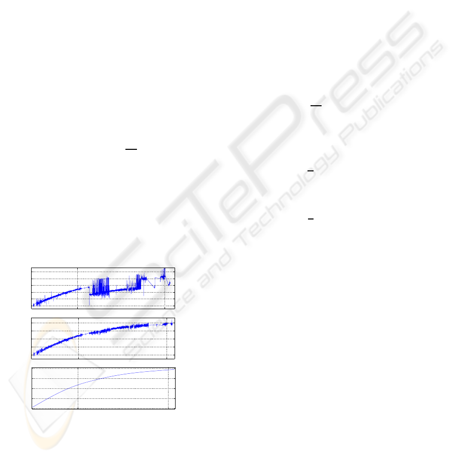
tween good fit and the smoothness. In figure 2 are
shown, respectively, the raw data of the benchmark
SdF26 (North component), the data after removing
spikes and offsets and finally the spline-smoothing.
01/01/08 01/01/09
0
100
200
300
400
500
displacement (mm)
01/01/08 01/01/09
0
100
200
300
400
displacement (mm)
01/01/08 01/01/09
0
100
200
300
400
displacement (mm)
(a)
(b)
(c)
Figure 2: (a) Original SDF26 North component; (b) Spikes
and offset removed; (c) Smoothing noise.
4 STRAIN INTERPOLATION
In order to compute both 3D displacements map
and strain tensor in the area of SdF covered by the
THEODOROS system we use the modified least-
square approach introduced by (Shen et al., 1996)
and also used by (Pesci and Teza, 2007) and (Teza
et al., 2008). Given a point P having position
x0 = (x
10
, x
20
, x
30
) surrounded by N experimental
points (EPs) whose positions and displacements are
respectively x(n) = (x
1(n)
, x
2(n)
, x
3(n)
) and u(n) =
(u
1(n)
, u
2(n)
, u
3(n)
) where n = 1..N, the problem of es-
timating both the displacements gradient tensor H and
the displacement componentsU
i
(i = 1..3) of the point
P, according to the infinitesimal strain theory, can be
modelled in terms of the followingstrain interpolation
equations:
u
i(n)
(x) = H
ij
∆x
j(n)
+U
i
(i, j = 1..3) (2)
where ∆x
j(n)
= x
j(n)
− x
j0
are the relative positions
of the nth EP experimental points and the arbitrary
point P and H
ij
=
∂u
i
∂x
j
are the elements of the dis-
placement gradient tensor. It can be decomposed in a
symmetric and an anti-symmetric part as H = E + Ω,
where E is the strain tensor defined as:
E =
1
2
(H
ij
+ H
ji
)e
i
⊕ e
j
(3)
and Ω is the rigid body rotation tensor defined as:
Ω =
1
2
(H
ij
− H
ji
)e
i
⊕ e
j
(4)
Here e
i
is the base vector of the Cartesian ref-
erence system and ⊕ is the tensor product. In
a compact form the undetermined system of equa-
tions (2) can be written as Al = u where A is
the design matrix simply derivable from equation
(2), l = [U
1
U
2
U
3
ε
11
ε
12
ε
13
ε
22
ε
23
ε
33
ω
1
ω
2
ω
3
]
is the vector of unknown parameters and u =
[u(1) u(2) u(n)]
T
is the observation vector. Assum-
ing a uniform strain field and re-writing the previous
linear equation (4) as Al = u+ e, where e is the resid-
ual vector which model the stochastic nature of the
estimation problem, a suitable method to solve the
system is the Weighted Least Squares (WLS) which
gives the expression (5) as a suitable formula to esti-
mate the unknown vector l
ˆ
l = (A
T
WA)
−1
A
T
Wu (5)
In (5) W is the data covariance matrix. Usually W
is assumed to be diagonal (uncorrelated data), i.e. of
the form
W = diag(σ
−2
1(1)
, σ
−2
2(1)
, σ
−2
3(1)
, ..., σ
−2
1(n)
, σ
−2
2(n)
, σ
−2
3(n)
)
(6)
ICINCO 2009 - 6th International Conference on Informatics in Control, Automation and Robotics
30
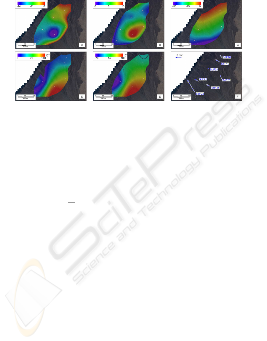
Figure 3: In the frames (a), (b), and (c) are reported the calculated East, North and Up components of displacements respec-
tively. Frames (d) and (e) report the maximum shear strain and the volume variation. Finally, in the frame (f) the displacement
vectors of the benchmarks are shown.
where the quantities σ
j(n)
’s are the standard devia-
tions of the measurements. According to the modi-
fied least squares (MLS) approach proposed by (Shen
et al., 1996), based on the adjustment of the covari-
ance matrix W, we use the matrix W
′
which is a
weighted version of the matrix W of experimental
data. Following the suggestion given by (Shen et al.,
1996) and (Teza et al., 2008) the weight function con-
sidered here is:
W
′
= We
−
d
(n)
d
0
(7)
where d
(n)
is the distance between the nth EP and the
arbitrary point P, and d
0
is a distance-decaying con-
stant defining the ”level of locality” of the estimation.
This method, likewise most previous methods
(Frank, 1966) and (Prescott, 1976) is used to inter-
polate the strain among benchmarks of geodetic net-
works where ground deformations are measured by
comparing geodetic surveys.
5 AN APPLICATION TO THE
SCIARA DEL FUOCO
The benchmarks placed on the lava fan show a gen-
eral NW-ward motion following the maximum slope
of the SdF, with an increasing magnitude from NE
to SW (Fig. 3f). This kind of deformation is in
good agreement with a seawards motion of the new
lava fan, driven by a mainly gravitational dynamics.
However, the ground motion is not uniform above the
investigated area, showing significant differences in
the displacements measured on different benchmarks.
In order to analyze the ground deformation pattern
recorded from December 14, 2008 to January 3, 2009
above the deforming lava body, we performed a strain
interpolation. Unfortunatly the corresponding lin-
ear system is undetermined since it implies more un-
knows (n = 9) that equations (m = 7). Therefore the
solution is never unique. To this reason we have cal-
culated a basic solution with almost m non zero com-
ponents by using the QR factorization with column
pivoting. Results are reported in Fig. 3, where the
decrease of the horizontal motion (Fig. 3a and b) is
evident from benchmark SDF25, that is located on the
upper and central area of the fan, towards the coast-
line and towards North, reaching the minimum values
at SDF18 benchmark, located close to the SdF north-
ern rim. The vertical motion (Fig. 3c) shows a more
uniform gradient, from a maximum down-lift of about
50 mm at the S-Westernmost benchmark (SDF22) to
near 0 at SDF18. A deeper analysis of the overall
deformation of the lava fan is allowed by the interpo-
lation of the strain tensor. In Fig. 3d, the distribu-
tion of the maximum 3D shear strain is reported, con-
firming the strongest deformation on the upper area of
the lava fan; this is mainly due to the stronger magni-
tude of horizontal displacements of the southernmost
SDF22, SDF25 and SDF26 benchmarks with respect
to the northern half of the fan, but also to the relative
vertical motion of the two halves of the body. On the
upper area, also the volumetric dilatation evidences
a maximum expansion (Fig. 3e), mainly imputable
to the divergent directions of the displacements af-
fecting SDF25 and SDF26 benchmarks. In addition,
a contracting area is detected on the southern coast-
line of the fan, due to the smaller displacements of
the SDF23 and SDF24 benchmarks with respect to
the upper ones, while all the northern half of the lava
body shows no significant volumetric strain variation
STRAIN FIELD INTERPOLATION OVER THE SCIARA DEL FUOCO (STROMBOLI VOLCANO) FROM
GEODETIC MEASUREMENTS ACQUIRED BY THE AUTOMATIC THEODOROS SYSTEM
31

confirming the higher stability of this portion of the
fan that is buttressed by the stable northern wall of
the SdF.
6 CONCLUSIONS
In this paper we have first shown the pre-processing
techniques adopted to reduce noise sources affecting
ground deformation measures acquired at the Sciara
del Fuoco by the automatic monitoring system re-
ferred to as THEODOROS. In particular, due to the
gaussian distribution of acquisitions, the problem of
spikes removal was simply solved taking into account
their standard deviations. The offsets due to the crash
of the system have been adjusted based on the evalua-
tion of the linear trend of observations. Finally spline
functions have been used to reduce the thermoelas-
tic effects. After these pre-processing steps we have
shown the based on infinitesimal strain theory method
used to compute both displacements maps and strain
field over the area covered by the THEODOROS sys-
tem. Finally a case study related to the ground mo-
tion observed in the period December 2008 - January
2009 was carried out in order to test the proposed
methodology. Preliminary results show that the dis-
tribution of the maximum 3D shear strain emphasizes
the strongest deformation on the upper area of the lava
fan. Furthermore the volume variation highlights a
contracting area on the southern coastline of the fan.
Finally all the northern half of the lava body shows
no significant volumetric strain variation confirming
the higher stability of this portion of the fan that is
buttressed by the stable northern wall of the SdF.
REFERENCES
Biloti, R., Santos, L. T., and Martin, T. (2008). Auto-
matic smoothing by optimal splines. Rev. Bras. Geof,
21(2):173–177.
Frank, F. C. (1966). Deduction of earth strains from survey
data. Bull. Seismol. Soc. Am., 56(1):35–42.
Ge, L., Chang, H. C., Janssen, V., and Rizos, C. (2003).
The integration of gps, radar interferometry and gis
for ground deformation monitoring. In TInt. Symp. on
GPS/GNSS. UTAS.
Leica (2002). Software geomos user manual. LEICA and
GEODETICS Inc.
Nunnari, G., Puglisi, G., and Spata, A. (2008). A warn-
ing system for stromboli volcano based on statistical
analysis. PAGEOPH, 165(8):1619–1641.
Pesci, A. and Teza, G. (2007). Strain rate analysis over the
central apennines from GPS velocities: the develop-
ment of a new free software. Bollettino di Geodesia e
Scienze Affini, 56:69–88.
Prescott, W. H. (1976). An extension of franks method for
obtaining crustal shear strains from survey data. Bull.
Seismol. Soc. Am., 66(6):1847–1853.
Puglisi, G., Bonaccorso, A., Mattia, M., Aloisi, M.,
Bonforte, A., Campisi, O., Cantarero, M., Falzone,
G., Puglisi, B., and Rossi, M. (2004). New inte-
grated geodetic monitoring system at stromboli vol-
cano (italy). Engineering Geology, 79(1-2):13–31.
Shen, Z. K., D., D., and Ge, B. X. (1996). Crustal defor-
mation across and beyond the los angeles basin from
geodetic measurements. Journal of Geophysical Re-
search, 101(27):957980.
Teza, G., Pesci, A., and Galgaro, A. (2008). Gridstrain and
Gridstrain3 : Software packages for strain field com-
putation in 2D and 3D environments. Computers and
Geosciences, 34(9):1142–1153.
ICINCO 2009 - 6th International Conference on Informatics in Control, Automation and Robotics
32
