
SELF-LOCALIZATION OF A TEAM OF MOBILE ROBOTS BY
MEANS OF COMMON COLORED TARGETS
Patricio Nebot and Enric Cervera
Department of Computer Science and Engineering, Jaume-I University, Campus de Riu Sec, Castell´on de la Plana, Spain
Keywords:
Mobile robots, Visual localization, Color vision, Common objects.
Abstract:
Robot localization is one of the fundamental problems in mobile robotics. Using sensory information to
localize the robot in its environment is the most fundamental problem that has to be solved in order to provide
a mobile robot with autonomous capabilities, But, if robots can detect each other, there is the opportunity to
do better. In this paper, it is explained how one robot, the leader, with a pan-tilt-zoom camera mounted on
it can localize a team of robots. Camera images are used to detect other robots and to determine the relative
position of the detected robot and its orientation with respect to the leader. Each robot carries a colored target
that helps the leader to recognize it and calculate their position and orientation. Moreover, the zoom is used to
enhance the perception and get a higher accuracy and a larger field of view.
1 INTRODUCTION
Cooperation among a group of robots has been a topic
of very much study during the last years. To have a
cooperative system it is necessary for more than one
organism to have a relationship with another or anoth-
ers. So, to implement cooperation in a robotic system,
it is necessary to have more than one robot working in
the same environment, that is, a multirobot system.
There are several applications in which having
more than one robot working in parallel has improved
the system’s fault tolerance, and has reduced the time
required for executing the tasks. Some of these appli-
cations are autonomous cleaning, tour guiding in mu-
seums, art-galleries, or exhibitions, surveillance and
patrolling, rescue in disasters such as fires, floods,
earthquakes, landmine detection and autonomous ex-
ploration and mapping.
In more of these applications it is necessary the
use of vision in order to implement or acomplish the
tasks. Human and animal vision are the most power-
ful perception systems. Vision is a sense that consists
of the ability to detect the light and interpret it, that
is “see”. Vision gets help from multiple information
sources to interpret the world. The visual system al-
lows to assimilate information from the environment
to help guide the actions.
One of the most important task in computer vision
is recognition, which consists of determining whether
or not the image data contains some specific object,
feature, or activity. One of the most characteristic task
in recognition is “pose estimation”, that estimates the
position or orientation of a specific object relative to
the camera.
In this paper, a similar task is implemented. In
this case, one robot with a camera tries to estimate the
pose of the rest of robot of the team, which don’t have
a camera available. In that way, the robot with the
camera can help the rest of robots in case of lost of
their possitions due to inaccurate odometric estima-
tion pose.
To determine the relative location of other robots,
the leader uses the visual information obtained from
the pan-tilt-zoom on-board camera. Camera images
are used to detect other robots and to determine the
relative position of the detected robot and its orien-
tation with respect to the leader. Each robot carries
a colored target that helps the leader to recognize it
and calculate their position and orientation. More-
over, the zoom is used to enhance the perception and
get a higher accuracy and a larger field of view.
Robot localization has been recognized as one of
the fundamental problems in mobile robotics (Fox
et al., 2000). Using sensory information to localize
the robot in its environment is the most fundamental
problem that has to be solved in order to provide a
mobile robot with autonomous capabilities (Cox and
Wilfong, 1990). Most of the existing work in localiza-
tion is addressed to the localization of a single robot
by itself. However, if robots can detect each other,
274
Nebot P. and Cervera E. (2009).
SELF-LOCALIZATION OF A TEAM OF MOBILE ROBOTS BY MEANS OF COMMON COLORED TARGETS.
In Proceedings of the 6th International Conference on Informatics in Control, Automation and Robotics - Robotics and Automation, pages 274-279
DOI: 10.5220/0002212402740279
Copyright
c
SciTePress

there is the opportunity to do better. When a robot
determines the location of another robot relative to
its own, both robots can improve the accuracy with
which they localize each other.
Vision has been widely used to get exteroceptive
information in order to detect and localize robots. Al-
though omnidirectional cameras have been used in
the detection and localization of robots (Das et al.,
2002), directional cameras suppose a better option
due to their much lower cost (Sarcinelli-Filho et al.,
2003) and because they have complementary perfor-
mances despite the visibility constraints (Michaud
et al., 2002). Regarding the image processing, color
has been widely used to achieve robot detection
(Fredslund and Mataric, 2002; Michaud et al., 2002).
However, the robustness of color detection with re-
spect to light conditions can be a major source of fail-
ures (Cubber et al., 2003).
Also, the use of the zoom has been used in the
context active vision (Atienza and Zelinsky, 2001) or
visual servoing (Hosoda et al., 1995). For using the
zoom, it is necessary the explicit knowledge of in-
trinsic parameters from the calibration of the camera
(Clady et al., 2001).
The rest of the paper is organized as follows.
Section 2 provides a description of the experimental
setup. Section 3 explains the process to lozalize the
different robots of the team. Finally, section 4 pro-
vides some general conclusions and lines of future
work.
2 EXPERIMENTAL SETUP
• Hardware Setup
The team for this application consists of a group
of four Pioneer-2 mobile robots. These robots,
though sharing the same platform, have different
features, such as different accessories mounted
on them, constituting therefore a heterogeneous
group. In particular, only one robot is equipped
with a camera and the rest of robots do not have
any type of exteroceptive sensors. The robot with
the camera is in charge of detecting the rest of the
robots in the environment and indicates to them
which is their current position in the environment.
• Software Setup
The formation control is developed in Acromovi
(Nebot and Cervera, 2005), a framework specially
designed for the development of distributed ap-
plications for a team of heterogeneous mobile
robots. The software architecture gives us the
ease of development of cooperative tasks among
robots, using an agent-based platform. In particu-
lar, communication between robots can be easily
integrated to the control scheme.
3 LOCALIZATION OF THE
ROBOTS IN THE
ENVIRONMENT
This section describes how the robots can be local-
ized. Having the robots distributed in an environment,
the robot with the camera, from this point the leader,
uses the camera that it carries to detect and localize
the rest of the robots of the team and indicates to them
which is their current. This process is explained be-
low in more detail.
The first step is the detection of the robots in the
environment, in order for this decision to be taken,
the leader uses its camera to detect a series of color
patterns which identify each one of the robots in an
unequivocal way. To detect the colors, the Mezzanine
program is used.
Mezzanine (Howard, 2002) is an 2D visual track-
ing package intended primarily for use as a mobile
robot metrology system. It uses a camera to track ob-
jects marked with color-coded fiducials and infers the
pose of these objects in world coordinates. Mezzanine
works with most color cameras and can correct for the
barrel distortion produced by wide-angle lenses.
Mezzanine is used only for the detection of the
colors of the patterns that are used to recognize the
robots. And with the information that is collected
from the mezzanine system, it is possible to localize
the robots in the environment and calculate their pose
(position and orientation) with respect to the leader.
The color pattern that the leader has to search for
is created with very common object, a beer can of half
a liter covered with colored cards in a specific layout,
because each ID is unique. In figure 1, it is possible
to see the sizes and dimensions of the target and the
color layout at the front and at the back.
As it can be seen in the ID, there are two different
parts separated by a black zone. These two parts are
formed with the same colors and the same cards, but
there is a 90
o
difference in orientation between the
ID cards which means that thay are read as different
cards. That is in this way to get two different readings
of the orientation of the can and thus getting more
accurate estimations.
Since each robot carries a different color target,
the leader is able to recognise each one. Also, with
this pattern it is possible to calculate the pose of the
robot in relation to the leader. It is easy to recognize
which robot the camera is seeing, it is simply neces-
SELF-LOCALIZATION OF A TEAM OF MOBILE ROBOTS BY MEANS OF COMMON COLORED TARGETS
275
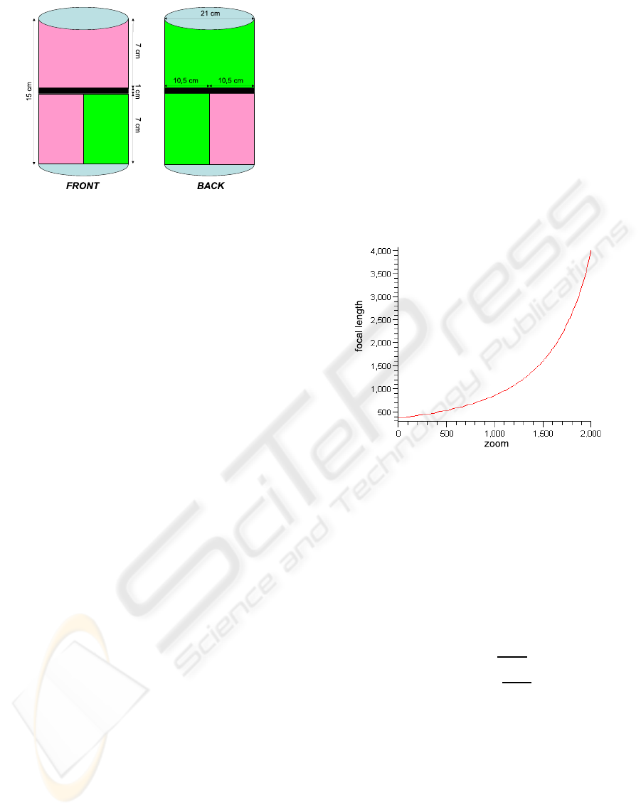
Figure 1: Dimensions and color layout of the IDs.
sary to pay attention to the layout of the colors. Mez-
zanine can detect several colors at the same time and
group the different areas of the same color in blobs.
With the information associated with these blobs it is
possible to know which ID the camera is seeing at that
moment.
The movement that the camera performs to find
these IDs is firstly horizontal movement of 180
o
from
left to right. If nothing is found in this movement,
the camera increases its vertical position in 5
o
up to a
maximum of 30
o
. If when this process has finished,
still any robot has not been identified, the leader exe-
cutes a 180
o
turn and repeats the same process until all
the robots are found. In this way, the leader searches
all the space around it for the other robots.
Throughout the searching process, mezzanine is
monitoring all their channels where it has assigned
a predefined color, and in the moment that it finds
anyone of them, the camera is stopped. From this
moment, a centering process begins. This new pro-
cess tries to center the pattern found in the middle of
the image. To this end, because the robots can be in
movement, it is important to center the target in a min-
imum number of movements, and at the same time it
is important to maximize the zoom of the camera to
make a better identification in the following phases.
In order to center the target, when mezzanine de-
tects one blob of any color bigger than a certain size,
the robot stops the searching process previously de-
scribed. The size has to be big enough to rule out
possible errors of the program or reflections of the tar-
get. From this blob it is possible to know the position
of its mass center in the image system, so the space
between this and the center of the image can be cal-
culated.
To translate this distance into a movement of the
camera, it is necessary to know some intrinsic param-
eters of the camera, such as the focal length. These
parameters can be obtained with a previous calibra-
tion of the camera.
As the camera includes a zoom, the focal length
must be calculated for each of these values of the
zoom. After several tests performed in the laboratory
by an student, Vincent Robin, during a stay there, he
managed to model the behaviour of the focal length
depending on the zoom. The function that models
these behaviours can be defined as:
f
v
= (0.0368323−0.0000128323∗z)
−2
∗1/2 (1)
being z the value of the zoom that is desired. This
function can be visualized in figure 2, and as it can
be seen, the focal length does not follow a linear pro-
gression with the progression of the zoom.
Figure 2: Relation among the necessary parameters to cal-
culate the distance to the ID.
Knowing the value of the focal length for the ac-
tual zoom of the camera, it is simple to calculate the
movements that the camera must perform in order to
center the blob in the image. There are two move-
ments that have to be made, in the pan (∇p), that is,
in horizontal, and in the tilt or vertical (∇t). These
values can be calculated as:
∇p = arctan
(x−x
i
)
f
∇t = −arctan
(y−y
i
)
f
(2)
where x and y correspond to the coordinates of the
mass center of the blob in the image, and x
i
and y
i
cor-
respond to the center of the image. With these values
the first blob that the robot finds can be centered.
Once the first blob of the target is centered, it is
possible to calculate the optimal value of the zoom in
order to reduce the detection failures of the targets of
the robots and making sure of a better approximation
in the calculation of the position of the robot. These
calculations are based on the previous work of Pierre
Renaud (Renaud et al., 2004) during a stay in this lab-
oratory.
ICINCO 2009 - 6th International Conference on Informatics in Control, Automation and Robotics
276
Prior to calculating the optimal zoom, it is nec-
essary to calculate the optimal focal length, and with
this value is possible to calculate the optimal zoom. In
order to calculate the optimal focal length, it is neces-
sary to know the actual distance (Z) to the target.
Z = f
v
∗
h
∆v
(3)
With this distance, and knowing which is the de-
sired height (h
des
) of the blob that the program needs
to get the optimal configuration, and knowing the
height of the blob in the image, the optical focal
length can be calculated.
f
op
= h
des
∗
Z
h
(4)
Finally, as deduced by Renaud in his work, the
optimal zoom can be calculated merely by knowing
the optimal focal length.
z
op
= 77928.35∗
3.6833e
−2
−(2∗ f
op
)
−0.5
(5)
Once this calculation is made, the zoom is applied
to the camera, and as the rest of the blobs or colors of
the target are now visible, it is possible to identify the
robot. This process is simple and merely perceiving
the distribution of the different colors in the target, the
different robots can be identified.
Next, in order to make the calculation of the posi-
tion more precise, a new centering process is carried
out, but this time taking into account the blobs of the
other colors present in the image. The biggest blob of
the other color in the image provides the system with
enough information to center the target in the image.
The new equations to calculate the movements of the
camera to center the target are:
∇p = arctan
((x
1
+x
2
/2)−x
i
)
f
∇t = arctan
((y
1
+y
2
/2)−y
i
)
f
(6)
Once the ID is centered on the image and with the
maximum size possible, its position and orientation
with respect to the camera, or the leader, can be cal-
culated. To know its pose (x,y,angle), it is necessary
to perform some calculations with the image.
In order to calculate (x,y), the system needs to
know the distance and the angle of the ID with re-
spect to the leader, and from these values, calculates
the position.
To calculate the distance from the ID to the im-
age, it is necessary firstly to know some parameters.
These parameters are the real height of the ID (h), the
height in pixels of the ID in the image (∇h), and the
focal length of the camera (f
v
). With these values, the
distance to the ID (Z) can be calculated as:
Z = f
v
h
∆v
(7)
The height of the ID is fixed, and the height in
pixels of the ID in the image can be obtained from the
blob information from mezzanine. The focal length
of the camera can be obtained as explained before,
merely by knowing which is the actual value for the
zoom of the camera.
The precision of the approximated distance de-
pends on the capacity of the system to recognize the
specific colors of the cylinders, which is influenced
by the prevailing lighting conditions. When the cylin-
der is lit from the side, their colors are preceived no
longer uniform, making only part of the width of the
cylinders visible to the leader. For an optimal approx-
imation, good uniform lighting is necessary.
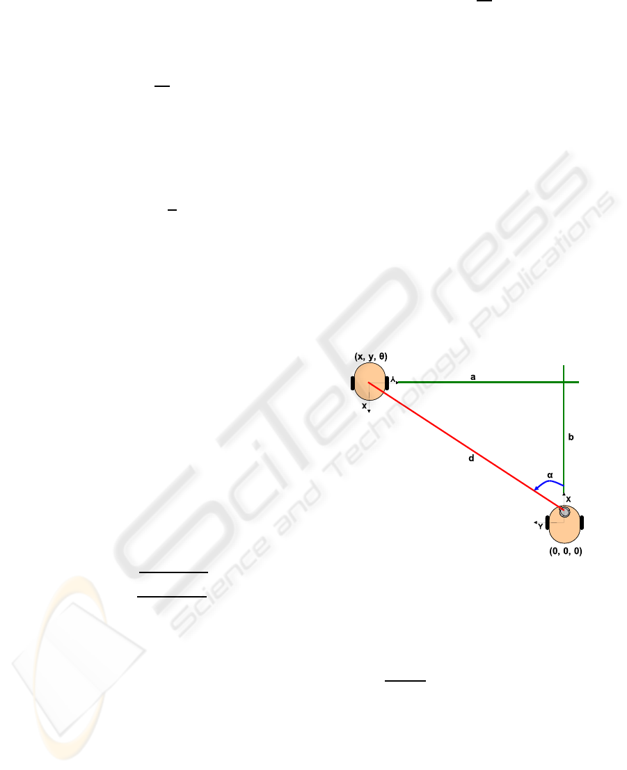
The calculation of the orientation (α) at which the
robot is depending on the leader is easier, since the
camera indicates the orientation that it has (α) at that
moment. In figure 3, the relation between orienta-
tion and distance for the calculation of the ID position
(x,y) can be observed.
Figure 3: Relation among orientation and distance with the
calculation of the ID position.
When the distance and the orientation have been
calculated, it is possible to calculate the position (x,y)
as:
d =
√
a
2
+ b
2
x = b = d ·sinα
=⇒
α = arctanb/a y = a = d ·cosα
(8)
Once the position has been calculated, it only re-
mains to calculate the orientation of the robot with
respect to the leader. For this calculation, the two hor-
izontal parts or colors of the ID are used, or rather, the
relation between these two parts.
Based on the existing relation between the hori-
zontal sizes of the two colored parts, the orientation
SELF-LOCALIZATION OF A TEAM OF MOBILE ROBOTS BY MEANS OF COMMON COLORED TARGETS
277
of the robot can be calculated. It can be observed that
the upper layer and the lower layer have the same col-
ors, but the lower layer has them with a specific turn
in relation with the configuration of the upper layer.
This is done to have two differentiated parts and to
calculate the orientation of the upper and lower layer
separately, and thus, making the calculation more pre-
cise. Moreover, as it will be seen below, in that way it
is possible to avoid some positions that are not accu-
rate enough in the calculation of the orientation.
In the calculation of the orientation using the tar-
get selected, it is very important to take into account
the order of the colors. Regarding this, from the 0
o
position of the can to 180
o
position, the pink color is
in the upper left position and grows until covers the
complete side of the can. If the green color is in the
upper left, the orientation will be from −180
o
to 0
o
,
depending on the portion of the can occupied by this
color. In the two cases, it corresponds the 90
o
or −90
o
when the two colors occupy the same portion of the
can, but depending on the color in the upper left side,
the orientation will be positive or negative.
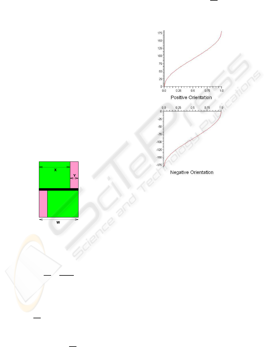
From the relation of the left part (X) and right part
(Y), the orientation of the robot can be calculated. The
relation among the left and right parts and the entire
width of the cylinder can be seen in figure 4.
Figure 4: Relation among the parts to calculate the orienta-
tion of the robot.
From the figure, it can be deducted when the left
and right parts are equal that
2X
W
=
2X
X +Y
(9)
The behaviour of the cylinder when it is turning
can be modeled as sin(α−90) + 1. Joining this with
the previous equation,
2X
W
= sin(α−90) + 1 (10)
from which it can be infered the value of α as,
α = 90+ arcsin(
2X
W
−1) (11)
In the case of the negative orientation, the equa-
tion is similar,
α = −90+ arcsin(
2X
W
−1) (12)
In figure 5, it can be seen the graphics in radians
that model these to functions.
Figure 5: Functions that model the orientation of the robot.
Moreover, it is necessary to take into account four
exceptions to the general rule. If there is only one
color in one of the parts of the ID (upper or lower),
then there is one of these special cases. Simply, dis-
tinguishing the order of the colors in the remaining
layer, it is possible to recognize the spacial case in
question.
Also, as it can be seen in the graphs in figure 5,
there are two zones in each graph in which the value
of the orientation changes too fast and it may cause
the estimation to be less accurate than desired. These
zones are at the extremes with a width of 30
o
. When
the calculation in one of the layers returns a value
within one of these zones, the values that are taken for
the orientation of the robot is the value that returns the
calculation in the other layer. Due to the fact that the
layers have different turns, the values that appeared in
one layer when the other is in one of these situations
are correct.
This calculation of the orientation of the robot can
be easily extended to any of the IDs. It is only nec-
essary to take into account which is the pattern of the
colors. Furthermore, this identification system can be
ICINCO 2009 - 6th International Conference on Informatics in Control, Automation and Robotics
278

extended to any number of different IDs, the only lim-
itation is the number of different colors that mezza-
nine is able to detect.
Once the robot’s orientation is calculated, all the
values necessary for determining its pose (x,y,angle)
in the environment with respect to the leader are avail-
able. This pose then is translated to the environment
system. This process is obvliuos. Then, this pose is
then sent to the corresponding robot so that it knows
its position.
4 CONCLUSIONS
A new method for the visual localization of robots has
been implemented. Using a very common and simple
target it is possible to localize one robot and deter-
mine its position and orientation with regard to the
robot with the camera and of course in the environ-
ment.
The main advantage consists on having a very
simple object, by means of the corresponding geo-
metric constrints, it is possible to stablish not only
the distance to the target robot, but also the orienta-
tion. Regarding to the orientacion, by means of a two
simultaneous readings process, it is possible to elimi-
nate the accuracy errors produced by the specific fea-
tures of the object used as target.
The localization of the robots by means of the col-
ored targets has been a hazardous work due to the sen-
sitivity of the vision system to the lighting conditions.
ACKNOWLEDGEMENTS
Support for this research is provided by the Fundaci´o
Caixa Castell´o - Bancaixa under project P1-1A2008-
12.
REFERENCES
Atienza, R. and Zelinsky, A. (2001). A practical zoom cam-
era calibration technique: an application of active vi-
sion for human-robot interaction. In Proceedings of
the Australian Conference on Robotics and Automa-
tion, pages 85–90.
Clady, X., Collange, F., Jurie, F., and Martinet, P. (2001).
Objet tracking with a pan tilt zoom camera, applica-
tion to car driving assistance. In Proceedings of the In-
ternational Conference on Advanced Robotics, pages
1653–1658.
Cox, I. and Wilfong, G. (1990). Autonomous Robot Vehi-
cles. Springer Verlag.
Cubber, G., Berrabah, S., and Sahli, H. (2003). A bayesian
approach for color consistency based visual servoing.
In Proceedings of the International Conference on Ad-
vanced Robotics, pages 983–990.
Das, K., Fierro, R., Kumar, V., Ostrowski, J. P., Spletzer,
J., and Taylor, C. (2002). A vision-based formation
control framework. IEEE Transactions on Robotics
and Automation, 18(5):813–825.
Fox, D., Burgard, W., Kruppa, H., and Thrun, S. (2000).
A probabilistic approach to collaborative multi-robot
localization. Autonomous Robots, 8(3).
Fredslund, J. and Mataric, M. (2002). A general, local al-
gorithm for robot formationss. IEEE Transactions on
Robotics and Automation (Special Issue on Advances
in Multi-Robot Systems), 18(5):837–846.
Hosoda, K., Moriyama, H., and Asada, M. (1995). Vi-
sual servoing utilizing zoom mechanism. In Pro-
ceedings of the International Conference on Advanced
Robotics, pages 178–183.
Howard, A. (2002). Mezzanine user manual; version 0.00.
Technical Report IRIS-01-416, USC Robotics Labo-
ratory, University of Sourthern California.
Michaud, F., Letourneau, D., Guilbert, M., and Valin, J.
(2002). Dynamic robot formations using directional
visual perception. In Proceedings of the IEEE/RSJ In-
ternational Conference on Intelligent Robots and Sys-
tems, pages 2740–2745.
Nebot, P. and Cervera, E. (2005). A framework for the
development of cooperative robotic applications. In
Proceedings of the 12th International Conference on
Advanced Robotics, pages 901–906.
Renaud, P., Cervera, E., and Martinet, P. (2004). Towards a
reliable vision-based mobile robot formation control.
In Proceedings of the IEEE/RSJ International Confer-
ence on Intelligent Robots and Systems, pages 3176–
3181.
Sarcinelli-Filho, M., Bastos-Filho, T., and Freitas, R.
(2003). Mobile robot navigation via reference recog-
nition based on ultrasonic sensing and monocular vi-
sion. In Proceedings of the International Conference
on Advanced Robotics, pages 204–209.
SELF-LOCALIZATION OF A TEAM OF MOBILE ROBOTS BY MEANS OF COMMON COLORED TARGETS
279
