
SURVEILLANCE SYSTEM USING A MOBILE ROBOT EMBEDDED
IN A WIRELESS SENSOR NETWORK
Syed Irtiza Ali and Baerbel Mertsching
GET Lab, Institute of Computer Science, Electrical Engineering and Mathematics, University of Paderborn
Pohlweg 47-49, 33098, Paderborn, Germany
Keywords:
Mobile robot, Localization, Robot mapping, Path planning, Wireless sensor network.
Abstract:
In this paper, we proposed a surveillance system for guard robots to perform indoor navigation using a wireless
sensor network. The aim is to provide a generic surveillance solution for multiple indoor scenarios. The
multi-sensor based localization method for the robot has been employed to overcome the shortcomings of
the standard AMCL based localization technique. It is also helpful in dealing with sensor limitations. The
proposed strategy has been implemented and tested within lab environments. The results show a fair reduction
in processing time required by convergence of localization process.
1 INTRODUCTION
The motivation of this paper is to present a generic
surveillance strategy for different indoor environ-
ments (offices or museums) by making use of a
mobile robot and a static wireless sensor network
(WSN). The proposed system consists of surveying
an entire floor. The floor consists of different rooms
and every room is equipped with at least one motion
detector which is combined with a radio transmitter.
A mobile robot carries a receiver node and a map of
the environment and it resides in one of the rooms.
In case of an intrusion the activated motion detec-
tor generates an alarm via the network and brings the
robot into action. The robot being in an autonomous
mode, navigates to the location of the detected in-
truder where it is switched to the teleoperated mode.
A human safeguard (e. g. in another building) can
make use of the robot’s camera to identify the intruder
who may be an employee or a burglar. In future such
robots may be equipped to tackle the intrusion as well.
In the scenario the robot utilizes the principle of
simultaneous localization and mapping (SLAM). The
localization process is a prime issue in the field of
autonomous mobile robots. Its accuracy depends on
the preciseness of sensors and the exactness of the
map. There exist different methods to estimate the
position of a mobile robot for indoor and outdoor
scenes. Global positioning system (GPS) is a standard
method to localize a mobile robot in outdoor scenes
but this turns out to be inefficient for indoor scenar-
ios due to a poor reception of GPS signals. There-
fore we have to look for an alternate technique for
localization in our problem domain. In this regard,
the term SLAM addresses a dependency of the map-
ping on the localization and vice versa. It has been
comprehended in sufficient detail in various robotics
literature (see (Durrant-Whyte and Bailey, 2004) and
(Fresse, 2006)). The SLAM solutions based on parti-
cle filter effectively deal with non-linearities existing
in environments (see (Arulampalam et al., 2002) and
(Montemerlo et al., 2003)). Therefore, we have se-
lected a particle filter based SLAM solution to imple-
ment our strategy. Normally, most of these techniques
make use of sensor readings and then apply Bayesian
classifier based calculations to perform localization.
It is safe to presume here that SLAM methods based
on particle filter yield the acceptableresults in specific
scenarios provided a precise a priori map of an envi-
ronment is available. However, sensors are subjected
to noise in the environment resulting in an imprecise
perception. Therefore it is appropriate here to use a
multi-sensor based localization solution as presented
in (Castellanos and Tardos, 1999), (Wu and Johnson,
2008) and (Wold et al., 2002) instead of relying on
a single sensor. This approach performs localization
by fusing data received from different heterogeneous
sensors. Navigation is another important aspect in the
field of an autonomous mobile robots and it mainly
aims at reaching a particular location while avoiding
both dynamic and static obstacles.
The collaborative use of a mobile robot and WSN
293
Irtiza Ali S. and Mertsching B. (2009).
SURVEILLANCE SYSTEM USING A MOBILE ROBOT EMBEDDED IN A WIRELESS SENSOR NETWORK.
In Proceedings of the 6th International Conference on Informatics in Control, Automation and Robotics - Robotics and Automation, pages 293-298
DOI: 10.5220/0002215102930298
Copyright
c
SciTePress
had been previously presented with different aspects.
(Batalin et al., 2004) have discussed a mobile robot
navigation using a sensor network. A mobile robot
receive signals from different sensor nodes and de-
cides which sensor node is nearest. It then performs
localization. This method clearly obviates the use of
a known map but the accuracy of estimation is poor.
An interesting application scenario to perform the fly-
ing robot navigation using sensor network has been
discussed in (Corke et al., 2005). The next section
discusses the surveillance strategy.
2 SURVEILLANCE STRATEGY
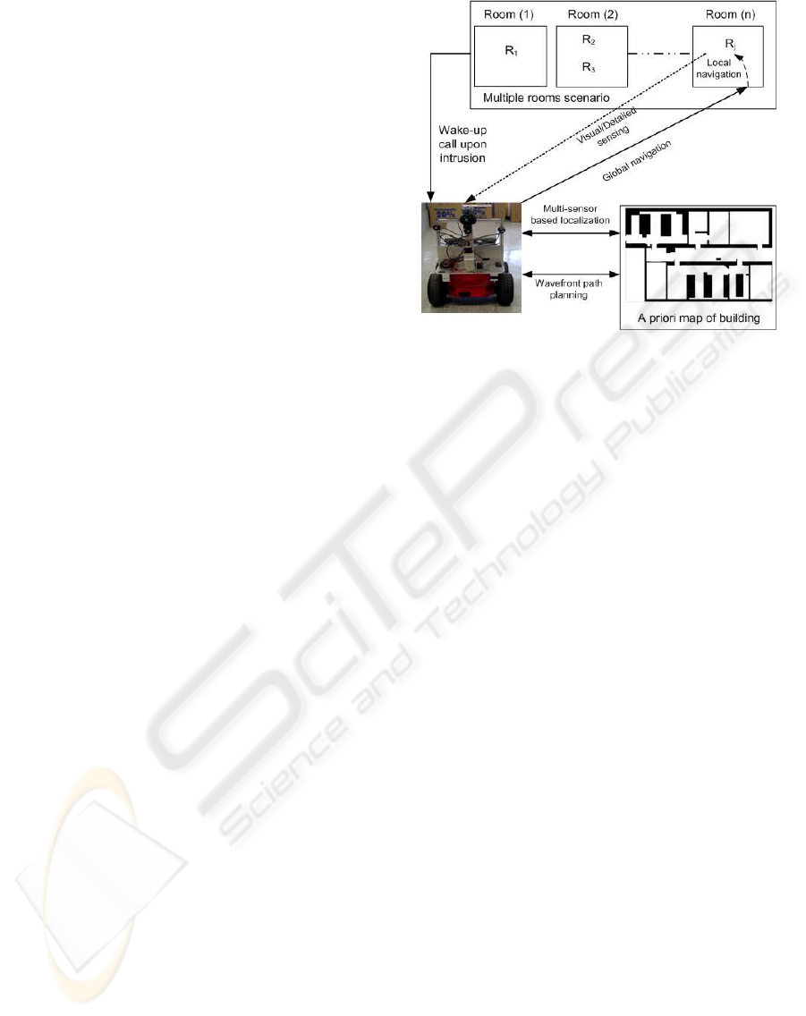
The generic surveillance strategy is shown in the fig-
ure 1 which illustrates a multiple room scenarios.
This work focuses mainly on building a robust and
the reliable surveillance system for an indoor envi-
ronments. Therefore, we have utilized standard tech-
niques for path planning and navigation (local and
global) whereas the process of localization is im-
proved using a multi-sensor localization process.
As shown in figure 1 every room is deployed with
radio transmitters R
n
. The radio transmitters are con-
nected to motion detectors and generate an alarm via
the network upon the detection of any physical in-
trusion. The alarm message contains the transmit-
ter node identification number and its position. The
robot receives a wake-up call upon detection of intru-
sion and start to estimate its location using a multi-
sensor localization process. The shortest path from
the robot’s current position to the target position of
sensor node is generated using a wavefront based path
planning technique. The robot then navigates toward
the goal position while avoiding obstacles and per-
forms visual sensing upon reaching its goal. The
next sections provide a detailed discussion on differ-
ent modules.
2.1 Establishing a Wireless Sensor
Network
The first step involves the establishment of wireless
sensor network. The j=n-2 of total n radio nodes
R
n
are deployed in an area which the robot moni-
tors. They are static and connected to motion de-
tectors. The rest of the two nodes are attached to a
mobile robot and a console PC. A mobile robot re-
ceiver picks up status messages generated by static
transmitter nodes. The network is established among
radio transmitters using a table based routing scheme.
Each transmitter sends a beacon message to its neigh-
boring nodes which acknowledges the beacon mes-
Figure 1: Generic surveillance strategy of a mobile robot.
sage with routing table messages. This is necessary to
provide information about the next possible hop. Af-
ter an exchange of acknowledgement messages, each
node then broadcasts node detected messages to up-
date the routing table. Each motion detector has its
defined vicinity in which it can detect the movement
of different physical objects. Whenever a movement
is sensed by a transmitter node, it generates an alarm
which is received both by a mobile robot and the con-
sole PC. The alarm contains an identification number
of the transmitter node. The position of the transmit-
ter node on a priori map is identified by its number.
Figure 2 displays a graphicaluser interface (GUI) run-
ning on the console PC. The placement and status of
each radio transmitter node in an established sensor
network can be monitored through this designed GUI.
It is dynamic in a sense that it is capable to load a
map of a new operational environment and can adjust
the placement of the sensor nodes in the new environ-
ment.
2.2 Localization: Pose Estimation of a
Mobile Robot
Once an alarm is generated, the next step is to esti-
mate the location of a mobile robot which is assumed
to be unknown in the begining. In the current appli-
cation, the presence of a noise in the sensor models
and the imprecise actuator control of mobile robots
makes it difficult to accurately estimate the robot posi-
tion even for the known environments. A fast conver-
gence of the estimated position is another challenge
in the field of localization. In this regard, we propose
a multi-sensor based localization scheme to deal with
different issues faced during the position estimation
ICINCO 2009 - 6th International Conference on Informatics in Control, Automation and Robotics
294
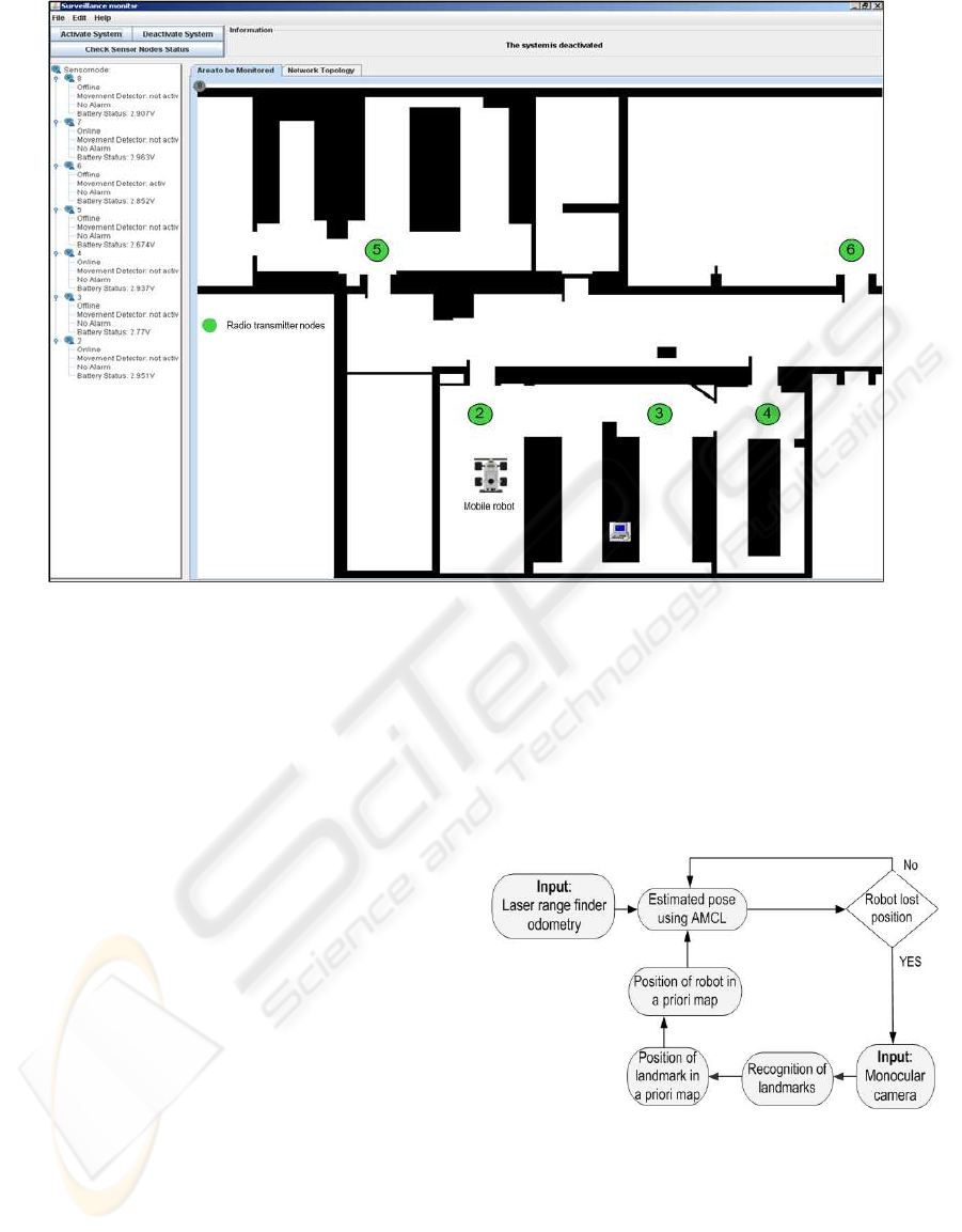
Figure 2: Graphical user interface on the console PC.
of a mobile robot in an indoor environments. A mo-
bile robot performs the localization using an adaptive
Monte Carlo localization (AMCL) technique (Pfaff
et al., 2006). It is applicable to both local and global
localization problems. It is simply a variant of parti-
cle filtering (Arulampalam et al., 2002). It makes use
of the recursive Bayesian filtering scheme in order to
estimate a mobile robot location in an environment. It
also requires a decent sensor model and the motion
model of a mobile robot. It is worth mentioning here
that AMCL is very much capable to handle complex,
multimodal (non-Gaussian) posterior distributions of
a mobile robot locations. However, it has difficulties
when the pose of a mobile robot is high dimensional
because the number of particles increases exponen-
tially with the dimensionality of state space and hence
increases the computational complexity of the overall
process. This is yet an open research issue in the field
of SLAM and the human body tracking applications.
AMCL estimates the pose from an input data of
an odometry sensor and a laser range finder. AMCL
requires an accurate sensor model but it is difficult to
design a perfect sensor for the varied environments.
For example there are cases where a laser range finder
fails to provide the reliable range data, especially in
the presence of glass windows or doors. The presence
of the bright light and the vibrations produced by a
mobile robot also affect the performance of a laser
range finder. In order to deal with these problems, we
have implemented a multi-sensor based localization
strategy as shown in figure 3. The scheme is inspired
by the multi-sensor data fusion techniques presented
in (Castellanos and Tardos, 1999) and (Wu and John-
son, 2008) with an aim to deal with drawbacks of a
laser range finder with an added advantage of lower-
ing the convergence time during pose estimation pro-
cess. The main steps involve are:
Figure 3: A Multi-sensor localization process.
1. Exploration of the Environment. A mobile
robot explores an area using a monocular web
camera mounted on a mobile robot.
2. Recognition of Landmarks. We have selected
a segmentation method provided by (Aziz and
Mertsching, 2006) in order to recognize the dif-
ferent landmarks. The segmentation is reliable for
SURVEILLANCE SYSTEM USING A MOBILE ROBOT EMBEDDED IN A WIRELESS SENSOR NETWORK
295
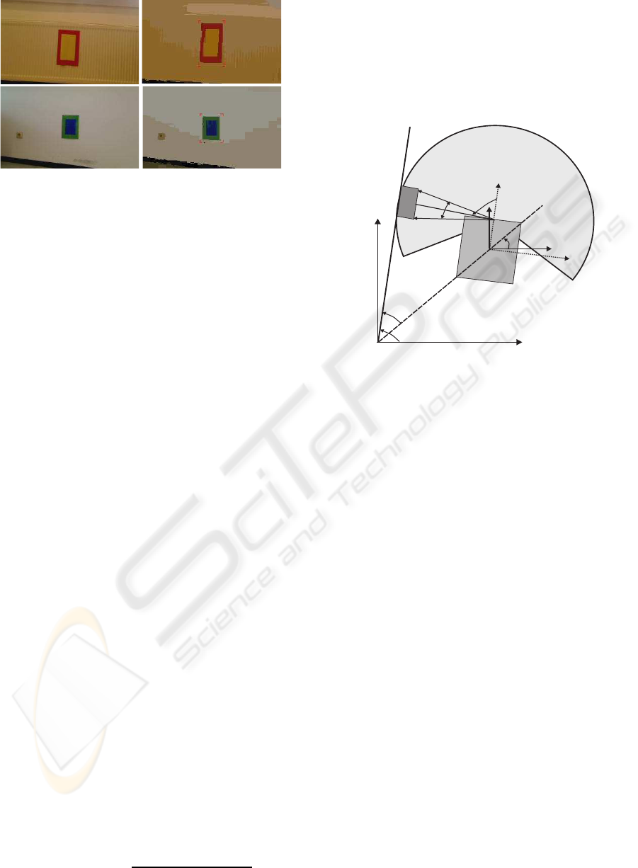
Figure 4: Left: original images and right: segmented out-
put.
indoor scenarios. Figure 4 displays different land-
marks and the segmented output. The landmarks
are placed at known positions.
3. Position of the Landmark in a Map. The de-
tected landmark is matched with known land-
marks to determine its global position coordinates
on the map.
4. Position of a Mobile Robot in a Map. The pose
of the robot is calculated using the landmark’s po-
sition and distance information obtained through
a laser range finder. The procedure is explained in
the subsequent section.
5. AMCL. The robot pose is provided to the AMCL
localization module as an initial position of a mo-
bile robot to estimate its actual pose in the map.
6. Relocalization. Steps 1-5 are repeated whenever
the robot position is lost during navigation appli-
cations.
2.2.1 Orientation of Robot
Figure 5 illustrates the method to find out the orien-
tation of the robot θ
r
relative to a priori map in the
world coordinates with following details:
1. The pose information of the wall (x
wall
, y
wall
,
θ
wall
) relative to the world coordinates is known.
2. The orientation of the camera θ
cam
relative to the
robot coordinates is also known.
3. The landmark is detected such that it should be in
the middle of an acquired visual input. A laser
range finder and a camera both are identically ori-
ented with respect to robot coordinates.
4. The angles θ
s1
and θ
s1
are computed by adding
and subtracting 10 degrees to θ
cam
.
5. The distances d
1
and d
2
are then calculated using
a laser range finder for θ
s1
and θ
s2
respectively.
6. The angle θ
w−r
is calculated to find out the wall
to a mobile robot orientation.
θ
w−r
= arctan
d
2
cosθ
s2
− d
1
cosθ
s1
d
2
sinθ
s2
− d
1
sinθ
s1
(1)
7. Finally, the orientation of a mobile robot relative
to the wall θ
r
is computed using:
θ
r
= θ
wall
− θ
w−r
(2)
Finally a mobile robot location relative to a priori
map is found out using θ
r
and range information of
landmark.
Landmark
LaserFoV:240
0
x
world
y
world
x
r
-y
r
θ
r
θ
w-r
θ
wall
θ
s1
θ
s2
d
1
d
2
Wall
θ
cam
x
world
y
world
A mobile robot
Figure 5: Pose estimation of a mobile robot in a priori map
using multi-sensor localization.
2.3 Navigation
After estimating the global position of a mobile robot
in a known map, the next step is to navigate a mobile
robot to a goal location. The whole procedure of nav-
igation is shown in figure 6. When any of the radio
transmitters detects a motion in its vicinity, it gener-
ates an intruder alarm signal. It is then broadcasted to
other wireless sensor nodes. This alarm signal pro-
vides the identification number (IN) of a particular
transmitter node which generated an alarm. The IN
is then found out using a table which contains a list
of coordinate position of different transmitter nodes
and this position is considered as a goal location for
the navigator module. The goal location is needed
to find a desired path from the actual position of the
robot. The desired path is calculated using a path
planning algorithm. Path planning is a well discussed
topic in the field of a mobile robot navigation. We
have selected the wavefront path planning algorithm
(Behring et al., 2000) due to its suitability with grid
based maps. The wavefront planning algorithm cal-
culates a list of waypoints between a mobile robot
position and a goal location. This list is necessary
to generate the shortest possible path among them af-
ter taking into account the size of the robot and a safe
distance from different obstacles. Once the success-
ful path is discovered, the next step is to navigate a
mobile robot between its present location and a goal
ICINCO 2009 - 6th International Conference on Informatics in Control, Automation and Robotics
296
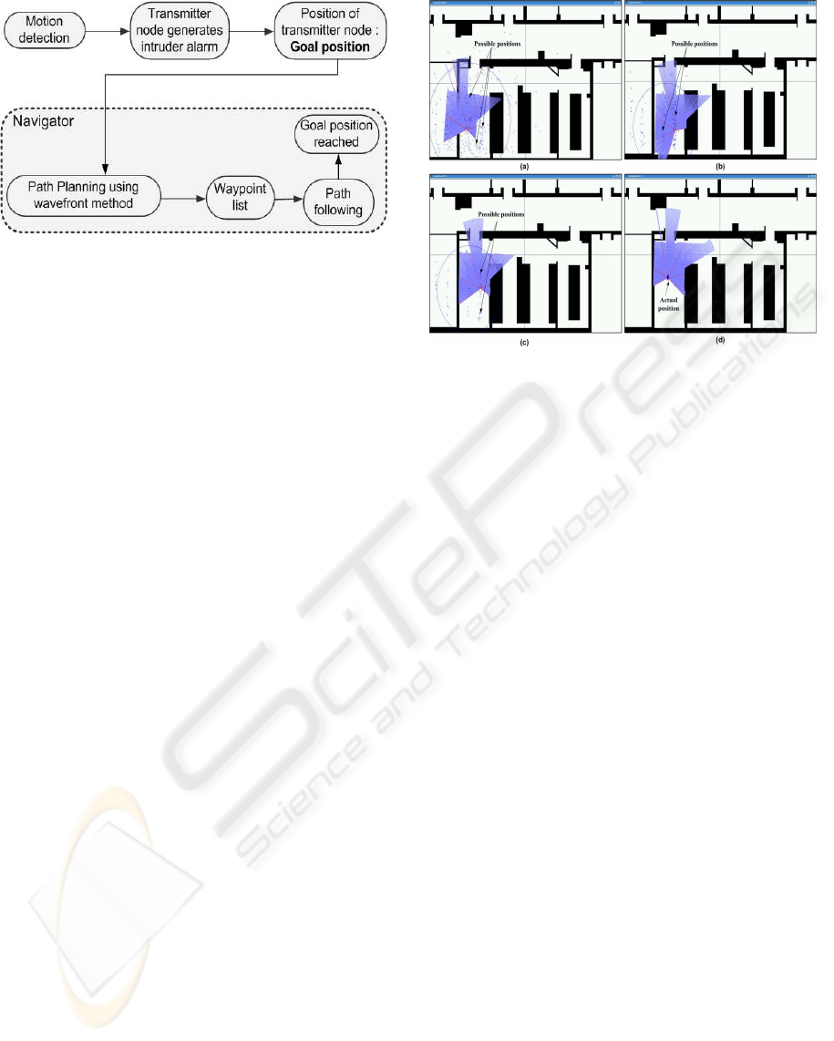
Figure 6: Navigation process.
by making use of the robust path following method.
This also requires an integrated obstacle avoidance
behavior for both the static and the dynamic obsta-
cles. Normally, the list of static obstacles is known
through an a priori map while a well defined local
navigation strategy is required to deal with dynamic
obstacles. There are different methods to perform this
kind of navigation. We have utilized the nearness di-
agram (Minguez and Montano, 2004) approach. This
approach provides a good methodology to avoid static
as well as dynamic obstacles for indoor environments.
The robot then follows a generated path and navigates
safely toward its goal. Once it reaches the goal loca-
tion, it generates a goal reached message. There is a
provision to perform an exploration of the goal loca-
tion surroundings with the help of an available visual
sensor. This also enables a console PC to monitor a
suspected area. The experiments and their outcomes
are discussed in the next section.
3 EXPERIMENTS AND
DISCUSSION
The experiments are conducted at GET lab, Univer-
sity of Paderborn. We used the customized Pioneer
3AT robot GETbot equipped with the two dimen-
sional and a 240 degreefield of view laser range finder
(Hokuyo, 2009) and the pan-tilt based webcam for ex-
ploring an environment and avoiding the obstacles.
Tmote sky sensor nodes (Tmote, 2009) are used as
wireless nodes in a static WSN. They are attached
to the motion detector. The map of the experimen-
tal setup and a pre-deployed static WSN of 6 nodes
are shown in figure 2. It is a regular office environ-
ment with narrow door openings of about 90 cm. The
nodes are deployed on the ceiling. Figure 1 shows
the experimental mobile robot being employed. The
surveillance strategy is implemented using a player-
stage (Collet et al., 2005) robot control toolkit.
Figure 7: Robot localization using standard AMCL (a) T=0
s and particles=10,000. (b) T=10 s and particles=5000. (c)
T=15 s and Particles=1000. (d) T=20 s and particles=100.
The experiments are performed on the basis of
event handling and the generation of an alarm is con-
sidered as an event. The two different navigation be-
haviors are generated according to following condi-
tions:
1. The first alarm received by a mobile robot is con-
sidered as the priority alarm which is then locked
to reach the goal location. The alarms received
afterwards are considered as the false alarms.
2. The last alarm received by a mobile robot is con-
sidered as a priority alarm.
A mobile robot reaches its goal location area with an
accuracy of 0.25 meters. It is set as a parameter during
the path computation step. The availability of an exact
map of an environment increases the robust behavior.
The results of localization performed using standard
AMCL is shown in figure 7. The initial position of a
mobile robot is unknown. Once a mobile robot starts
its localization process, it begins matching the scans
obtained through a laser range finder with a known
map of an environment and awards high weightage to
most probable matched places. In this way, a mobile
robot tends to localize itself to most probable position
over the time. The exact match sometimes takes up
to several seconds to find an accurate estimation of a
mobile robot pose as shown in figure 7. Symmetric
environments are prone to false position estimations.
In order to avoid these problems we have placed land-
marks as shown in figure 4 at different places in the
experimental scenario. It is important to highlight that
the size and placement of landmarks is an important
factor. The landmarks must be placed at the height of
a laser range finder. This is advantageous in avoiding
collisions with glass doors which are otherwise not
SURVEILLANCE SYSTEM USING A MOBILE ROBOT EMBEDDED IN A WIRELESS SENSOR NETWORK
297

detected by the employed laser range finder. The posi-
tions of landmarks on the map are known. The visual
sensor is then utilized to perform a multi-sensor based
localization process. This is quite useful in estimating
a mobile robot pose on the map. It also speeds up the
convergence process of the localization from around
20 seconds to 10 seconds. However, it depends on a
good landmark detection scheme. It has been tested
that this methodology works quite efficiently when-
ever the robot needs to perform self re-localization in
wake of position loss. Overall this results into a more
reliable and the efficient navigation behavior.
4 CONCLUSIONS AND FUTURE
DIRECTIONS
We have presented a generic surveillance strategy for
a guard robot using a wireless sensor network. The
scheme has been implemented and worked out for
different indoor scenarios. Our approach presents an
improved localization process by employing a multi-
sensor localization technique. It also allows the in-
tegration of different sensors to deal with different
kinds of environment. The results show that a fast
convergence of the localization process is achieved
while effectively reducing the effects of a sensor
noise. In the future work, we intend to see how the
system performs reliably providing a relaxation in as-
sumed conditions and parameters. The detailed com-
parison of a proposed localization strategy with other
standard techniques is also an immediate step.
ACKNOWLEDGEMENTS
The authors would like to thank the higher education
commission of Pakistan and the DAAD of Germany
for supporting the research studies at University of
Paderborn, Germany. The authors would also like to
thank Mr. D. Fischer, Mr. M. Z. Aziz and Mr. S.
Shafik for providing useful comments.
REFERENCES
Arulampalam, S., Maskell, S., Gordon, N., and Clapp,
T. (2002). A tutorial on particle filters for on-
line nonlinear/non-gaussian bayesian tracking. IEEE
Trans. on Signal Processing, 50(2):174–188.
Aziz, M. Z. and Mertsching, B. (2006). Color segmentation
for a region-based attention model. In Proceedings of
12th Workshop Farbbildverarbeitung, pages 74–83.
Batalin, M. A., Sukhatme, G. S., and Hatting, M. (2004).
Mobile robot navigation using a sensor network. In
Proceedings of IEEE Intl. Conf. on Robotics and Au-
tomation, pages 636–641.
Behring, C., Brancho, M., Castro, M., and Moreno, J.
(2000). An algorithm for robot path planning with
cellular automata. In Proceedings of Intl. Conf. on
Cellular Automata for Research and Industry, pages
11–19.
Castellanos, J. A. and Tardos, J. D. (1999). Mobile robot
localization and map building - A multi-sensor fusion
approach. Kluwer Academic Publishers.
Collet, T. H. J., MacDonald, B. A., and Gerkey, B. P. (2005).
Player 2.0 : Toward a practical robot programming
framework. In Proceedings of Australian Conf. on
Robotics and Automation.
Corke, P., Peterson, R., and Rus, D. (2005). Networked
robotics: Flying robot navigation with a sensor net-
work. Springer Tracts in Advanced Robotics, 15:234–
243.
Durrant-Whyte, H. and Bailey, T. (2004). Simultaneous lo-
calization and mapping (slam): Part i the essential al-
gorithms. Robotics and Automation Magazine, 13:99–
110.
Fresse, U. (2006). A discussion of simultaneous localiza-
tion and mapping. Autonomous Robots, 20(1):25–42.
Hokuyo (2009). Laser range finder URG-LX04.
www.hokuyo-aut.jp/02sensor/07scanner/urg.html,
site accessed: 22.02.2009.
Minguez, J. and Montano, L. (2004). Nearness diagram
navigation (nd) : Collision avoidance in troublesome
scenarios. IEEE Trans. on Robotics and Automations,
20(1):45–59.
Montemerlo, M., Thrun, S., Koller, D., and Wegbreit, B.
(2003). Fastslam 2.0 : An improved particle filtering
algorithm for simultaneous localization and mapping
that provable converges. In Proceedings of Intl. Joint
Conf. on Artificial Intelligence, pages 1151–1156.
Pfaff, P., Burgard, W., and Fox, D. (2006). Robust monte-
carlo localization using adaptive likelihood models.
In European Robotics Symposium, pages 181–194.
Springer-Verlag Germany.
Tmote (2009). Tmote sky nodes IEEE 802.15.4.
www.sentilla.com/pdf/eol/tmote-sky-datasheet.pdf,
site accessed: 22.02.2009.
Wold, J., Burgard, W., and Burkhardt, H. (2002). Robust
vision-based localization for mobile robots using an
image retrieval system based on invariant features. In
Proceedings of IEEE Intl. Conf. on Robotics and Au-
tomation, pages 359–365.
Wu, A. D. and Johnson, E. N. (2008). Methods for localiza-
tion and mapping using vision and inertial sensors. In
Proceedings of AIDA Guidance, Navigation and Con-
trol Conf. and Exhibit. AIAA 2008-7441.
ICINCO 2009 - 6th International Conference on Informatics in Control, Automation and Robotics
298
