
A LOW COST AND FLEXIBLE APPROACH
TO CAN CONFORMANCE TESTING
Imran Sheikh and Michael Short
Embedded Systems Laboratory, Department of Engineering, University of Leicester, University Road, Leicester, U.K.
Keywords: Controller Area Network, Conformance testing, Network protocol verification.
Abstract: Since its introduction in the early 1980’s, CAN has become the de-facto communications protocol employed
in vehicle and industrial control applications. Before any new product can claim to support CAN-
connectivity, compliance with the protocol at the physical and data link layers must be tested and verified.
To help standardize the requirements for such testing, ISO has set a draft standard specifically for CAN
conformance testing. Traditionally, CAN controllers and transceivers have been implemented at the silicon
level, either in the form of dedicated IC’s or as on-chip peripherals of embedded devices. The practical
implementation of CAN conformance testers has been realised using dedicated hardware and specially
written analysis software; this is a practical approach when testing and verifying conformance prior to high-
volume IC manufacture. However, recent years have seen an increased interest in the employment of CAN-
connected devices implemented by programmable logic devices such as FPGA’s. Such ‘soft core’
implementations are often in small-volume (or even one-off) batches. In such circumstances, for cost and
availability reasons, it may not be practical for developers to use traditional CAN-conformance testing
equipment. To help alleviate this problem, this paper proposes a low-cost and easily implemented method
which will allow developers to fully test a CAN soft core implementation. The method is based around
simple off-the-shelf development boards and the simple analysis tool Chipscope, and allows developers to
verify a CAN core against the relevant ISO standards. Finally, the paper describes the use of the test bed in
the verification of an open-source CAN soft core implementation.
1 INTRODUCTION
Conformance testing is an integral part of the
development stage of any network protocol
implementation. When components (or devices) pass
such conformance tests this ensures, to an acceptable
degree of confidence, that the implementation of the
given set of protocol specifications has been
correctly interpreted by the designers; and it also has
been instantiated in a form that is free from errors.
Since its introduction in the early 1980’s, the
Controller Area Network (CAN) protocol has
become the de-facto communications protocol
employed in vehicle and industrial control
applications (Bosch, 1991). In light of the popularity
of CAN, the ISO has developed a standard
exclusively aimed at CAN conformance testing.
Before any new equipment design can claim to be
CAN conformant, evidence is required that shows
that the testing procedures outlined in ISO 16845
(ISO, 2000) have been performed and passed
without problem. The ISO document not only
specifies different types of tests that must be
performed for conformance testing, but also
specifies a Test Plan (TP) architecture based on the
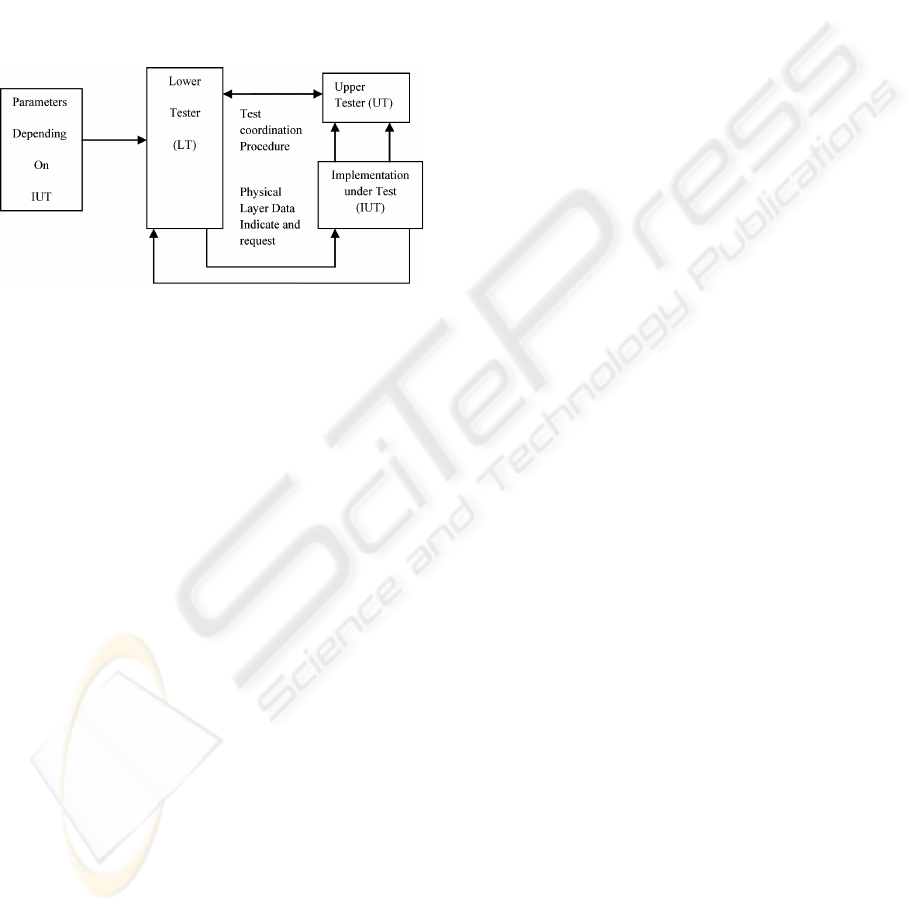
ISO 9646-1 (ISO, 1994). The required TP is shown
in figure 1. As can be seen from this figure, the TP
architecture indicates that the tester should be
divided into two parts. The first component is the
Lower Tester (LT) which provides the test pattern
generation and analysis. The second is termed the
Upper Tester (UT), which is required to contain the
software to control the CAN Implementation Under
Test (IUT). The UT is normally a host processor or
programmable device of some kind, and also
provides coordination to conduct the tests between
the LT and the IUT (Carmes et al, 1996). The UT
receives stimulus (with details of the test being
performed) from the LT, and generates messages
passed on to the IUT. The IUT then processes these
messages, and both the UT and LT components
monitor its behaviour for consistency with the CAN
protocol. If the result is satisfactory, the test is
97
Sheikh I. and Short M. (2009).
A LOW COST AND FLEXIBLE APPROACH TO CAN CONFORMANCE TESTING.
In Proceedings of the 6th International Conference on Informatics in Control, Automation and Robotics - Intelligent Control Systems and Optimization,
pages 97-104
DOI: 10.5220/0002215300970104
Copyright
c
SciTePress
considered passed and testing proceeds to the next
conformance test. It should be noted that the testing
procedures that are required to be implemented
include coverage of common error conditions,
randomized tests and also bit timing tests. Most tests
are critical, and the latter category – bit timing –
contains a number of tests that can be difficult to
localize, and a suitable means is required to capture
and display multiple logic signals over an
appropriate timescale. This typically requires the use
of dedicated hardware and Logic Analyzers
(Lawrenz, 1998a).
Figure 1: Conformance TP.
The motivation for the current work is as
follows. Recent years have seen an increased interest
in the employment of CAN-enabled devices
implemented by programmable hardware devices
such as FPGA’s. By their very nature, such ‘soft
core’ implementations are often needed in small-
volume (or even one-off) batches. In these
circumstances, cost and availability reasons often
dictate that it is not practical for developers to use
traditional CAN-conformance testing equipment. To
help alleviate this problem, this paper proposes a
low-cost and easily implemented method which will
allow developers to test a CAN soft core
implementation for conformance to the relevant
standard without the need for expensive or
proprietary hardware interfaces and logic analyzers.
The remainder of the paper is organized as
follows. Section 2 discusses several approaches to
CAN conformance testing that have been previously
described. Section 3 describes the proposed test bed,
and Section 4 presents two case studies that illustrate
its use. Section 5 presents a comparison of the
proposed approach to several other techniques,
whilst Section 6 presents our initial conclusions.
2 PREVIOUS WORK
One of the earliest CAN prototype controllers was
named DBCAN (Kirschbaum, 1996). This
implementation was tested using a logic analyzer
and a pattern generator circuit. As there was no
standard for conformance testing at the time the
prototype was developed, a commercial basic (as
opposed to full) CAN controller was used as
benchmark for verification. A major disadvantage of
this scheme was the use of external interface
modules to visualize the state of different DBCAN
registers, and the testing procedure was somewhat
limited in the number of signal channels that could
be simultaneously analyzed. Since this is a needed
requirement in the case of ISO standard
conformance testing – the ability to visualize the
state of large numbers of CAN registers
simultaneously is a prerequisite – such a setup is
limited in this respect.
A slightly different verification technique was
reported by (Nimsub et al, 2005). Their technique
employed custom design boards with 8051
microcontrollers and SJA1000 CAN controllers, but
this method involved the design of specialized
interface hardware and boards to assist with the
testing plan. Specialised verification architecture for
testing automotive protocols (including CAN) at
both the module and chip level was proposed by
(Zarri et al. 2006). Again, this work requires a
specially designed CAN verification component as
part of the silicon, while the selection and
implementation of actual test sequences, along with
the selection of a suitable means to monitoring bus
signals, is left open for the tester.
With respect to soft core CAN implementations,
the CAN e-Verification (CANeVC) test bench has
previously been described (CANeVC 2005). This
commercial test facility requires a CAN
specification core to be embedded in the netlist; this
core then runs specific tests to verify the behaviour
of the CAN soft core. Again, this technique involves
a time consuming development of a test bench using
an expensive commercially available verification IP
; additionally, compatibility issues often arise when
using CAN implementations other than the
proprietary implementation (DiBlasi, 2003), and
only a limited number of programmable logic
devices are supported. Finally, several experimental
implementations (such as that reported by (Ferreira
et al. 2005) to measure single parameters - such as
CAN bit errors - rather than perform complete
conformance testing have been described in the
literature. Such implementations have typically used
complex and non-trivial means, requiring
customized hardware and software. In summary
then, it can be observed that - to date – specialised
ICINCO 2009 - 6th International Conference on Informatics in Control, Automation and Robotics
98
hardware and / or software has been required to
assist with CAN testing plans. In the following
Section, a novel testing approach that relies only
upon the use of low-cost, standard off-the-shelf
hardware and software is described.
3 PROPOSED TEST BED
An ongoing project required the development of a
conformant soft core controller for the CAN
protocol (Sheikh et al. 2008). After the Verilog
(IEEE, 2001) implementation of the CAN
specifications for such a controller had been
completed, it was required to be tested and verified
in accordance with the relevant ISO standard (ISO
16845, 2000). Real-time testing of a CAN
implementation is quite a complicated procedure,
and – in this case – for practical reasons, no
specialized hardware and software was available to
generate the required testing patterns and monitor
the behavior of the CAN soft core. For this reason, it
was decided to use only low-cost off the shelf
components.
In addition to these standard hardware parts, the
Chipscope analysis tool (Xlinx, 2000) was used to
visualize and capture the behavior of the soft core,
allowing verification of the testing results.
Chipscope is a Xilinx testing tool which is
implemented the by inserting a small core onto the
device to be monitored, allowing multiple signal
channels to be captured via a JTAG interface. Up to
16 internal signal ports can be analyzed in a single
core, and each port can have up to 256 signals.
Multiple cores can be attached in a FPGA to
increase the number of signals (Oltu et al. 2005). In
comparison to other means for capturing multiple
FPGA signals, Chipscope retains the key features
required but is a fraction of the cost. Additionally, to
support one-off conformance testing plans without
causing excessive costs, a fully-featured evaluation
version is available for a 60 day period – a full
testing plan can be performed in such a timeframe.
Hence these features of Chipscope made it an
obvious choice for our CAN conformance test bed.
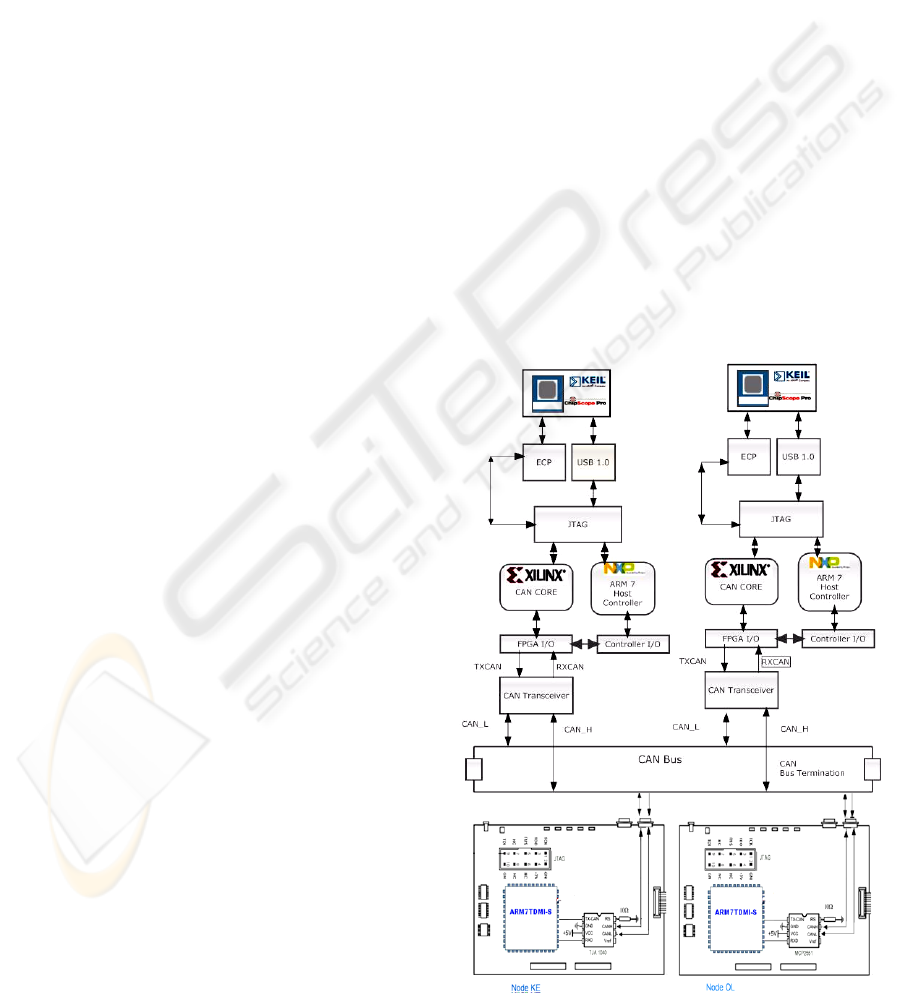
The new test facility is shown schematically in
figure 2. In the next paragraphs we give a full list of
the hardware and software components and tools
used in building the Test Bed.
3.1 Hardware
1) Two FPGA (XC3S500E programmed with
CAN soft core) + ARM7 (LPC2138 as Host
controller) boards. These boards are named as
SC1 and SC2.
2) Two ARM7 Microcontroller boards with
Integrated CAN controller and CAN transceiver
for CAN bus interfacing named as KE and OL.
3) The SC1 and SC2 are connected to the bus
using PCA82C250 CAN transceivers.
4)
Parallel JTAG cable for downloading and
analyzing signals for FPGA.
5)
USB JTAG cable for downloading and
debugging the ARM7 Microcontroller boards.
3.2 Software
1) Xilinx ISE for soft-core programming,
synthesis, routing and programming the FPGA.
2) Chipscope Pro (Xilinx, 2000) is used as analysis
tool (60 day evaluation version available).
3) The Keil uVision 3 IDE with free ARM tools C
compiler was chosen for programming and
debugging the Microcontroller boards.
As can be seen, the test bed has been made using
COTS hardware and also taking in care the structure
Figure 2: CAN Conformance test bed.
A LOW COST AND FLEXIBLE APPROACH TO CAN CONFORMANCE TESTING
99

of the Test Plan given in ISO 9646-1. The test bed
consists of two instances of the IUT; the main
purpose of using the second IUT is to generate errors
on the CAN bus and special conditions which were
either the pre-requisite for a test case or generating
special bit stream during a test for verifying the
behavior of the IUT, hence the second instance of
IUT is moreover working as the LT in reference to
the ISO9646-1 TP. The ARM boards with integrated
CAN Controllers were used either as receivers /
transmitters to verify the conformance of the IUT
with widely used CAN controllers, and were also
employed to generate bit errors on the CAN bus
using an interrupt generation mechanism. Such a
scheme is highly synchronized as the bit inversions
were done at the specific point where it was
required; the methodology employed for test pattern
generation is described in the next Section.
3.3 Test Pattern Generation
When using pattern generators test vectors are
required to be first stored, and are sent on the CAN
bus only when required – thus putting the IUT in
different states and allowing its behaviour and
responses to be analyzed. In our proposed test bed
we have used FPGA based pattern generation, which
is not only economical as no extra price was added
to the test setup but also it is added as a Verilog
module to the main CAN Core (IUT SC2 in Figure
2). This helped us to accurately produce these
special conditions; for example in test case 1 (to be
reported in the next Section) it was needed to
produce extra dominant bits on the CAN bus after an
IUT working as a transmitter send an Error Frame
(ISO 16845, 2000). This test pattern was easily
achieved by modifying the Verilog module for Error
Flag generation to produce extra dominant bits, as
illustrated by the Verilog code fragment shown
opposite.
This is a simple example of pattern generation
using HDL code. All of the required test patterns
may be generated in this way, giving full
controllability on the test case generation. In
addition, tight synchronization of events can be
achieved – a hardware signal from the core to one of
the secondary ARM boards, at a certain point during
the transmission of a CAN message, can be sent.
This signal may be used to generate an interrupt on
the ARM board – the interrupt latency is
significantly less than a CAN bit-time, even at 1
Mbits/s – and within this ISR the ARM board can,
for example, inject a bit error, The following Section
describes two case studies to further highlight the
operation of the test bed.
reg [3:0]
Error_Flag_Counter;//changed from reg
[2:0]
always @ (posedge Clock or posedge
Reset)
begin
if (rst)
Error_Flag_Counter <= 4'd0;
else if (Error_Frame_End |
Error_frame_Start)
Error_Flag_Counter <=#delay 4'd0;
//changed from 3'd7
else if (Error_Frame &
Transmit_Instance &Error_Flag_Counter <
4'd11))
Error_Flag_Counter <=#delay
Error_Flag_Counter + 1'b1;
end
always @ (Error_frame or
Error_Flag_Counter )
begin
if (Error_frame) begin
if (Error_Flag_Counter < 4'd11)
//changed from 3'd7
begin
if (Node_Error_Passive)
Tx_CAN = 1'b1;
else
Tx_CAN = 1'b0;
End
4 CASE STUDIES
The proposed test facility was employed to test the
CAN conformance of the custom created CAN soft
core, written in Verilog. As the number of total
number of test cases to consider in any single CAN
conformance test plan is numerous, it is beyond the
scope of the current paper to present comprehensive
test results; such test results are available in the form
of technical report (Sheikh & Short, 2009).
However, in this Section we will present two test
cases that help highlight the main features of the
proposed facility. Both tests were carried out
successfully, and are described in the following two
Sections.
4.1 Error Flag Longer than 7 Bits
This test is a part of the Error Frame Management
class in ISO 16845. The purpose of this test is to
verify that a CAN transmitter will only tolerate 7
dominant bits after sending its own Error flag. The
ICINCO 2009 - 6th International Conference on Informatics in Control, Automation and Robotics
100

case described below is for when the Error Flag is
elongated by 4 Dominant bits. This test involves two
instances of the IUT and the ARM7 Microcontroller
boards. The test will be setup using the following
organization:
1. Both the IUT’s must be in default state ready for
transmission or reception.
2. An error bit is to be introduced on the CAN bus
during an ongoing transmission.
3. The transmitter - after sensing the error - must
send an error frame of 6 dominant bits due to its
Active Error state.
4. One of the receivers must send more than 7
dominant bits after receiving the Error flag.
5. The transmitter must not take these extra
dominant bits as an Error and shouldn’t send any
extra Error Frame, and should start to resent the
corrupted message.
The methodology employed was to modify one
of the soft core IUTs to carry out this requirement.
Any of the two IUT’s can take the role of transmitter
or receiver for any given test. In this case, the IUT
instance which will be acting as a receiver is
modified to generate an 11 bit Error Flag. The
snapshot of the events on the CAN bus was captured
with the help of Chipscope trigger mechanism
(Woodward, 2003). The observations on the
transmitter node from the Chipscope snapshot –
shown in figure 3 - are as follows:
1. On the Left of Marker ‘T’, the TX_state high
indicates an ongoing transmission. During data
transmission a Bit_Error is injected, indicated by
the bit inversion as CAN_Tx is recessive while
CAN_Rx is dominant (Bit inversion is done by
the KE node).
2. The Error Frame exists between markers ‘T’ and
‘O’ indicated by signal ‘Error_Frame’, the
Error_Flag is between Marker ‘T’ and ‘X’. The
end of Error Flag is indicated by a high
Error_Flag_Tx_over signal. The
Error_Flag_Counter three bit bus is indicating
the count of Error Flag bits sent.
3. If we note at Marker ‘X’ the CAN_Tx signal has
changed to Recessive but the CAN_Rx signal
remains Dominant for next 4 bits which is
because of the superimposition of the Error Flag
sent by the nodes on the CAN network.
4. The Error Frame is continued till Marker ‘O’ and
the end is shown by a low Error_Frame Signal
and a high Error_Frame_End Signal.
5. On the right of Marker ‘O’ we can clearly see
that after three sample points (intermission Field)
a new frame transmission has started indicated
by Tx_State, while Tx_State_ID[10:0] and
Tx_State_Data indicating different states of
transmission cycle.
The observations at the receiver node (shown in
figure 4) are as follows:
1. Marker ‘O’ indicates start of an Error_Frame, the
Tx_State low indicating the node is a receiver.
2. The Error_Flag_Counter is a 4 bit wide bus
which counts up to 11 bits i.e. it is sending 4
extra Dominant bits to the CAN bus to verify the
behaviour of transmitter node. The Dominant
bits can also be verified by the CAN_Tx and
CAN_Rx bits.
3. After the Error_Flag_Over Signal is set high the
CAN_Rx and CAN_Tx signals turns to dominant
for next seven bits indicating an Error frame
Delimiter.
4. Right of Marker 'X’ the Error_Frame signal is
low and after three Recessive bits (Intermission
Field) a new frame is started to be received
(Tx_State is low, CAN_Tx is recessive),
indicated by different Recieve_State_xxxx
signals).
4.2 Overload Frame Management
This test is a part of the Overload Frame
Management class (ISO, 2000). This test verifies
that an IUT will be able to transmit a data frame
starting with the identifier and without transmitting
SOF, when detecting a dominant bit on the third bit
of the intermission field. This test involves two
instances of the IUT and the ARM7 Microcontroller
boards. The test will be setup using the following
organization:
1. Both of the IUT’s must be in default state ready
for transmission or reception according to the
setup sent by the Host Controller.
The IUT acting as the Transmitter is set to
transmit two data frames as programmed in the
Host processor.
2. The Receiver IUT will be set to request an
Overload frame after reception of the first frame.
3. After the completion of the Overload Frame on
the third bit of the Intermission field (Normally
the Intermission field is a sequence of three
Recessive bits) is set to dominant by the Fault
injector node i.e. K.E.
4. The transmitter must not consider it as a bit error
and shouldn’t send a Dominant level SOF and
consider the dominant bit of the Intermission
field as the SOF.
A LOW COST AND FLEXIBLE APPROACH TO CAN CONFORMANCE TESTING
101
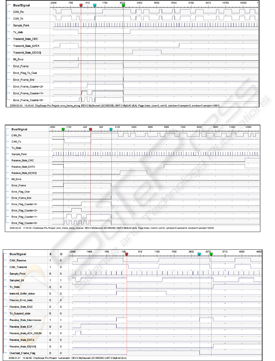
Figure 3: Transmitter snapshot for Test Case 1.
Figure 4: Receiver snapshot for Test Case 1.
F
igure 5: Transmitter snapshot for Test Case 2.
ICINCO 2009 - 6th International Conference on Informatics in Control, Automation and Robotics
102

5. Normal reception of the message should take
place.
This test was successful with desired results as
stated in the purpose of the test; the observation on
the transmitter node from the Chipscope - shown in
figure 5 – is as follows:
1. Left of Marker ‘T’ The Tx_state flag is high
indicating ongoing transmission,
Receive_state_Data and ACK_DELIM
indicating a successful transmission while the
node is error active.
2. At Marker ‘T’ there is an error on the
Receive_state_intermission field generating an
overload frame with Overload Flag of six
dominant and Overload delimiter of 8 bits as can
be seen by the count of sample point.
3. After the Overload frame an intermission field
signal can be seen at the Marker ‘X’.
4. The third bit of intermission field is is a
dominant bit as can be counted between Markers
‘X’ and ‘O’ the number of sample points is 2 and
the third sample point is a dominant bit.
5. Just after the Marker ‘O’ we can see the
Receive_State_ID [10:0] going high without any
SOF. The Identifier first 4 bits are dominant as
required by the Test case.
5 COMPARATIVE STUDY
When comparing the proposed testbed with previous
methods, the first observation is that the current
facility does not require the use of expensive CAN
PC interface cards which are normally required for
CAN conformance testing (Lawrenz, 1998b). Such
cards also require specialized software (along
hardware and interface cables) which can adds to the
cost and complexity of the setup. In the proposed
implementation the internal state of CAN IUT is
analyzed directly using Chipscope, and also by using
the Keil uVision to debug on the ARM boards. In
addition, there are several key advantages of our
proposed test bed using Chipscope over hardware
logic analyser systems:
1. The standard bench analyzers doesn’t show
enough signals as required in case of CAN
conformance as illustrated in section 4. There are
Logic analyzer systems which can show large
number of signals simultaneously with large data
widths but there prices are 10 times more than
Integrated Logic analyzer.
2. Normal Bench analysers can show Mega
samples, while the Chipscope is limited to a
Sample width of 16K, we overcome this problem
by using Digital clock Manager which can divide
or multiply the system clock by ‘n’ times, the
board we used in our system can divide the
system clock by 16 times hence we were able to
capture 16 times more sample than on system
clock which can easily capture 3 to 4 complete
CAN messages in a single trigger.
3. Additional probes with wide numbers of I/O pins
are required to interface with the Logic analysers
while Chipscope can carry magnitude of these
signals using a simple JTAG cable, although
there are few solution like Agilent’s FPGA trace
port (Agilent, 2003) which use a simple interface
to analyse multiple signals but it also requires a
specialized hardware and Chipscope pro tool.
4. Not only all I/O signals are accessible through
Chipscope but also internal wires can be traced
(Lee, 2007) which are really helpful in
Conformance testing specially when setting up
triggering conditions we have lot more options to
setup a trigger condition for example in the test
cases discussed it is really easy to setup a trigger
condition to wait for an Error Frame flag signal
goes to high to analyze an error condition, while
for external Logic analyzers only I/O signals are
available.
6 CONCLUSIONS
In this paper we have presented a low cost and
flexible approach to CAN conformance testing in
accordance with the ISO standards. It has been
shown that the facility is capable of performing the
full range of test required to show conformance to
the relevant CAN standard (Bosch, 1991), (ISO,
2003). In conclusion, this facility can be assembled
and used for a fraction of the cost of a ‘regular’ test
facility for CAN conformance. A full list of the how
each individual test may be implemented when using
a facility such as this has been described in a
technical report (Sheik & Short, 2009), allowing the
facility to be implemented by any third-parties
requiring a low-cost methodology to test for
conformance of a CAN soft-core.
As a final note, it can be seen that test facility
that has been described is not restricted to the CAN
protocol, and – with suitable modifications – can be
used to test conformance of many alternate network
protocols, for example TTP/C (TTA, 2003).
A LOW COST AND FLEXIBLE APPROACH TO CAN CONFORMANCE TESTING
103

ACKNOWLEDGEMENTS
This Paper is part of Imran Sheikh’s PhD studies
which is financed by NWFP University of
Engineering & Technology Peshawar, Pakistan.
REFERENCES
Agilent Technologies, 2003. Deep Storage with Xilinx
Chipscope Pro and Agilent Technologies FPGA Trace
Port Analyzer. http://cp.literature.agilent.com/litweb/
pdf/5988-7352EN.pdf
Bosch, R., 1991. CAN Specification 2.0, Postfach,
Stuttgart, Germany: Robert Bosch GmbH.
CAN 2.0 eVC, 2005. Yogitech SPA.
Carmes, E., Junier, C., and Aussedat, F., 1996. CAN
Conformance: Methodology and Tools, Keynote
speech, CAN in Automation Proceedings of 3rd iCC
1996, Paris, October 1996
Di Blasi, A., Colucci, F., and Mariani, R., 2003. Y-CAN
Platform: A Re-usable Platform for Design,
Verification and Validation of CAN-Based Systems
On a Chip, ETS- 2003 Symposium, May2003
Ferreira, J., Oliveira, A., and Fonesca, J., 2005. An
Experiment to Assess Bit Error Rate in CAN, In
Proceedings of 3rd International Workshop of Real-
time Networks (RTN 2004), Catania, Italy.
IEEE, 2001. Standard for Verilog Hardware Description
Language, IEEE standard 1364.
ISO, 1994. DIS 9646-1 The International Organization for
Standardization. Information technology-Open
Systems Interconnection-Conformance testing metho-
dology and framework.
ISO, 2000. DIS-16845, Road Vehicles- Controller Area
Network (CAN) - Conformance Test Plan
ISO, 2003. DIS 11898-1 Road vehicles – Controller area
network (CAN) – Part 1: Controller area network data
link layer and physical signalling.
Kirschbaum, A.; Renner, F.M.; Wilmes, A.; Glesner, M.,
1996. Rapid-prototyping of a CAN-Bus controller: a
case study, Rapid System Prototyping, 1996.
Proceedings. Seventh IEEE International Workshop on
, vol., no., pp.146-151, 19-21 Jun 1996.
Lawrenz, W., Kinowski, P., and Kircher,G., 1998a. CAN
Conformance Testing-The Developing ISO Standard
and Necessary Extensions, In Proceedings of
International Truck and Bus Meeting and Exposition
Indianapolis, Indiana, November 16-18, 1998.
Lawrenz, W., Kinowski, P. and Kircher, G., 1998b. CAN
Conformance Testing - State of the Art and Test
Experience, In Proceedings of 5th International CAN
Conference iCC’98, San Jose, California, November
1998.
Lee, T., Fan, Y., Yen, S., Tsai, C., and Hsiao, R., 2007. An
Integrated Functional Verification Tool for FPGA
Systems, Second International Conference on
Innovative Computing, Information and Control,
ICICIC '07, pp.203-203 5-7 Sept. 2007.
Nimsub, K., Dawi, K., Kyuhyung, C., Jinsang, K., and
Wonkyung, C., 2005. Design and Verification of a
CAN Controller for Custom ASIC, CAN in
Automation Proceedings of 10th iCC 2005.
Oltu, O., Milea, P., Simion, A., 2005. Testing of digital
circuitry using Xilinx Chipscope logic analyzer, In
Proceedings International Semiconductor Conference,
CAS 2005, vol.2, no., pp. 471-474, 3-5 Oct. 2005.
Sheikh, I., Short. M, and Pont, M., 2008. Hardware
Implementation of a Shared Clock Protocol for CAN:
A Pilot Study, In proceedings of 4th UK Embedded
Forum, Southampton, September, 2008.
Sheikh, I., and Short, M., 2009. CAN Conformance
Testing-A New approach, tech-report ESL-09-01,
ESL, Engineering Department, University of
Leicester.
TTA-Group, 2003. Time-Triggered Protocol TTP/C High-
Level specification Doc. Protocol Ver. 1.1, 1.4.3 ed.
Vienna, Austria, TTTECH.
Xilinx Inc, 2000. Chipscope integrated logic analyzer, San
Jose, CA 95124-3400. http://www.xilinx.com/ise/
optional_prod/cspro.htm
Woodward, J., 2003. The in-circuit debug of FPGAs,
CMP Media LLC, New York, Embedded Systems
Europe, vol 7, No 49, pp.16-17.
Zarri, G., Colucci, F., Dupuis, F., Mariani, R.,
Pasquariello, M., Risaliti, G. and Tibaldi,C., 2006. On
the verification of automotive protocols, In
Proceedings of Design, Automation and Test in
Europe, 2006. DATE '06. , vol.2, no., March 2006,
pp.6-10.
ICINCO 2009 - 6th International Conference on Informatics in Control, Automation and Robotics
104
