
FUZZY LOGIC BASED QUADROTOR FLIGHT CONTROLLER
Syed Ali Raza and Wail Gueaieb
School of Information Technology and Engineering, University of Ottawa
800 King Edward Avenue, Ottawa, ON, Canada
Keywords:
Quadrotor, Fuzzy Logic, Flight Controller.
Abstract:
Quadrotor unmanned aerial vehicles (UAVs) have gained a lot of research interest in the past few years, due to
the clear advantages posed by their vertical take-off and landing (VTOL),hovering capability, and slow precise
movements. These characteristics make quadrotors an ideal candidate for applications that require traversing
through difficult environments with many obstacles. Belonging to the helicopter rotorcraft class, quadrotors
are highly nonlinear systems that are difficult to stabilize. This paper proposes a fuzzy logic based flight con-
troller for an autonomous quadrotor. Two types of fuzzy logic controllers are implemented. The developed
flight controllers are tested in a quadrotor simulator and simulation results are presented to demonstrate the
performance of each controller. The controllers performances are also benchmarked against conventional con-
trol based techniques such as input-output linearization, backstepping and sliding mode control. In comparison
with other conventional control techniques mostly designed for indoor applications, the proposed fuzzy logic
based controllers showed satisfactory control of the quadrotor in the presence of various disturbances such as
sensor noise and high wind conditions.
NOMENCLATURE
The following notations are used in the paper:
F
n
represents the reference frame where the subscript
n ∈ {i,b,v,φ,θ}.
()
F
n
represents a point or a vector in reference frame
F
n
.
˙
(),
¨
() represent first and second time derivatives, re-
spectively.
R
F
2
F
1
∈ R
n×n
is the rotation matrix that maps frame F
1
to frame F
2
.
sθ = sinθ, cθ = cosθ.
I is the identity matrix.
COG is the quadrotor’s center of gravity.
P
T
= [p
x
p
y
p
z
] is the position of the quadrotor’s
COG.
M is the mass of quadrotor (including the motors).
m is the mass of one motor.
l is the length of the arms of quadrotor.
J
T
= [ j
x
j
y
j
z
] is the moment of inertia vector of the
quadrotor.
φ,θ,ψ are the quadrotor’s roll, pitch, and yaw angles,
respectively.
Ω
T
= [φ θ ψ] is the quadrotor’s orientation vector.
K
T
and K
τ
are motor constants.
T
motor
,τ
motor
,PWM
motor
are thrust, drag and PWM
value for motor ∈ { f, r, b, l}, the subscripts f, r, b,
and l, denote front, right, back, and left, motors re-
spectively.
1 INTRODUCTION
The motivation for employing robots in search and
rescue operations is multifaceted. However, the tech-
nology is still in its infancy and there are many issues
which need to be addressed. Search and rescue mis-
sions, as well as simulations, have demonstrated sev-
eral areas in which robot contributions need to be im-
proved(Fincannon et al., 2004). Advancesin comput-
ing, MEMS inertial measurement sensors, and com-
munications technology make it possible to achieve
autonomous performance and coordination of these
vehicles in test environments (Waslander et al., 2005).
But, achieving complete autonomous performance in
real environments is a milestone yet to be reached.
A quadrotor, as depicted in Figure 1, is a rotary
wing UAV, consisting of four rotors located at the
ends of a cross structure. By varying the speeds of
each rotor, the flight of the quadrotor is controlled.
Quadrotor vehicles possess certain essential charac-
teristics, which highlight their potential for use in
search and rescue applications. Characteristics that
105
Raza S. and Gueaieb W. (2009).
FUZZY LOGIC BASED QUADROTOR FLIGHT CONTROLLER.
In Proceedings of the 6th International Conference on Informatics in Control, Automation and Robotics - Intelligent Control Systems and Optimization,
pages 105-112
DOI: 10.5220/0002216601050112
Copyright
c
SciTePress
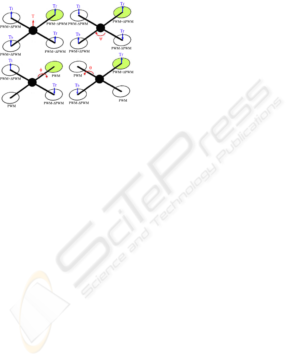
Figure 1: Conceptual diagram of the quadrotor.
provide a clear advantage over other flying UAVs in-
clude their Vertical Take Off and Landing (VTOL)
and hovering capability, as well as their ability to
make slow precise movements. There are also defi-
nite advantages to having a four rotor based propul-
sion system, such as a higher payload capacity, and
impressive maneuverability, particularly in traversing
through an environment with many obstacles, or land-
ing in small areas.
The quadrotor is an under-actuated system, in that
the four forces applied on the body result in move-
ments achieved in six degrees. Being a non-linear
system it offers an interesting and challenging con-
trol problem. The flight controller is responsible for
achieving the desired attitude, i.e. the orientation
(roll, pitch and yaw angles) of the quadrotor and also
the desired position of quadrotor in the space.
In past few years, a lot of research has already
been conducted on the modeling and control of a
quadrotor. Many control techniques are proposed in
the literature, however, their primary focus is mostly
for indoor flight control and therefore does not ac-
count for uncertainties. Lyapunov stability theory is
used for stabilization and control of the quadrotor in
(Bouabdallah et al., 2004a) (Dzul et al., 2004). Con-
ventional PD
2
feedback, and PID structures are used
for simpler implementation of control laws and com-
parison with LQR based optimal control theory is
presented in (Tayebi and McGilvray, 2006) (Bouab-
dallah et al., 2004b). Backstepping control is also
proposed with the drawback of higher computational
loads in (Guenard et al., 2005). Visual feedback is
used in many cases using onboard or offboard cam-
eras for pose estimation by (Altug et al., 2002) (Gue-
nard et al., 2008). And finally some fuzzy logic based
control techniques (Coza and Macnab, 2006), neural
networks (Tarbouchi et al., 2004) and reinforcement
learning (Waslander et al., 2005).
Fuzzy logic based control offers a great advan-
tage over conventional control, specifically in deal-
ing with nonlinear systems with uncertainties. In this
paper two fuzzy logic based flight controllers for an
autonomous quadrotor are proposed. Implementation
of the proposed control is carried out using Mamdani
and Sugeno fuzzy inferencing methodologies. The
advantage of the proposed methodology over other
conventional methods is the ability to achieve sta-
ble flight control under disturbances that are com-
mon in outdoor environments. Also the implemen-
tation is lighter in terms of computational loads as
compared to techniques such as backstepping control.
Both controllers are simulated and their performances
are benchmarked against various conventional con-
trol techniques. The results are presented to show the
satisfactory performance of the proposed fuzzy logic
based controllers despite the presence of various dis-
turbances, such as sensor noise and high wind condi-
tions.
2 QUADROTOR’S KINEMATICS
AND DYNAMICS
The flight behavior of a quadrotor is determined by
the speeds of each of the four motors, as they vary
in concert, or in opposition with each other. Hence,
a mathematical representation of the system can be
used to predict the position and orientation of the
quadrotor, based on its inputs. The same can further
be used to develop a control strategy, whereby ma-
nipulating the speeds of individual motors results in
the achievement of the desired motion. To derive a
mathematical model of the quadrotor, we need to de-
fine its kinematics and dynamics. The kinematics of
the quadrotor gives a relation between the position of
the vehicle in the inertial frame, and its velocity in the
body frame. The dynamics of the quadrotor provides
the relation between the applied body forces and the
resulting accelerations.
Three frames of reference are adopted;
1. The inertial frame, F
i
= (
−→
x
i
,
−→
y
i
,
−→
z
i
), is an earth-
fixed coordinate system with the origin located on
the ground, for example, at the base station. By
convention, the x-axis points towards the north,
the y-axis points towards the east, and the z-axis
points towards the center of the earth.
2. The body frame, F
b
= (
−→
x
b
,
−→
y
b
,
−→
z
b
), with its ori-
gin located at the center of gravity (COG) of the
quadrotor, and its axes aligned with the quadrotor
structure such that the x-axis
−→
x
b
is along the arm
ICINCO 2009 - 6th International Conference on Informatics in Control, Automation and Robotics
106

with front motor, the y-axis
−→
y
b
is along the arm
with right motor, and the z-axis
−→
z
b
=
−→
x
b
×
−→
y
b
.
3. The vehicle frame, F
v
= (
−→
x
v
,
−→
y
v
,
−→
z
v
), is the inertial
frame with the origin located at the COG of the
quadrotor. The vehicle frame has two variations,
F
φ
and F
θ
. F
φ
, is the vehicle frame, F
v
, rotated
about its z-axis
−→
z
v
by an angle ψ so that
−→
x
v
and
−→
y
v
are aligned with
−→
x
b
and
−→
y
b
, respectively. F
θ
is the F
φ
frame rotated about its y-axis,
−→
y
φ
, by a
pitching angle, θ, such that
−→
x
φ
and
−→
z
φ
are aligned
with
−→
x
b
and
−→
z
b
, respectively.
With the knowledge of the inertial frame position
state variables P
i
and the body frame speed state vari-
ables
˙
P
F
b
, the translational motion relationship is de-
rived as
˙p
x
˙p
y
− ˙p
z
F
i
=
h
R
F
b
F
v
i
T
˙p
x
˙p
y
˙p
z
F
b
where
h
R
F
b
F
v
i
T
∈ R
3×3
is the rotation that maps frame F
b
to
frame F
v
and is defines by
h
R
F
b
F
v
i
T
=
cθcψ sφsθcψ− cφsψ cφsθcψ+ sφsψ
cθsψ sφsθsψ+ cφcψ cφsθsψ− sφcψ
−sθ sφcθ cφcθ
The rotational motion relationship is also derived us-
ing the state variables involved:
˙
φ
˙
θ
˙
ψ
F
v
=
1 sφtanθ cφtanθ
0 cφ −sφ
0 sφ/cθ cφ/cθ
˙
φ
˙
θ
˙
ψ
F
b
.
The quadrotor’s dynamics is obtained by applying
Newton-Euler formulation.
MI
3×3
0
0 I
3×3
¨
P
F
b
¨
Ω
F
b
+
˙
Ω
F
b
M
˙
P
F
b
˙
Ω
F
b
I
˙
Ω
F
b
=
F
F
b
τ
F
b
where F
T
= [ f
x
f
y
f
z
] and τ
T
= [τ
φ
τ
θ
τ
ψ
] are ex-
ternal force and torque vectors applied on the quadro-
tor’s COG. τ
φ
, τ
θ
, and τ
ψ
are the roll, pitch and yaw
torques respectively. Hence, the models for the trans-
lational and rotational motion are
¨p
x
¨p
y
¨p
z
F
b
=
˙
ψ ˙p
y
−
˙
θ ˙p
z
˙
φ ˙p
z
−
˙
ψ ˙p
x
˙
θ ˙p
x
−
˙
φ ˙p
y
F
b
+
1
M
f
x
f
y
f
z
F
b
¨
φ
¨
θ
¨
ψ
F
b
=
j
y
− j
z
j
x
˙
θ
˙
ψ
j
z
− j
x
j
y
˙
φ
˙
ψ
j
x
− j
y
j
z
˙
φ
˙
θ
F
b
+
1
j
x
τ
φ
1
j
y
τ
θ
1
j
z
τ
ψ
F
b
where j
x
= j
y
= j
z
=
2Mr
2
5
+ 2l
2
m. The moment
of inertia is calculated by assuming the COG of the
quadrotor as a sphere of radius r and mass M. Also,
each motor is represented by a point mass m with arms
length l. The relationship between the quadrotor’s
overall thrust and drag produced by individual thrust
of the motors is defined by
T = T
f
+ T
r
+ T
b
+ T
l
, τ
ψ
= (τ
f
+ τ
b
) − (τ
r
+ τ
l
)
τ
φ
= l(T
l
− T
r
) , τ
θ
= l(T
f
− T
b
)
with
T
motor
= K
T
× PWM
motor
and τ
motor
= K
τ
× PWM
motor
for motor ∈ { f,r,b,l}. In matrix form, we get
PWM
f
PWM
r
PWM
b
PWM
l
= G ×
T
τ
φ
τ
θ
τ
ψ
where
G =
K
T
K
T
K
T
K
T
0 −l × K
T
0 l × K
T
l × K
T
0 −l × K
T
0
−Kτ Kτ −Kτ Kτ
−1
.
Including the forces and torques acting on the system,
the equations of motion become as defined in (1), with
g being the gravitational force.
3 FLIGHT CONTROLLER
DESIGN
Using the knowledge of the quadrotor’sbehaviorfrom
its equations of motion, a rule base is developed,
which serves as a starting point for developing the
fuzzy logic control strategy. These IF-THEN rules
will later be combined to form a fuzzy controller,
where fuzzy logic is used in a direct control scheme
applied for the flight control of the quadrotor.
Figure 2: Block diagram of fuzzy logic based flight con-
troller.
For attitude control, three fuzzy controllers are
designed to control the quadrotor’s roll (φ), pitch (θ)
FUZZY LOGIC BASED QUADROTOR FLIGHT CONTROLLER
107

¨p
x
¨p
y
¨p
z
F
b
=
˙
ψ ˙p
y
−
˙
θ ˙p
z
˙
φ ˙p
z
−
˙
ψ ˙p
x
˙
θ ˙p
x
−
˙
φ ˙p
y
F
b
+
−gsθ
gcθsφ
gcθcφ
+
0
0
− f
z
M
,
¨
φ
¨
θ
¨
ψ
F
b
=
j
y
− j
z
j
x
˙
θ
˙
ψ
j
z
− j
x
j
y
˙
φ
˙
ψ
j
x
− j
y
j
z
˙
φ
˙
θ
F
b
+
1
j
x
τ
φ
1
j
y
τ
θ
1
j
z
τ
ψ
F
b
(1)
and yaw (ψ) angles. Here FLC
φ
and FLC
θ
fuzzy
controllers are implemented in order to achieve
attitude stabilization. Three fuzzy controllers are
further designed for controlling the quadrotor’s
position. All the six fuzzy controllers, as depicted in
Figure 2, have the same structure with two inputs and
one output. The inputs are the error e, which is the
difference between the desired and the actual state
normalized to the interval [−1,+1], and the error
rate ˙e normalized to the interval [−3,+3]. Three
membership functions are used to fuzzify e, ˙e, and
the output U: µ
N
(e) = trapezoid(−1,−0.15,0),
µ
Z
(e) = triangle(−0.15,0,0.15),
µ
P
(e) = trapezoid(0,0.15,1), µ
N
( ˙e) =
trapezoid(−3,−1.5, 0), µ
Z
( ˙e) =
triangle(−1.5,0,1.5), µ
P
( ˙e) = trapezoid(0,1.5,3),
µ
N
(U) = trapezoid(−1,−0.85, 0), µ
Z
(U) =
triangle(−0.1,0,0.1), µ
P
(U) = trapezoid(0,0.85,1).
A unified rule base comprising nine IF-THEN
rules is developed for all the controllers. The devel-
oped rules are presented in Table 1.
Table 1: The rule base of the fuzzy controller.
e
N Z P
N N N Z
˙e Z N Z P
P Z P P
For the fuzzy controller to be independent of
the quadrotor’s parameters, the input and output sig-
nals of the designed fuzzy logic controllers are pre-
processed and post-processed, respectively. The pre-
processing process calculates the error e and error
rate ˙e and normalize them accordingly. The post-
processing process calculates the individual motor
PWM values by combining the outputs from the fuzzy
logic controllers and adding a priori-defined offset
to counter balance the weight of the quadrotor. The
PWM value of each motor is then computed as fol-
lows:
PWM
f
= Sat(U
Z
+U
Xθ
−U
ψ
+ Offset)
PWM
r
= Sat(U
Z
+U
Yφ
+U
ψ
+ Offset)
PWM
b
= Sat(U
Z
−U
Xθ
−U
ψ
+ Offset)
PWM
l
= Sat(U
Z
−U
Yφ
+U
ψ
+ Offset)
Being independent of the plant’s parameters sets
the pure fuzzy controllers apart from the conventional
control systems, which depends on the plant’s param-
eters. The fuzzy controllers are designed in light of
the behaviors extracted from the mathematical model
of the quadrotor, whereas conventional control tech-
niques are designed using the mathematical model of
the plant. Any change in the plant dynamics or param-
eters results in the failure of such conventional control
systems. In such situations, fuzzy systems are advan-
tageous over conventional control techniques.
Two different fuzzy inference procedures are im-
plemented: (i) a Mamdani fuzzy model, and (ii) a
Takagi-Sugeno-Kang (TSK) fuzzy model. The Mam-
dani fuzzy inference method uses a min-max opera-
tor for the aggregation and centroid of area method
for defuzzification. One problem with the designed
Mamdani fuzzy control is the high computational bur-
den associated to it when implemented on an embed-
ded system. To alleviate this problem, a zero order
Sugeno fuzzy model is implemented. In this model,
the output membership functions of the Mamdani
type FLC are replaced with fuzzy singletons N = −1,
Z = 0 and P = +1.
4 NUMERICAL RESULTS
To test the proposedfuzzy flight controllers, and study
their performances, a simulation environment is de-
veloped. The desired inputs from the user are the
translatory coordinates P
F
i
with respect to the inertial
frame, and the yaw angle ψ. The pitch and roll angles
are set to zero for achieving the desired attitude stabi-
lization, as shall be shown later.
To make the simulations more realistic, sensory
noise and environmental disturbances such as winds
are also taken into account. Different wind conditions
are generated based on the actual data from Canada
Weather Statistics, representing high, medium and
low wind conditions (Statistics, 2009). The angular
accelerations
¨
φ,
¨
θ, and
¨
ψ are degraded with a white
noise and then used as a feedback to the fuzzy con-
troller.
Several experiments are conducted on the two de-
signed fuzzy controllers. Due to the space limita-
tion, only three experiments are presented here. The
controllers performances are benchmarked against
those of similar control schemes found in the liter-
ature. The values used as the quadrotor’s dynamic
ICINCO 2009 - 6th International Conference on Informatics in Control, Automation and Robotics
108
0 5 10 15 20 25 30
−2
0
2
4
6
8
10
12
14
16
X−axis motion (m)
time (sec)
No noise, no wind
Noise, no wind
Noise and wind
(a)
0 5 10 15 20 25 30
−5
0
5
10
15
20
25
30
Y−axis motion (m)
time (sec)
(b)
0 5 10 15 20 25 30
−5
0
5
10
15
20
25
Z−axis motion (m)
time (sec)
(c)
0 5 10 15 20 25 30
−10
−5
0
5
10
15
20
25
30
Pitch angle (deg)
time (sec)
(d)
0 5 10 15 20 25 30
−40
−35
−30
−25
−20
−15
−10
−5
0
5
10
Roll angle (deg)
time (sec)
(e)
0 5 10 15 20 25 30
−5
0
5
10
15
20
25
30
35
Yaw angle (deg)
time (sec)
(f)
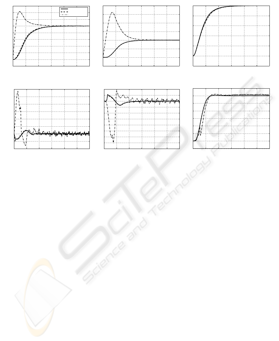
Figure 3: Experiment 1, Mamdani FLC’s performance with and without disturbances. Quadrotor states: (a) x-axis; (b) y-axis;
(c) z-axis (altitude); (d) pitch (θ); (e) roll (φ); and (f) yaw (ψ).
parameters are: M = 1.56 Kg, l = 0.3 m, J
x
=
J
y
= 0.08615 Kg·m
2
, J
z
= 0.1712 Kg·m
2
, K
T
= 5.45,
K
tau
= 0.0549, Offset = Mg/(4K
T
) = 0.7018.
In our first experiment the system’s initial states
are set to zero and the desired quadrotor’s position
and orientation are P
T
F
i
= [10,10,25] m and Ω
T
F
i
=
[0,0,30] degrees. The purpose of the experiment is to
show the performance of both controllers under dif-
ferent disturbance conditions. The experiment is re-
peated three times for each controller, first time with-
out any disturbances, second time with sensor noise
only, and third time with sensor noise and medium
north and east wind of 10m/s. The experimental re-
sults presented in Figures 3 and 4, demonstrate the
ability of both controllers to perform satisfactorily
despite the presence of sensor noise and wind dis-
turbances. The Mamdani fuzzy controller converges
to the desired states relatively faster than the Sugeno
fuzzy controller, however Sugeno shows better atti-
tude stabilization, specially in the presence of the sen-
sory noise and wind disturbances. The yaw angle
drift under wind disturbance is clearly visible in the
Sugeno results.
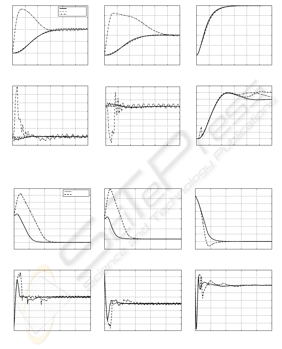
In second experiment, the position and attitude
stabilization of the proposed controllers are bench-
marked against feedback linearization based conven-
tional control technique, where a series of mode-
based, feedback linearizing controllers are imple-
mented for the stabilization and control of a quadro-
tor (Altug et al., 2002). The system’s initial states
are considered to be P
T
F
i
= [40,20,60] m and Ω
T
F
i
=
[45,−45, 0] degrees. In the presence of sensor noise
and winds, the system is supposed to stabilize all the
states back to zero. The experimental results are de-
picted in Figures 5 and 6. The stabilization achieved
by both proposed fuzzy controllers convergeto the de-
sired state faster than the feedback linearization tech-
nique. It is worth pointing out that the controller pro-
posed in (Altug et al., 2002) did not consider any type
of noise or external disturbances.
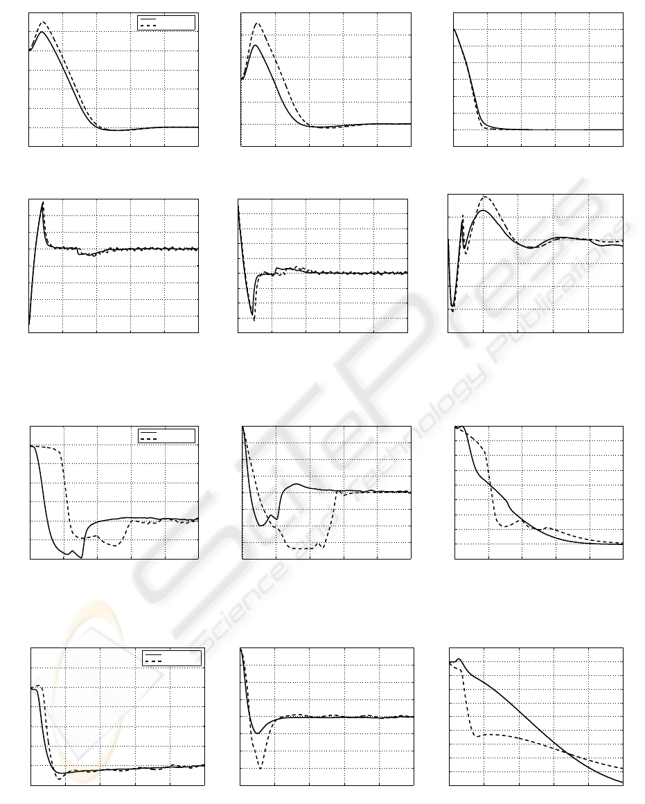
The third experiment benchmarks the proposed
fuzzy controllers with simulation results of a back-
stepping controller tuned for optimized nonlinear
control of a tethered quadrotor (Bouabdallah et al.,
2004b). The backstepping control offers high robust-
ness against large disturbances as compared to the
feedback linearization technique which is clear from
the results. To test the attitude stabilization of the
proposed fuzzy controllers, the system is initialized
with severe rotational angles Ω
T
F
i
= [45,45,45] de-
grees. Again, the sensory noise and winds are intro-
duced as disturbances. The experimental results show
FUZZY LOGIC BASED QUADROTOR FLIGHT CONTROLLER
109
0 5 10 15 20 25 30
−5
0
5
10
15
20
X−axis motion (m)
time (sec)
No noise, no wind
Noise, no wind
Noise and wind
(a)
0 5 10 15 20 25 30
−5
0
5
10
15
20
25
Y−axis motion (m)
time (sec)
(b)
0 5 10 15 20 25 30
−5
0
5
10
15
20
25
Z−axis motion (m)
time (sec)
(c)
0 5 10 15 20 25 30
−5
0
5
10
15
20
25
30
Pitch angle (deg)
time (sec)
(d)
0 5 10 15 20 25 30
−30
−25
−20
−15
−10
−5
0
5
10
15
Roll angle (deg)
time (sec)
(e)
0 5 10 15 20 25 30
−5
0
5
10
15
20
25
30
35
40
Yaw angle (deg)
time (sec)
(f)
Figure 4: Experiment 1, Sugeno FLC’s performance with and without disturbances. Quadrotor states: (a) x-axis; (b) y-axis;;
(c) z-axis (altitude); (d) pitch (θ); (e) roll (φ); and (f) yaw (ψ).
0 10 20 30 40 50
−10
0
10
20
30
40
50
60
70
80
X−axis motion (m)
time (sec)
Noise, no wind
Noise and wind
(a)
0 10 20 30 40 50
−10
0
10
20
30
40
50
Y−axis motion (m)
time (sec)
(b)
0 10 20 30 40 50
−10
0
10
20
30
40
50
60
70
Z−axis motion (m)
time (sec)
(c)
0 10 20 30 40 50
−50
−40
−30
−20
−10
0
10
20
30
40
Pitch angle (deg)
time (sec)
(d)
0 10 20 30 40 50
−40
−30
−20
−10
0
10
20
30
40
50
Roll angle (deg)
time (sec)
(e)
0 10 20 30 40 50
−12
−10
−8
−6
−4
−2
0
2
4
Yaw angle (deg)
time (sec)
(f)
Figure 5: Experiment 2, Mamdani FLC’s performance with a different initial condition. Quadrotor states: (a) x-axis; (b)
y-axis; (c) z-axis (altitude); (d) pitch (θ); (e) roll (φ); and (f) yaw (ψ).
ICINCO 2009 - 6th International Conference on Informatics in Control, Automation and Robotics
110
0 10 20 30 40 50
−10
0
10
20
30
40
50
60
X−axis motion (m)
time (sec)
Noise, no wind
Noise and wind
(a)
0 10 20 30 40 50
−10
0
10
20
30
40
50
Y−axis motion (m)
time (sec)
(b)
0 10 20 30 40 50
−10
0
10
20
30
40
50
60
70
Z−axis motion (m)
time (sec)
(c)
0 10 20 30 40 50
−50
−40
−30
−20
−10
0
10
20
30
Pitch angle (deg)
time (sec)
(d)
0 10 20 30 40 50
−40
−30
−20
−10
0
10
20
30
40
50
Roll angle (deg)
time (sec)
(e)
0 10 20 30 40 50
−20
−15
−10
−5
0
5
10
Yaw angle (deg)
time (sec)
(f)
Figure 6: Experiment 2, Sugeno FLC’s performance with a different initial condition. Quadrotor states: (a) x-axis; (b) y-axis;;
(c) z-axis (altitude); (d) pitch (θ); (e) roll (φ); and (f) yaw (ψ).
0 2 4 6 8 10
−0.4
−0.2
0
0.2
0.4
0.6
0.8
1
Pitch angle (rad)
time (sec)
Noise, no wind
Noise and wind
(a)
0 2 4 6 8 10
−0.8
−0.6
−0.4
−0.2
0
0.2
0.4
0.6
0.8
Roll angle (rad)
time (sec)
(b)
0 2 4 6 8 10
−0.1
0
0.1
0.2
0.3
0.4
0.5
0.6
0.7
0.8
Yaw angle (rad)
time (sec)
(c)
Figure 7: Experiment 3, Mamdani FLC’s attitude stabilization. Quadrotor orientation: (a) pitch angle (θ); (b) roll angle (φ);
and (c) yaw angle (ψ).
0 2 4 6 8 10
−0.2
0
0.2
0.4
0.6
0.8
1
1.2
Pitch angle (rad)
time (sec)
Noise, no wind
Noise and wind
(a)
0 2 4 6 8 10
−0.8
−0.6
−0.4
−0.2
0
0.2
0.4
0.6
0.8
Roll angle (rad)
time (sec)
(b)
0 2 4 6 8 10
−0.1
0
0.1
0.2
0.3
0.4
0.5
0.6
0.7
0.8
0.9
Yaw angle (rad)
time (sec)
(c)
Figure 8: Experiment 3, Sugeno FLC’s attitude stabilization. Quadrotor orientation: (a) pitch angle (θ); (b) roll angle (φ); and
(c) yaw angle (ψ).
FUZZY LOGIC BASED QUADROTOR FLIGHT CONTROLLER
111

the performance of the fuzzy controllers as compared
to a robust backstepping technique for nonlinear con-
trol in Figures 7, 8. Both Mamdani and Sugeno fuzzy
controllers are able to stabilize the quadrotor from
the critical initial conditions. The settling times are
slightly longer than the backstepping controller, spe-
cially for the ψ angle which can be improvedwith fur-
ther tuning of the FLC’s membership functions. How-
ever, this is overlooked because the fuzzy controllers
are stabilizing both position and attitude despite the
presence of strong wind conditions as high as 30m/s
and sensory noise of −55dB.
5 CONCLUSIONS
A fuzzy logic approach was proposed for the au-
tonomous control of quadrotors without the need for a
mathematical model of their complex and ill-defined
dynamics. The fuzzy technique was implemented
through Sugeno and Mamdani inference engines for
comparison. The controller comprises of six indi-
vidual fuzzy controllers designated for the control of
the quadrotor’s position and orientation. The investi-
gation on the two types of control methodologies is
conducted in a simulation environment, where distur-
bances such as wind conditions and sensor noise are
incorporated for a more realistic simulation. The re-
sults demonstrated a successful control performance
of the quadrotor with both Mamdani and Sugeno
fuzzy controllers despite the disturbances. When
compared with other control techniques presented
in the literature for the same purpose, the proposed
method showed a higher robustness and faster con-
vergence, where satisfactory attitude stabilization is
achieved despite stringent initial conditions and se-
vere disturbances. The future work will be directed
towards a real-world implementation of the proposed
fuzzy controllers. Furthermore, the online adaptation
of controllers will be investigated.
REFERENCES
Altug, E., Ostrowski, J., and Mahony, R. (2002). Control of
a quadrotor helicopter using visual feedback. In Pro-
ceedings of the 2002 IEEE International Conference
on Robotics and Automation, pages 72–77.
Bouabdallah, S., Murrieri, P., and Siegwart, R. (2004a). De-
sign and control of an indoor micro quadrotor. In Pro-
ceedings of the International Conference on Robotics
and Automation.
Bouabdallah, S., Noth, A., and Siegwart, R. (2004b). PID
vs LQ control techniques applied to an indoor micro
quadrotor. In International Conference on Intelligent
Robots and Systems.
Coza, C. and Macnab, C. (2006). A new robust adaptive-
fuzzy control method applied to quadrotor helicopter
stabilization. In Annual meeting of the North Amer-
ican Fuzzy Information Processing Society, pages
454–458.
Dzul, A., Castillo, P., and Lozano, R. (2004). Real-time
stabilization and tracking of a four-rotor mini rotor-
craft. IEEE Transaction on Control System Technol-
ogy, 12(4):510–516.
Fincannon, T., Barnes, L. E., Murphy, R. R., and Rid-
dle, D. L. (2004). Evidence of the need for so-
cial intelligence in rescue robots. In Proceedings of
2004 IEEE/RSJ International Conference on Intelli-
gent Robots and Systems, pages 1089–1095.
Guenard, N., Hamel, T., and Mahony, R. (2008). A practical
visual servo control for an unmanned aerial vehicle.
IEEE Transactions on Robotics, 24(2):331–340.
Guenard, N., Hamel, T., and Moreau, V. (2005). Dy-
namic modeling and intuitive control strategy for an
X4-flyer. In International Conference on Control and
Automation, pages 141–146.
Statistics, C. W. (2009). courtesy of environment canada.
[Online] Available. http://www.weatherstats.ca/.
Tarbouchi, M., Dunfied, J., and Labonte, G. (2004). Neu-
ral network based control of a four rotor helicopter.
In International Conference on Industrial Technology,
pages 1543–1548.
Tayebi, A. and McGilvray, S. (2006). Attitude stabiliza-
tion of a vtol quadrotor aircraft. IEEE Transaction on
Control System Technology, 14(3):562–571.
Waslander, S. L., Hoffmann, G. M., Jang, J. S., and Tomlin,
C. J. (2005). Multi-agent quadrotor testbed control
design: integral sliding mode vs. reinforcement learn-
ing. In International Conference on Intelligent Robots
and Systems, pages 468–473.
ICINCO 2009 - 6th International Conference on Informatics in Control, Automation and Robotics
112
