
T
OWARDS A COMPUTATIONALLY EFFICIENT RELATIVE
POSITIONING SYSTEM FOR INDOOR ENVIRONMENTS
An RFID Approach
Md. Suruz Miah and Wail Gueaieb
School of Information Technology and Engineering, University of Ottawa
800 King Edward Avenue, Ottawa, Ontario, Canada
Keywords:
Relative positioning system, RFID, Received signal strength, Mobile robot navigation.
Abstract:
The recent advancements of Radio Frequency IDentification (RFID)-based localization approach has necessi-
tates the development of effective solutions for mobile robot navigation systems in an indoor and/or outdoor
environment. Among the most common problems pertaining to the modern RFID-based robot navigation sys-
tems are that multiple reference RF stations or excessive number of sensors are utilized for the location sensing
with RFID, however, particularly in indoor environments, spatial layout or cost problems limit the applicability
of those approaches. The contribution of the current manuscript is to devise a simple computationally efficient
relative positioning system for indoor environments through a modified RFID tag architecture. The validity of
the proposed RFID-based RPS is demonstrated using the real data collected in a typical indoor environment.
NOMENCLATURE
N Total number of RFID tags
ˆp Estimated robot position
p True robot position
p
i
Position of tag i
ˆe Robot position error
∆RSS Received signal strength difference
RSS
i
Average RSS value of tag i
RSS
ji
j
th
RSS value of tag i
1 INTRODUCTION
Due to the advent of RFID and RFID systems (Nasri
et al., 2008), and their applications in the field of
robotics (Milella et al., 2007), positioning systems
have been used to deliver location information in in-
door and/or outdoor environments. The primary role
of such localization systems is to estimate and re-
port geographical information pertaining to the data
processing unit associated with a mobile robot for
the purpose of management, enhancement, and per-
sonalization services. The current manuscript con-
tributes to the design and implementation of a mod-
ular, cost-effective, and an easy-to-implement mo-
bile robot navigation algorithm in cooperation with
an open RFID hardware architecture.
Most of the RFID-based navigation systems sug-
gested in the literature are tailored along with the lo-
calization systems where the central task of an RFID
system is to estimate the position of a mobile robot at
a certain time instant. In the current work, an RFID
reader is mounted on a mobile robot and some RFID
tags are placed at 3-D locations (ceiling, for exam-
ple) in an indoor environment. At every time instant,
the reader broadcasts a time-varying Radio Frequency
(RF) signal to all tags in its operating range and tags
simply response back to the reader with their Re-
ceived Signal Strength (RSS) measurements. These
RSS values are then used by the mobile robot to ap-
proximate its relative position with respect to a de-
sired path that the robot has to follow. Despite the
significant contributions of RFID systems and RSS
measurements in the literature to date, the localiza-
tion problem of a mobile robot remains some sig-
nificant technical challenges that must be overcome.
Hence, our effort is devoted to the development of a
positioning system for an indoor mobile robot where
the previous methods might not work. The main con-
tributions of the current work is to devise a com-
putationally efficient relative positioning system for
indoor environments using a modified RFID tag ar-
chitecture. This approach is different from the ex-
isting RSS-based localization methods (Graefenstein
and Bouzouraa, 2008) in that it uses the RSS mea-
surements of the RF signal transmitted by the RFID
331
Miah M., Gueaieb W. and Gueaieb W. (2009).
TOWARDS A COMPUTATIONALLY EFFICIENT RELATIVE POSITIONING SYSTEM FOR INDOOR ENVIRONMENTS - An RFID Approach.
In Proceedings of the 6th International Conference on Informatics in Control, Automation and Robotics - Robotics and Automation, pages 331-336
DOI: 10.5220/0002224403310336
Copyright
c
SciTePress

reader. This is simply because the passive tag circuit
is energized from the RF signal broadcasted by the
reader. Hence, the RSS value in the tag circuitry is
more significant than that in the RFID reader.
The rest of the paper is outlined as follows. Some
of the most commonly used robot navigation and/or
localization systems are given in section 2. Section 3
describes the proposed RFID-based relative position-
ing architecture followed by fundamentals of RFID
system theory and its limitations. The RFID system
implementation is discussed in section 4 followed by
some real-time experimental results illustrated in sec-
tion 5. Finally, conclusions with some future research
avenue are drawn in section 6.
2 RELATED WORK
Mobile robot navigation and/or localization system
has been the subject of several studies. Among the
most common and popular navigation algorithms sug-
gested in the state of the art are dead-reckoning-based,
landmark-based, vision-based, behavior-based navi-
gation techniques. Each of these navigation tech-
niques has its own advantages and disadvantages, al-
though it is difficult to rate them objectively. How-
ever, some aspects can be unequivocally compared,
such as the computational complexity, the navigation
accuracy, or the amount of information a priori re-
quired for the proper operation of the algorithm.
The fundamental idea behind the dead-reckoning
navigation techniques is that they provide position,
heading, translational, and rotational velocities of
an autonomous mobile robot. These techniques are
widely used due to their simplicity and easy main-
tenance (D’Orazio et al., 1993). The shortcomings
of this technique is obviously that small precision er-
rors and sensor drifts inevitably lead to increasing
cumulative errors in the robot’s position and orien-
tation over time, unless an independent reference is
used periodically to correct the errors. As an alterna-
tive to dead-reckoning-based methods, natural or ar-
tificial landmarks have been used at various locations
in the environment in order to better estimate the posi-
tion of the mobile robot (Lin and Lal Tummala, 1997;
Yi and Choi, 2004). Nevertheless, a landmark-based
navigation strategy relies on identification and sub-
sequent recognition of distinct features or objects in
the environment that may be a priori known or ex-
tracted dynamically. Due to sensors noise and pos-
sible dynamic changes of the operating environment,
the recognition process of features or objects might
become quite challenging. Given the shortcomings
of the landmark-based techniques, some researchers
shifted their interest to vision-based navigation sys-
tems. Vision sensors can have wide field-of-view,
can have millisecond sampling rates, and can be eas-
ily used for trajectory planning (Desouza and Kak,
2002). Yet, some disadvantages of vision include lack
of depth information, image occlusion, low resolution
and the requirement for extensive data interpretation
(recognition). As the development of different au-
tonomous robot navigation techniques in real-world
environments constitutes one of the major trends in
current research on robotics, one important problem
is to cope with the large amount of uncertainty inher-
ited from natural environments. As such, soft com-
puting techniques have received a considerable at-
tention in recent years. Numerous navigation tech-
niques have been suggested in the state of the art us-
ing some tools of computational intelligence such as
fuzzy logic, neural network, neuro-fuzzy system, ge-
netic algorithm, or several combinations of them.
With these concerns in mind, several works have
considered localizing a mobile robot based on the ap-
plication of emerging RFID technology owing to its
wide availability, non-touch recognition system that
transmits and processes the information on events and
environments using a wireless frequency and small
chips. Since an RFID system can recognize at high-
speed and send data within various distances, the ap-
plication of RFID technology has been increased and
RFID systems have been applied for the robot tech-
nology recently (Kulyukin et al., 2004).
Hahnel et al. studied to improve the localization
with a pair of RFID antennas (Hahnel et al., 2004).
They presented a probabilistic measurement model
for RFID readers that allow them to accurately local-
ize the RFID tags in the environment.
In addition, robot’s position estimation techniques
can be classified as range-based and bearing-based.
The main idea behind range-based techniques is to tri-
laterate the robot’s position using some known refer-
ence points and the estimated distances at those points
in the environment. Distances can be estimated from
either RSS measurements or time-based methods. Al-
though a small subset of such works have explored the
use of Time of Flight (ToF) (Lanzisera et al., 2006)
or Time Difference of Arrival (TDoA) measurements,
RSS is generally the feature of choice for indoor posi-
tioning. This is due to the fact that RSS measurements
can be obtained relatively effortlessly and inexpen-
sively. In addition, no extra hardware (e.g., ultrasonic
or infra-red) is needed for network-centric localiza-
tion (Youssef, 2004). On the other hand, bearing-
based schemes use the direction of arrival (DoA) of
a target. However, these schemes require multiple
range sensors in order to be better suited for mobile
ICINCO 2009 - 6th International Conference on Informatics in Control, Automation and Robotics
332
robot applications (Kim and Chong, 2009).
3 PROPOSED RFID-BASED
RELATIVE POSITIONING
(RPS)
The fundamental problem in most real-world local-
ization systems is to produce position estimate from
past observations on a discrete grid of points in an en-
vironment. Despite the significant limitations of RSS
measurements stated in the literature, the proposed
approach seeks a function modeled by
ˆp = f (p
1
, . . . , p
N
),
where N is the total number of RFID tags placed in a
3D workspace, p
i
= (x
i
, y
i
, z
i
) with 1 ≤ i ≤ N repre-
sents the coordinates of an RFID tag in the world co-
ordinate system, and f is a function of RSS measure-
ments associated with the RFID tags. ˆp = (x
r
, y
r
, z
r
)
is the estimated relative position of the robot with re-
spect to the desired path on the ground. In the cur-
rent work, the position estimation is restricted to the
2D space due its simplicity, as such, z
r
, which is the
height information, is simply ignored. To quantify the
navigation accuracy, the error model is defined by
ˆe =
k
ˆp − p
k
,
where p is the true position of the mobile robot.
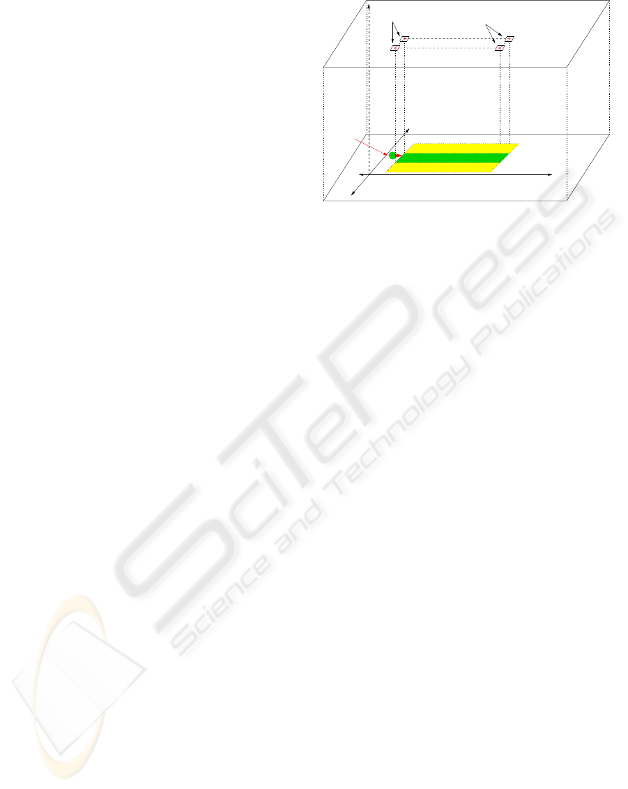
In order to compute the estimated relative position
of the mobile robot using an RFID system, RFID tags
are arranged in a fixed pattern on the ceiling, for in-
stance, as depicted in Figure 1. An RFID reader is
mounted on the mobile robot and four tags are at-
tached to the ceiling. The points P1, P2, P3, and
P4 define the orthogonal projections of the four tags
on the ground. The robot is supposed to navigate
along the virtual desired path defined by the projec-
tion points.
3.1 Technical Background of an RFID
System
We now review the fundamental properties of a com-
mercially available RFID system in the market. RFID
is a type of automatic object identification system.
The principle of an RFID system consists of storing
an individual static binary code to every object that
need to be identified and the automatic seizing of in-
formation via radio waves. An RFID system is mainly
composed of three main components: a tag, an RFID
reader, and a host computer (Peris-Lopez et al., 2006).
Y
Z
Tag 2
Tag 1 Tag 3
Tag 4
Source tags
Destination tags
P1
P3
P2
−Y
Ceiling
Ground
P4
−X X
Mobile robot
Right of path
Left of path
In path
Figure 1: Relative position system setup.
The tag is composed of a microchip with some ba-
sic storage capabilities, and a coupling element such
as antenna coil for communication. An RFID reader
is generally composed of an RF module, a control
unit, and a coupling element to interrogate electronic
tags via RF communications. The purpose of the host
computer is to execute a special purpose software in
order to store, process, and analyze the data acquired
by the reader. In the current work, an RFID reader is
interfaced with the robot’s central processing unit to
perform further processing of tags’ information.
3.2 Relative Positioning Technique
As mentioned above, most of the existing RFID sys-
tems available in the market provide only static in-
formation which limit its applicability in many real-
world proximity-based RFID applications. In the cur-
rent work, we propose a navigation strategy for guid-
ing a mobile robot in an indoor environment using a
customized RFID tag architecture that allows to en-
code some dynamic information along with its exist-
ing static ID. Figure 2 depicts a customized model of
an RFID tag employed in the current research. The
tag receives an RF signal transmitted by the reader
which is then rectified to get its RSS value. In the
present RFID system, the tag has some processing
capability to convert the RSS value into an 8-bit bi-
nary code. As can be seen in figure 2, the RSS mea-
surement of the RFID reader query is embedded with
the tag’s existing static binary ID (16-bit in this case)
which is then backscattered to the RFID reader. It is
important to articulate the fact that the reader archi-
tecture of the proposed RFID system requires no cus-
tomization as it would read the 24-bit (16-bit tag-ID +
8-bit RSS) frame in exactly the same way it normally
reads tag-IDs. The RFID reader extracts the frame
backscattered by the tag which is then passed to the
TOWARDS A COMPUTATIONALLY EFFICIENT RELATIVE POSITIONING SYSTEM FOR INDOOR
ENVIRONMENTS - An RFID Approach
333
Communication
Other Devices
Memory
RFID tag
Tag’s customization
Electromagnetic wave
Energy
Wireless
DC Power Generator
Frame (24 bits)
16 bit
Tag ID
Received signal strength (dBm)
8 bit
RFIDrReader
Interface
Transceiver
Figure 2: Proposed RFID architecture.
processing element on the robot’s board to decode it
into a tag-ID and an RSS value. The RSS values are
used to approximate the relative position of the mo-
bile robot with respect to its desired path.
We now explain how the relative position of the
robot can be approximated by incorporating tags’
RSS values in an indoor environment. In this work,
the robot is presented with a set of four tag-IDs,
S = {1, 2, 3, 4}, for instance, where tags with IDs 1
and 2 define the source (starting) point, and the tags
with IDs 3 and 4 define the destination, respectively.
Note that the tag coordinates in the world coordinate
system are not necessarily known. The robot com-
putes its position with respect to the desired path by
extracting and decoding the frames backscattered by
fours tags defining the path. The RSS values are then
used to model the relative position which is defined
by
∆RSS = (RSS
1
+ RSS
3
) − (RSS
2
+ RSS
4
) , (1)
where the RSS
i
with 1 ≤ i ≤ 4 represents the average
RSS value associated with tag i. The RSS samples
received from each tag are passed to an M-point mov-
ing average filter for better estimation. The filter is
modeled as
RSS
i
=
1
M
M
∑
j=1
RSS
ji
∀i ∈ S , (2)
where RSS
ji
is the j
th
RSS value at tag i. The signif-
icance of ∆RSS is the amount of robot’s divergence
from its desired path. Ideally, ∆RSS is closest to nil
when the robot is on the right track. It diverges from
zero as the robot moves drifts away from its path. The
sign of ∆RSS then depends on the side of the path the
robot is located.
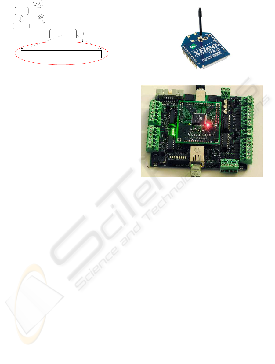
(a)
(b)
Figure 3: RFID system (a) RF module used to emulate an
RFID tag
4
and (b) Make controller board used to emulate
an RFID reader
2
.
4 RFID SYSTEM
IMPLEMENTATION
The proposed RFID system is emulated using the
XBee Pro Modules
1
shown in Figure 3(a) as an in-
tegrated RF solution. The modules include MC13193
RF chip by freescale, which is compliant to the IEEE
802.15.4 norm (Graefenstein and Bouzouraa, 2008).
One of the XBee Pro modules is attached to the Make
Controller (MC) board
2
(figure 3(b)) to emulate a
commercial RFID reader. The MC board secures the
communication between the emulated RFID reader
and the robot.
In order to obtain an RSS value from a tag i,
1 ≤ i ≤ 4, the reader broadcasts a message with its
own static address. The tags are simply configured to
reply to the reader’s query with their individual binary
frames. As mentioned above, each tag’s frame con-
sists of its 16-bit static address and 8-bit RSS value.
1
http://www.digi.com/products/wireless/point-multipoint/xbee-pro-
series1-module.jsp, http://www.digi.com
2
http://www.makingthings.com/, http://www.makingthings.com
ICINCO 2009 - 6th International Conference on Informatics in Control, Automation and Robotics
334
The reader simply extracts and decodes the frames in
order to get the tag’s ID and the corresponding RSS
value and then passes them along to the mobile robot
for further processing.
5 EXPERIMENTAL RESULTS
The purpose of this section is to provide details on the
experimental evaluation of the proposed relative posi-
tioning system using the emulated customized RFID
tag architecture. The performance is evaluated using
real data in a research laboratory that reflects a typical
indoor operating environment.
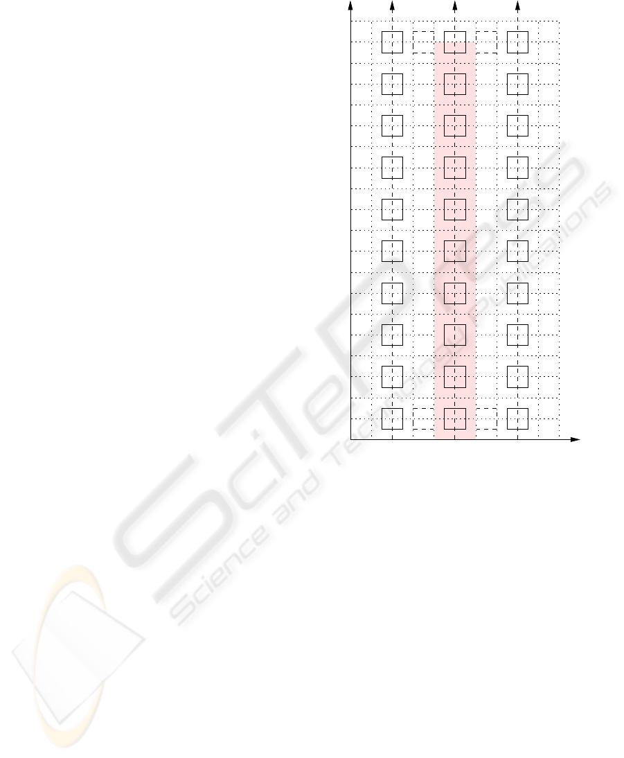
The experiments of the proposed RFID-based
RPS were carried out at discrete points distributed
over approximately 3 ×6 ×2 m test area of a research
laboratory with four tags attached on four different
posts (≈ 2 m high). The test area is divided into uni-
form square grids of 30 × 30 cm
2
. The layout of the
test environment is depicted in Figure 4. The orthog-
onal projection points of the four tags on the ground
are what we call herein S1 and S2 for source, and D1
and D2 for destination. The desired trajectory is the
line linking the midpoints of the lines connecting S1
and S2, and D1 and D2, respectively.
To test the proposed RPS concept, ∆RSS is com-
puted at 30 different locations: 10 on the desired robot
trajectory (shaded area in figure 4), 10 on its left, and
10 on its right. The results are revealed in Table 1.
Each RSS value (in dB) is the output of an 8-point
moving average filter as defined in (2). It can be seen
from Table 1 that the data corresponding to the left of
the path is globally larger than zero, which confirms
that the robot is indeed out of its desired trajectory.
However, the same conclusion cannot be generalized
on the data collected on the right of the path since it
is generally close to that collected on the path. This
may be due to several reasons. The side test locations
are only 0.6 m off the path, which is an insignificant
distance compared to the height of the emulated RFID
tags (2 m). In other words, the distance between S1
and robot location 5, for instance, is not significantly
different from that between S1 and location 5R. This
is a main source of ambiguity which contributes to
this lack of precision. We believe that ∆RSS would
be more distinguishable across the three regions if the
side locations were at least 3 m off the path. This
threshold highly depends on the RF signal attenuation
with the distance traveled. It is also important to in-
vestigate better noise filtering techniques to filter the
severe noise experienced at the testing scene. The lab
at which the experiments were conducted contain an
abundance of metal cabinets and obstacles of various
path
1L
2L
3L
4L
6L
7L
8L
9L
5L
1R
2R
3R
4R
5R
6R
7R
8R
9R
S1S2
D1D210L 10R
Left side
path
Right side
path
Y(m)
0.3 0.6 0.9 1.2 1.5 1.8 2.1 2.4 2.7 3.00
6.0
5.7
5.4
5.1
4.8
4.5
4.2
3.9
3.3
3.0
2.7
2.4
2.1
1.8
1.5
1.2
0.9
0.6
0.3
3.6
X (m)
7
8
9
10
6
5
4
3
2
1
Desired
Figure 4: Experimental setup of the proposed navigation
system.
materials. Such a choice was made on purpose to test
worst condition scenarios.
6 CONCLUSIONS
The rising prominence of location estimation in many
real-world applications necessitates the development
of an appropriate positioning system in an indoor en-
vironment. Due to the ubiquity of such localization
systems, the proposed RFID-based localization sys-
tem provides a suitable and a cost-effective solution
for devising such systems. In this paper, we have ex-
amined the problem of relative positioning system us-
ing RSS measurements of a modified RFID tag archi-
tecture and have proposed a novel guidance principle
for a mobile robot to navigate in an indoor environ-
ment based on the strength of the RF signal transmit-
ted by the RFID reader. As the first contribution of the
TOWARDS A COMPUTATIONALLY EFFICIENT RELATIVE POSITIONING SYSTEM FOR INDOOR
ENVIRONMENTS - An RFID Approach
335

Table 1: Performance of the relative positioning system.
Position S1 S2 D1 D2 ∆RSS
1L 41 41 58 53 5
2L 44 44 58 54 4
3L 47 46 59 54 6
4L 50 45 55 54 6
5L 50 48 50 50 2
6L 51 52 49 46 2
7L 53 57 53 40 9
8L 53 58 50 41 4
9L 54 55 48 42 5
10L 63 60 43 38 8
Average 5.1
Std. Dev. 2.3
1 28 36 53 56 -11
2 42 38 54 57 1
3 44 45 50 50 -1
4 47 46 54 56 -1
5 50 46 52 54 2
6 51 52 49 49 -1
7 52 54 49 42 5
8 55 53 41 49 -6
9 57 56 38 44 -5
10 57 61 39 36 -1
Average -1.8
Std. Dev. 4.5
1R 37 42 62 57 0
2R 45 43 58 54 6
3R 43 47 56 51 1
4R 55 47 58 53 13
5R 54 51 49 49 3
6R 54 54 52 50 2
7R 56 57 49 48 0
8R 55 54 44 47 -2
9R 53 53 39 45 -6
10R 57 59 37 42 -7
Average 1.0
Std. Dev. 5.8
current work, spatial relative positioning is proposed
to address the variability of tags’ RSS patterns over
the workspace. The proposed method was evaluated
using real data from a typical office environment. Al-
though the preliminary results reported in the present
manuscript reveal what might be a promising indoor
RPS method, more effort needs to be done to bring
the proposed technique to a more mature stage.
REFERENCES
Desouza, G. N. and Kak, A. C. (2002). Vision for mobile
robot navigation: a survey. IEEE Transactions on Pat-
tern Analysis and Machine Intelligence, 24(2):237–
67.
D’Orazio, T., Ianigro, M., Stella, E., Lovergine, F. P.,
and Distante, A. (1993). Mobile robot navigation
by multi-sensory integration. In Proceedings of 1993
IEEE International Conference on Robotics and Au-
tomation ICRA, pages 373–9, Atlanta, GA, USA.
Graefenstein, J. and Bouzouraa, M. E. (2008). Robust
method for outdoor localization of a mobile robot us-
ing received signal strength in low power wireless net-
works. In 2008 IEEE International Conference on
Robotics and Automation. The Half-Day Workshop
on: Towards Autonomous Agriculture of Tomorrow,
pages 33–8, Pasadena, CA, USA.
Hahnel, D., Burgard, W., Fox, D., Fishkin, K., and Phili-
pose, M. (2004). Mapping and localization with RFID
technology. In Proceedings - IEEE ICRA, number 1,
pages 1015–1020, New Orleans, LA, United States.
Kim, M. and Chong, N. Y. (2009). Direction sensing
RFID reader for mobile robot navigation. IEEE
Transactions on Automation Science and Engineer-
ing, 6(1):44–54.
Kulyukin, V., Gharpure, C., Nicholson, J., and Pavithran, S.
(2004). RFID in robot-assisted indoor navigation for
the visually impaired. In 2004 IEEE/RSJ IROS, pages
1979–84, Sendai, Japan.
Lanzisera, S., Lin, D. T., and Pister, K. S. J. (2006). RF
time of flight ranging for wireless sensor network lo-
calization. In Proceedings of the Fourth Workshop
on Intelligent Solutions in Embedded Systems, WISES
2006, pages 165–176, Vienna, Austria.
Lin, C.-C. and Lal Tummala, R. (1997). Mobile robot nav-
igation using artificial landmarks. Journal of Robotic
Systems, 14(2):93–106.
Milella, A., Vanadia, P., Cicirelli, G., and Distante, A.
(2007). RFID-based environment mapping for au-
tonomous mobile robot applications. In
IEEE/ASME
International Conference on Advanced Intelligent
Mechatronics, AIM, Zurich, Switzerland.
Nasri, N., Kachouri, N., Samet, M., and Andrieux, L.
(2008). Radio Frequency IDentification (RFID):
Working, design considerations and modelling of an-
tenna. In 2008 5th International Multi-Conference on
Systems, Signals and Devices, SSD’08, Amman, Jor-
dan.
Peris-Lopez, P., Hernandez-Castro, J. C., Estevez-Tapiador,
J. M., and Ribagorda, A. (2006). RFID systems: a sur-
vey on security threats and proposed solutions. In Per-
sonal Wireless Communications. IFIP TC6 11th Inter-
national Conference, PWC 2006. Proceedings, pages
159–70, Albacete, Spain.
Yi, S.-Y. and Choi, B.-W. (2004). Autonomous navigation
of indoor mobile robots using a global ultrasonic sys-
tem. Robotica, 22:369–74.
Youssef, M. (2004). The Horus WLAN location determi-
nation system. PhD thesis, University of Maryland,
Maryland.
ICINCO 2009 - 6th International Conference on Informatics in Control, Automation and Robotics
336
