
HIGH-RESOLUTION IMAGE GENERATION USING WARPING
TRANSFORMATIONS
Gabriel Scarmana
Department of Main Roads, Queensland Government, Australia
Keywords: Warping transformation, Digital image enhancement, Sub-pixel registration.
Abstract: In recent years the emphasis for applications of 3D modelling has shifted from measurement to
visualization. New communication and visualization technologies have created an important demand for
photo-realistic content in 3D real-time animations, interactive fly-overs and walk-arounds, panoramic
images, visualizations and simulations based on real-world data.
These image-based approaches require acquisition procedures that are simple and flexible with the use of
consumer photo- or video-cameras. Ideally the user should be able to move freely while acquiring the
images with any device ranging from a mobile phone to a video camera. In this context, a device
independent algorithm for the estimation of an enhanced resolution image from multiple low-resolution and
distorted compressed video images having arbitrary views is proposed in this paper.
This process of spatial image enhancement is demonstrated here in a controlled scenario whereby the
different views of the same scene are warped, firstly, to a common orientation so that a rigorous least
squares area-based matching technique can then compute the registration parameters needed for their
accurate combination. The sequence is acquired using a digital camera in video mode, which samples the
image of a static scene from different angles.
The warping is an iterative process relying on manual intervention and is used here to compensate for the
different range of scales and orientations of the low-resolution imagery. Once this imagery is brought into
registration and complies with pre-established image correlation criteria, they are combined to recover a
high-resolution composite. Although the quality and resolution of the sensor arrays used to capture digital
data continue to evolve, it is important that any technique used to enhance spatial resolution must be device
independent, thus capable of using input from not only low-resolution images but also from higher
resolution devices.
1 INTRODUCTION
Off-the-shelf digital video cameras employ low-
resolution sensors that sub-sample the original
image sequence. The imagery obtained from video
sequences is often compressed in a lossy manner,
such as by the MPEG (Moving Picture Expert
Group) protocol, in order to reduce the storage
requirements (Russ, 2007).
Lossy compression means that data is lost during
compression so the quality after decoding is less
than the original picture. Lossy compression
protocols also introduce several distortions that can
complicate the enhancement problem. For example,
most compression algorithms divide the original
image into blocks that are processed independently,
thus creating problems of continuity between blocks
after decompression (Farsiu et al. 2004
).
Moreover, at high compression ratios (>15:1, as
suggested in (Reed, 2005 and Bovik, 2005)), the
boundaries between the blocks become visible and
lead to ‘‘blocking’’ artefacts. The blocking effect is
especially obvious in flat areas of an image. In areas
with lots of detail, artefacts referred to as ringing or
mosquito noise also become noticeable.
Yet, video sequences contain a large overlap
between successive frames, and regions in the scene
of interest are sampled in several images and often
from different perspective. This multiple sampling
can be used to reconstruct imagery with a higher
spatial resolution if the images in the sequence are
accurately registered, one to another (Vandewalle et
al, 2005). The result is then similar to using a high-
resolution camera.
49
Scarmana G. (2009).
HIGH-RESOLUTION IMAGE GENERATION USING WARPING TRANSFORMATIONS.
In Proceedings of the International Conference on Signal Processing and Multimedia Applications, pages 49-56
DOI: 10.5220/0002225900490056
Copyright
c
SciTePress

On the other hand, video frames cannot be
related through global transformations due to
arbitrary pixel movements between the images. As a
result, images of the same scene taken from slightly
different angles and distances to the same object
introduce geometric distortions (i.e., parallel lines
are not parallel, angles are not correct, distances
appear too long or too short, etc.).
Hence, the arbitrary and distorted views of the
scene of interest must first be iteratively warped to a
common orientation before an accurate registration
procedure can compute the parameters needed for a
correct sub-pixel registration.
The least squares area based registration method
employed here provides for an efficient and reliable
scheme designed to match or align low-resolution
images of the same scene. The methodology is
capable of achieving sub-pixel accuracies of
approximately 0.1 pixels. This technique can also
overcome difficulties arising from slight radiometric
differences, that is, slight differences in grey scale
levels due to varying illumination conditions in the
images being matched.
Once all the low-resolution images are brought
into sub-pixel registration and comply with pre-
established image correlation criteria, the images are
combined to recover the desired high-resolution
composite. In addition to improving the spatial
resolution, the method may also attenuate artefacts
caused by lossy compression protocols.
In summary, the basic steps of the proposed
image enhancement technique are divided into three
main tasks:
• Warping transformations
• Image registration to a sub-pixel level and
• Reconstruction via image mapping on a higher
resolution and uniformly distributed grid.
Details of how these three problems are solved
are presented in the following sections.
2 WARPING AND RESAMPLING
Image warping is a geometric transformation that
maps all positions from one image plane to positions
in a second plane. It is used to solve many digital
image-processing problems such as removing optical
distortions introduced by a camera and a particular
viewing perspective or registering an image with a
map.
Warping is closely related to the popular image
metamorphosis, or morphing technique, and is used
extensively to produce special effects in the field of
computer graphics and the entertainment industry.
In most iterative warping systems, the user
specifies the warp in some very general way, for
example by moving grid lines or by specifying
point-to-point correspondence or control points
(Zitova et. al., 2004). A computerised system then
automatically interpolates these geometric
specifications.
Amongst the diverse warping models available,
the use of generic polynomials is often considered
appropriate due to the simplicity of application and
accuracy requirements (Russ, 2007). Polynomials
are widely used as an approximating function in all
types of data analysis.
The level of detail in the data that can be
approximated depends directly on the order of the
polynomial. The polynomial models are determined
by first defining a set of control points (CPs) on each
image (source and target) which correspond to pixel
locations that must align together. This is necessary
to constrain the polynomial coefficients. Ideally the
control points should have the following
characteristics:
• High contrast in all images of interest
• Small feature size
• Unchanging over time
• Coplanar
Choosing the optimal warping procedure is
problematic, with the approach taken here to use a
warping process to stretch and pull the source
images about defined CPs. This yields images that
conform to particular geometric and scene
requirements. The pixels are then repositioned, by
way of interpolation techniques, from their original
locations in the data array, into a specified reference
grid dictated by the selected CPs.
Finding corresponding CPs in an image is the
most tedious aspect of warping transformations,
since it usually requires manual intervention to
determine their optimal location. Determining
optimal CPs automatically (i.e. without human
participation) is desirable and is a subject of further
research by the author.
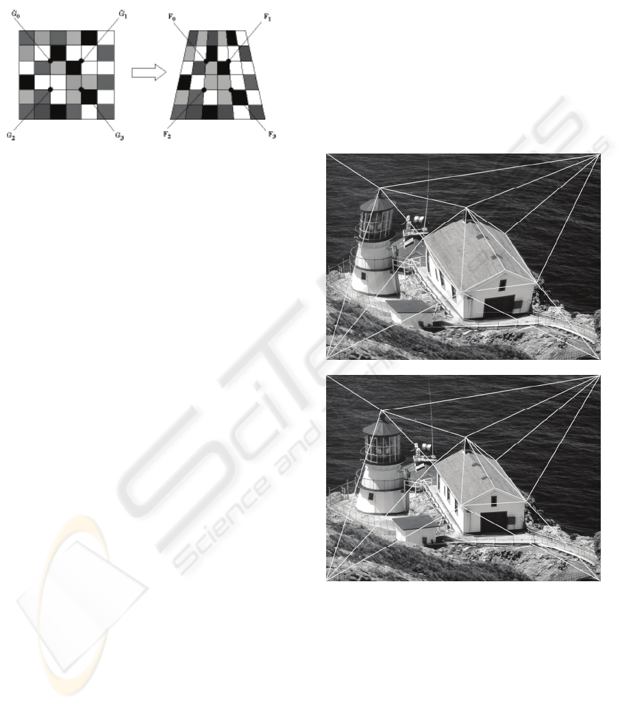
An illustration of the warping process used in the
experimental part of the proposed image
enhancement process is given in Figure 1, showing a
distorted grid on the right that has undergone a
geometric transformation from an original grid (on
the left) making it appear trapezoidal in shape.
Located in the centre of the rectangular grid are four
points that can be related to the corresponding points
in the distorted grid
SIGMAP 2009 - International Conference on Signal Processing and Multimedia Applications
50
The geometric association between these eight
points describes the geometric distortion between
the trapezoidal and the rectangular grids. It is also
due to this geometric relationship that these eight
points are referred to as the CPs.
G
0
→F
0
; G
1
→F
1
; G
2
→F
2
; G
2
→F
2
Figure 1: An example of a trapezoidal distortion of a
rectangular grid.
If G(r, s) describes the original grid and F(x, y)
the trapezoidal grid, then the coordinates of these
CPs can be related through a set of bilinear
equations as:
x
= a
1
r + a
2
s
+ a
3
rs + a
4
(1)
y = a
5
r + a
6
s
+ a
7
rs + a
8
(2)
where the coefficients a
i
(i = 1…8) determine the
actual geometric relationship between the original
and distorted grids.
Given that there are eight unknown coefficients
and four corresponding CPs on each grid, then a
unique and simple solution is possible. Equations (1)
and (2) can produce only linear geometric
transformations, so to correct for arbitrary and
complex curvatures or distortions, higher order
terms may be needed. Typically, equations (1) and
(2) can be expanded to include higher order terms or
to construct spline models (Gonzalez, 2007).
The concept of removing the geometric
distortions from a grid can be easily transferred to
that of a digital image. Indeed, the CPs in the grid
example above could be considered as relating four
pixels in the undistorted image to four pixels in the
geometrically distorted image.
The approach used in this study is to use many
closely spaced CPs and model the geometric
distortion within the region defined by those points
as linear. Each set of CPs corrects the pixels just
within the region enclosed by the control points.
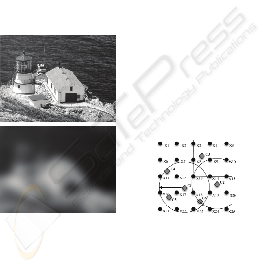
The results in Figure 2 were achieved using this
process.
The disadvantage of using this method is the
quantity of CPs needed for very complex geometric
distortions. In implementing equations (1) and (2),
every pixel in the restored image G(r,s) is obtained
by using the mapping coordinates x, y in the
geometrically distorted image F(x,y) and the CPs
associated with that pixel.
For two given images (distorted and reference)
of the same scene, the warping process will usually
need to be iterated until the selected distorted image
clearly resembles the selected target or reference
image. Tests by the author show the warping process
is satisfactory when the correlation coefficient
between the two registered images is greater or
equal to 0.999.
Figure 2: A distorted image (a) is warped to create the
image in (b) where proportions are rectified.
Figure 2 shows the results of warping or
transforming the image in Figure 2(a) into the image
in Figure 2(b) after 14 warping attempts. 45 CPs
were used in this process. By way of illustration,
only a few of the total number of CPs are shown in
the figure.
The use of contiguous triangles between three
control points and with linear polynomial
transformations in each triangle usually eliminates
HIGH-RESOLUTION IMAGE GENERATION USING WARPING TRANSFORMATIONS
51

the discontinuities of the boundaries. The distortion
is then modelled by a piecewise set of planes,
similar to a faceted surface.
When using a network of CPs, it may not be
necessary to warp all the triangle areas with the
same number of iterations. For instance, intuitively it
could be expected that the ocean areas in Figure 2,
which are smooth with low detail features, would
require fewer warping iterations than the building
regions.
Since the (x,y) pixel coordinates of the warped
image will no longer be integer values, new integer
pixels must be estimated by an interpolation process.
There exist many interpolation methods, the most
common being the nearest neighbour, bilinear, cubic
convolution and splines techniques.
The spatial and local interpolation technique
considered here was the nearest neighbour
interpolation. Although bilinear interpolation and
cubic convolution may yield more visually pleasing
results the nearest neighbour approach is generally
used when radiometric fidelity is at a premium
(Russ, 2007).
Once all the low-resolution images are processed
and warped to a common orientation using the
methodology described above, the next step is to
register or match all the low resolution images to a
common reference frame and thereby determine the
value of the sub-pixels shifts existing (if any) among
them.
3 IMAGE REGISTRATION
In an idealised scene registration, two different
images of the same object are assumed to be
essentially identical except for an x and y shift. In
practice, with distorted and multi-temporal video
frames, the two images will generally exhibit
substantial differences beyond this assumption.
These differences can be classified as:
• Intensity differences, - e.g. the images are taken
at different times or under different lighting
conditions;
• Structural differences, - e.g. between the taking
of the two images the common objects may have
altered; and
• Geometric differences, - e.g. the motion of the
camera may cause geometric differences such as
rotation, aspect and scale in the object.
Even though two images may both be of the
same scene, these differences of intensity, structure,
and geometry will often be sufficient to produce
erroneous registrations. If the differences of intensity
and structures are very small, the reference image
can be thought of as an exact map of the object
scene and scene matching can be characterised as
map matching.
On the other hand, when the differences between
two images are large, the reference information may
no longer be a map but somewhat like directions
given to a lost tourist: ‘Turn left at the set of lights,
follow the road past the church and then turn right
after the park’. With this knowledge, the tourist can
effectively perform the scene-matching function and
find his way to his intended destination.
Analogously, when there is a considerable
difference between two images, simple matching
algorithms will not work and so some iterative
warping of one image relative to the other must take
place before the images can appear similar and be
combined into a higher resolution composite.
The registration problem can be stated as finding
the transformation T (the warping transform) that,
when applied to one image F(x, y), will ultimately
bring the object detail into registration with the
corresponding detail in another image G(r, s), such
that:
T
* F(
x
,y) = G(r,s) (3)
where the symbol = means equivalence of object
detail.
The result of applying the warping
transformation T to all the low-resolution images is
used to carry out a preliminary alignment of all the
low-resolution images. The alignment assumes that
there is only a global translation among the images
and, as a preliminary step, this alignment is carried
out within the integer range. This initial step is
referred to as the pixel shift estimator and is based
on normalized cross-correlation techniques.
After the low-resolution images are aligned
within a pixel, the second step is to compute the real
fractional shift between each image. The method for
estimating this fractional shift is based on Taylor
series and can achieve sub-pixel accuracies of
approximately 0.1 pixels. The reader is referred to
Pilgrim (1991) for the theory and formulation behind
this methodology.
For a correct detection of the shifts or offsets
between two images, the images must contain some
features that make it possible to register or match
them.
Very sharp edges and small details are most
affected by aliasing, so they are not reliable to be
used to estimate these shifts. Uniform areas are
useless, since they are translation invariant
SIGMAP 2009 - International Conference on Signal Processing and Multimedia Applications
52
(Hendriks et al. 1999). The best features are slow
transitions between two areas of grey values as these
areas are generally unaffected by aliasing. Such
portions of an image need not be detected
specifically, although their presence is very
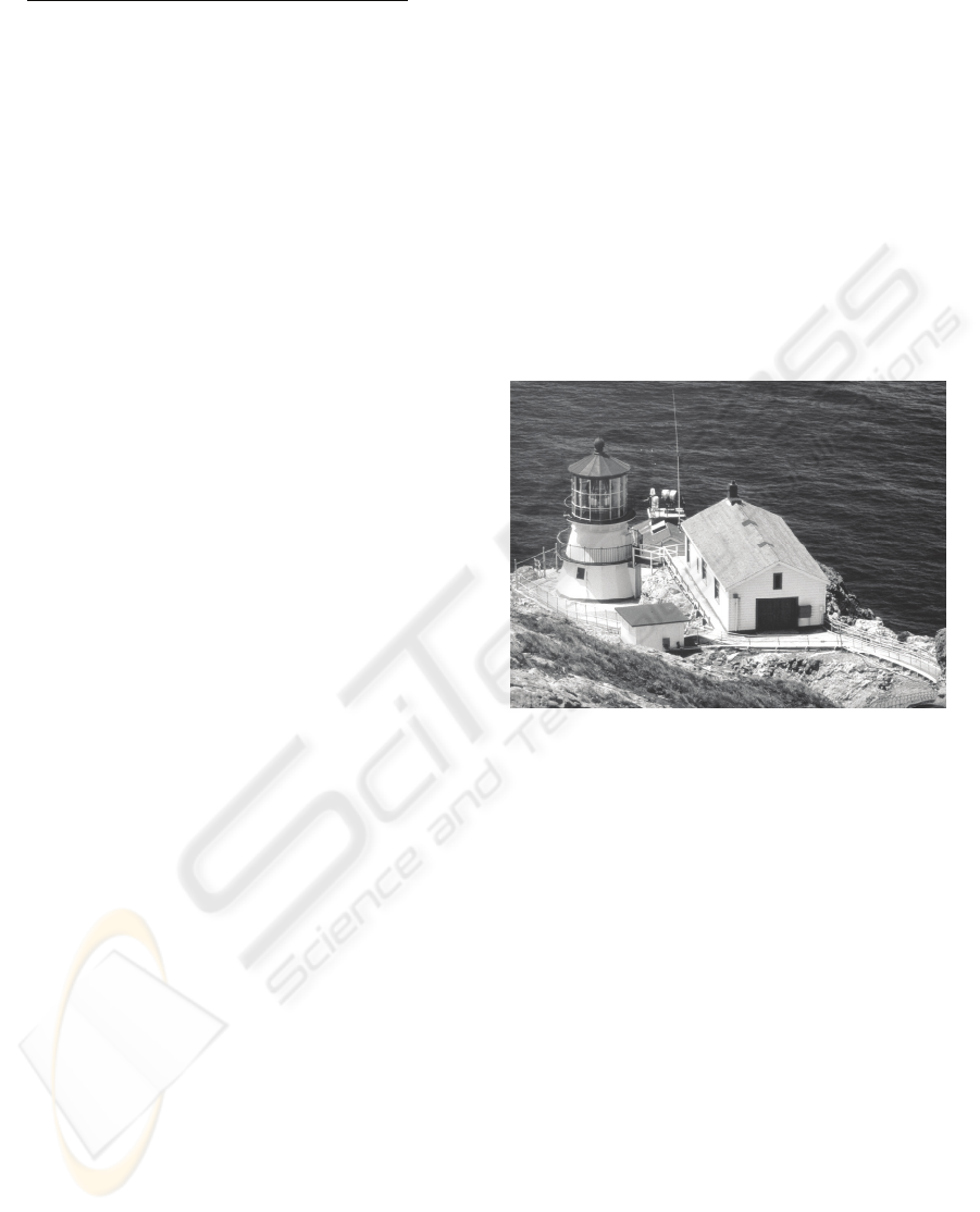
important for an accurate result. Hence, before a
given sequence of images of the same scene is
registered, a low-pass filter may be applied
uniformly to each image. The purpose of a low-pass
filter, as shown in Figure 3, is to smooth:
• Sharp edges and small details
• Sudden changes of intensity values and
• The distortions created by the compression
process.
Figure 3: The lighthouse (top) and after applying a low-
pass filter (Gaussian, 18 pixels radius, below).
The motion estimator (registration procedure)
adopted in this research determines the x- and y-
shifts and rotations between any two images, but
what is really required is the relative positions of a
sequence of images. By calculating the shifts with
respect to a single reference image, only one
realization of the relative positions is obtained. By
repeating the procedure for another reference image,
a second estimate for the relative positions is made.
Continuing to repeat this process for all images
in the sequence, a better estimate of the relative
shifts, image to image, can be found. The statistical
measure used to determine the ‘best’ possible value
for all possible combinations of the motion vectors
between a set of shifted low-resolution images is the
vector median.
If the vector mean was taken instead of the
median, then the final motion vector would be an
entirely new vector, and not one of the vectors
originally estimated. In addition, the mean is less
robust than the median if outliers are present
(Spiegel et al., 1999).
4 IMAGE RECONSTRUCTION
Once all the low-resolution images have been
warped and registered to a sub-pixel level, they are
projected or mapped on a uniformly spaced high-
resolution grid (see Figure 4). A weighted arithmetic
mean associates each known pixel of the low-
resolution images to the high-resolution pixels.
For example, in Figure 4 the low-resolution pixel
C1 can be related to the pixels of the high-resolution
grid by way of Equation 4. In Figure 4 the Xi
(i=1…25) represent the high-resolution pixels
whereas the Cj, (j=1…6) are the low-resolution
pixel.
Figure 4: An idealized image enhancement set-up.
After C1 is related to the high-resolution
coordinate system, the process moves on to the next
low-resolution data pixel (i.e. C2) where another
equation is constructed. This sequence of equations
may be thought of as “observation equations” where
the unknowns are the values of the high-resolution
pixels (Xi). These linear equations can be solved by
traditional least squares techniques (for example,
Fryer et al., 2001).
R
HIGH-RESOLUTION IMAGE GENERATION USING WARPING TRANSFORMATIONS
53
C1=
w
12
x
12
+w
13
x
13
+w
16
x
16
+w
17
x
17
+…+w
23
x
23
(4)
w
12
+w
13
+w
16
+w
17
…+w
23
The weights (w) are defined by the inverse of the
distance that separates the low-resolution pixel from
the unknown high-resolution pixels that fall within a
circle of constant radius (R). This circle is centred
on each low-resolution pixel as shown in Figure 4.
The dimension of the radius R depends on the
magnification factor required. As a general rule, if
the magnification factor is chosen to be equal to 2
then the minimum radius for the circle required to
search all the high-resolution pixels is 2√2. On the
other hand, if the chosen magnification factor is n
then the minimum search radius is taken as n√n, etc.
The example in Figure 4 relates to a
magnification factor of 3 where the final high-
resolution composite will have 3 times more pixel
values in each coordinate direction than any of the
low-resolution images. To comply with sampling
theory, R must ensure that an overlapping occurs
between the circles, as it is important that each of the
unknown high-resolution pixels appear at least twice
in different observation equations.
Note that there will be an equation for each low-
resolution pixel, being the number of equations at
least equal or greater than the number of desired
high-resolution pixels in the final enhanced
composite. Hence, when (say) five suitably
overlapping images each of modest size 500x500 are
considered, it becomes apparent that 500x500x5 =
1.25 million observation equations could be formed.
If a magnification factor of 2 is chosen, then the
resultant resolution enhanced image will exceed in
size 1000 x 1000 thus requiring the solution of 1
million linear simultaneous equations.
Although more computationally expensive, as
compared to direct interpolation methods, the
process minimizes the error variance and sets the
mean of the prediction errors to zero so that there are
no over- or under-estimates. An important feature of
this “reverse mapping” process is that it also gives
an estimation of the error at each computed point,
thus providing a measure of confidence for the
accuracy and precision of each high-resolution pixel
of the enhanced composite.
5 THE TEST IMAGES
To explore the performance of the image
enhancement algorithm using images requiring
warping, a sequence of dynamic low-resolution
images of a lighthouse was taken with a digital
camera in video mode. They were taken under
similar lighting conditions, but each with slightly
different scale, views and aspect.
These high-resolution images were then warped
and subsequently matched to determine the sub-
pixel shifts existing amongst them. The shifts were
then used to map the low-resolution as described in
the previous section and used to form the
observation equations required to construct a high-
resolution composite of the same scene.
A section of 640x480 pixels depicting the
lighthouse was cropped from an image of a large
poster taken at a resolution of 2560X1920 using a
digital camera in still mode for a JPEG compression
ratio of approximately 6 (as illustrated in Figure 5).
This image section was considered as the true image
in the following test.
Figure 5: The original true image of the lighthouse
(640x480).
The objective was to investigate how well a
resolution-enhanced image could be recovered from
40 MPEG compressed image sections of the same
scene extracted from the same camera in video
mode. The video sequence was taken at a resolution
of 640x480 and by moving the camera so as to
sample the object of interest from slightly different
angles and distances.
The 40 low-resolution images were cropped to
be approximately of dimensions 160x120 pixels so
as to depict the same scene. Figure 6 shows one of
these low-resolution images.
For statistical purposes care was taken to obtain
one of these low-resolution images (reference
image) from exactly the same distance and
perspective view as the true image. This was
attained by fixing the camera to a tripod.
Since there were 40 low-resolution images, 39
different sub-pixel shifts in x and y could be defined
for each image with respect to each of the others. All
the low-resolution images were manually warped
SIGMAP 2009 - International Conference on Signal Processing and Multimedia Applications
54
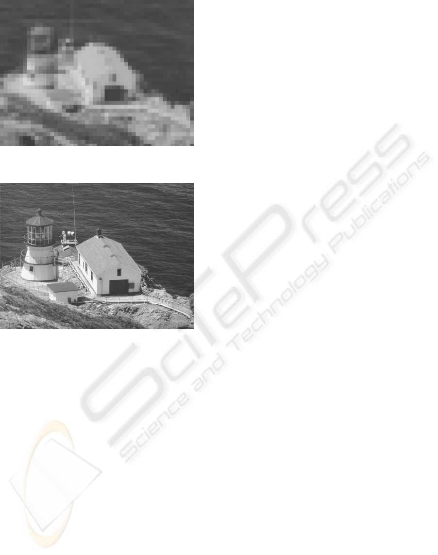
Figure 6: One example of the 40 low-resolution images
(160x120).
Figure 7: The high-resolution composite (640x480) as
constructed using 40 low-resolution distorted images
(160x120).
as described in section 4 and aligned with the
reference image. This tedious operation involved an
average of 40 control points per image mostly
distributed with the building areas of the image.
An enhanced image was then computed for a
magnification factor of 4, and using the shifts as
determined by the vector median of all possible
combinations. Figure 7 shows the final enhanced
composite.
The root mean square (r.m.s.) of the difference
between the reconstructed composite shown in
Figure 7 and the full resolution image or true image
in Figure 5 was computed as ±5.22 grey-scale values
with a correlation coefficient of 0.99968.
6 NUMBER OF IMAGES
The required number of low-resolution images
generally depends on the distribution of the shifts, as
well as on the signal-to-noise ratio, and the amount
of noise present. For instance, to minimise the
influence of noise it is important that the distribution
of the shifts between the low-resolution images be as
complete as possible.
The reconstruction of a higher resolution image
with the minimum number of low-resolution images
is possible, but it should not be expected to always
achieve a high accuracy, especially for higher
magnification factors (>5). High magnification
factors require large numbers of low resolution
images, meaning that these low resolution images
must be relatively close to one another, that is,
relatively small offsets.
The accuracy of detecting those offsets will
clearly affect the accuracy of the final composite
image as the uncertainty in an offset’s determination
may be of the same magnitude as the offset itself
(Scarmana G. and Fryer J., 2006).
7 CONCLUSIONS
A procedure for reconstructing a high-resolution
image from a sequence of low-resolution, distorted
and compressed image sequences has been
described.
The method makes use of an image warping
technique to align or register the low-resolution and
distorted images to a common reference framework.
The results for a sequence of 40 video images of a
static image that were manually warped in order to
be compatible for the enhancement algorithm,
showed an r.m.s. comparison with a higher
resolution “true” image of +/- 5.22 grey scale values.
Refinements to the proposed methodology are
presently being explored in an effort to further
enhance the spatial and brightness resolution and
thereby expand the range of applications that may
benefit from using the proposed technique for image
enhancement of small dynamic objects. Small is
defined such that the total number of pixels on the
border of the objects is significant, as compared to
the amount of pixels within the object.
This is typical of objects of interest which appear
small if compared to the field of view of the images
and the relatively large distance between the image
sensor and the scene (i.e., faces in security cameras).
The author is also currently investigating the
possibility of adapting this enhancement process to a
more generalised scheme whereby both sensor and
object are dynamic and the illumination is non-
uniform. A considerable amount of manual input
was required to select control points for the warping
HIGH-RESOLUTION IMAGE GENERATION USING WARPING TRANSFORMATIONS
55

procedure, and although there is an argument for
manual input, investigations into automating the
warping process with the automatic detection of
specific landmarks on the images is under
consideration.
The image enhancement algorithm described in
this paper expands the possibilities for using either
low-cost digital still cameras, video camcorders or
even the new generation of videophones to obtain
suitable imagery for numerous applications in
security, forensic measurement, architecture,
archaeology and other non-traditional areas of
digital image processing.
REFERENCES
Bovik .A., 2005. Handbook of Image and Video
Processing. Elsevier Academic press.
Farsiu S., Robinson D., Elad M., and Milanfar P., 2004.
Advances and Challenges in Super-Resolution
International Journal of Imaging Systems and
Technology, Volume 14, no 2.
Fryer J. and McIntosh, K.L., 2001. Enhancement of Image
Resolution in Digital Photogrammetry
Photogrammetric Engineering & Remote Sensing,
Vol.67, No.6.
Gonzalez R.C. and Woods R.E., 2007. Digital Image
Processing, Prentice Hall.
Hendriks L. C. and van Vliet L.J., 1999. Resolution
Enhancement of a Sequence of Undersampled Shifted
Images Proceeding 5
th
Annual Conference of the
Advanced School for Computing and Imaging, Delft.
Pilgrim L.J., 1991. Simultaneous Three Dimensional
Object Matching and Surface Difference Detection in
a Minimally Restrained Environment PhD Thesis No.
066.08.1991. Department of Civil, Surveying and
Environmental Engineering. The University of
Newcastle, Australia.
Reed T. R, 2005, Digital image sequence prpcessing,
compression and analysis. BocaRaton, CRC Press.
Russ C. J., 2007. The Image Processing Handbook,
Published by CRC Press.
Scarmana G. and Fryer J., 2006. Enhancing a Sequence of
Facial Images by Combining Multiple Undersampled
and Compressed Images The Photogrammetric Record
21(114): June.
Spiegel M. R., Stephens L., 1999. Theory and Problems of
Statistics Schaum’s Outline Series, McGraw-Hill
Book Company.
Vandewalle P., Susstrunk S. and Vetterli M., 2005. A
Frequency Domain Approach to Registration of
Aliased Images with Application to Super-Resolution,
EURASIP Journal on Applied Signal Processing.
Zitova B. and Flusser J., 2003. Image registration
methods: a survey, Image and Vision Computing,
Elsevier Publisher, 21, June.
SIGMAP 2009 - International Conference on Signal Processing and Multimedia Applications
56
