
SAFE CONTROLLERS DESIGN FOR HIBRID PLANTS
The Emergency Stop
Eurico Seabra and José Machado
Mechanical Engineering Department / CT2M, Enginnering School, University of Minho, 4800-058 Guimarães, Portugal
Keywords: Safe Controllers, Emergency Stop, GEMMA, Hybrid Plants.
Abstract: This paper presents and discusses a case study that applies a global approach for considering all the
automation systems emergency stop requirements. The definition of all the functioning modes and all the
stop tasks of the automation system is also presented according the standards EN 418 and EN 60204-1. All
the aspects related with the emergency stop are focused in a particular way. The proposed approach defines
and guarantees the safety aspects of an automation system controller related with the emergency stop. For
the controller structure it is used the GEMMA formalism; for the controller entire specification it is used the
SFC and for the controller behavior simulation it is used the Automation studio software.
1 INTRODUCTION
This work is inserted in a bigger project being
developed at the School of Engineering of
University of Minho (Portugal) - involving four
Departments of the School: the Mechanical
Engineering Department, the Electronics
Department, the Informatics Department and the
Industrial Engineering Department - related with
application of several techniques in order to obtain
safe controllers for Automation Systems.
The same team of this project has developed
another project, before this one, where it were
studied aspects relied to plant modeling of timed
systems and its influence on the Simulation and
Formal Verification of Automation Systems
Controllers (Machado et al, 2008), (Seabra et al,
2007), (Machado and Seabra, 2008).
In the actual study it is intended to study and
develop some techniques in order to obtain safe
controllers for hybrid plants. The first results are
presented on this paper where it is presented the
aspects relied with the emergency stop of
automation systems and all the aspects to considerer
when there are defined the functioning modes and
the stop tasks of an automation system (EN 418).
Also, the controller, in general, will need to comply
with Safety of machines requirements (EN 60204-1).
For the Safety controllers design, there are
applied some techniques like synthesis techniques
(Ramadge and Wonham, 1987) or analysis
techniques (Frey and Litz, 2000) in order to be
accomplished the desired specifications for the
automation system behavior. Between these
techniques there are considered, in more detail, in
this paper the analysis techniques.
Considering some aspects and techniques inside
of the analysis techniques group the most important
are: Identification (Klein, 2004), Simulation (Baresi,
2002) and Formal Verification (Rossi, 2004). This
approach is based on Simulation Techniques and it
is considered, on the first hand, a discrete controller
and the hybrid plant are modeled as being discrete.
This simplification will allow us to obtain, faster and
with the same rigor, some results relied with the
emergency stop behavior for the automation system.
The Emergency Stop is one of the most
important aspects attending to the safety of people,
goods and equipments that interact with the
automation system.
In order to obtain safe controllers, it must obey at
some rules (EN 418, 1992), (EN 60204-1, 1997):
- a fault in the software of the control system
does not lead to hazardous situations;
- reasonably foreseeable human error during
operation does not lead to hazardous
situations;
- the machinery must not start unexpectedly;
- the parameters of the machinery must not
change in an uncontrolled way, where such
change may lead to hazardous situations;
172
Seabra E. and Machado J.
SAFE CONTROLLERS DESIGN FOR HIBRID PLANTS - The Emergency Stop.
DOI: 10.5220/0002249501720177
In Proceedings of the 6th International Conference on Informatics in Control, Automation and Robotics (ICINCO 2009), page
ISBN: 978-989-674-001-6
Copyright
c
2009 by SCITEPRESS – Science and Technology Publications, Lda. All rights reserved
- the machinery must not be prevented from
stopping if the stop command has already
been given;
- no moving part of the machinery or piece
held by the machinery must fall or be
ejected;
- automatic or manual stopping of the moving
parts, whatever they may be, must be
unimpeded;
- the safety-related parts of the control system
must apply in a coherent way to the whole
of an assembly of machinery and/or partly
completed machinery;
As guarantee that the developed controller will
react always according the expected behavior, it is
only necessary to model the controller and the plant
as being discrete. Indeed, our system has a hybrid
plant, but the properties of behavior that we intend
to guarantee, for our system, are only related with
discrete behavior.
For more complex properties – dealing with
hybrid behavior of the automation system – it will be
necessary to model the controller and the plant as
hybrid. This will be done on a next step in this
complex research project, using formalisms and
tools well adapted for these tasks, like, for instance,
Stategraphs (Otter et al, 2005) to model the
controller and Modelica programming language
(Elmqvist and Mattson, 1997) to model the plant.
On this study, presented on this paper, we use the
GEMMA (ADEPA, 1992) for the controller
structure, the SFC (IEC 60848, 1998) as controller
specification formalism and the Automation Studio
software (Automation Studio, 2004) for the
simulation tasks of the controller specification. With
this set of formalisms and tools we demonstrate that
it is all we need for guarantee all the desired
behavior for the automation system when the
emergency stop command is actuated.
In this first approach it is intended to conclude
about the more important behavior properties related
with the emergency stop of the automation system
and the use of the formalisms, and tools, previously
described (GEMMA, SFC and Automation Studio)
allow us to obtain the desired results in a fast and
expedite way.
One of the limitations of this first approach is
that the hybrid plant is model as discrete, but this
simplification allows the fast obtaining of results
related with discrete desired behaviors, being the
efforts of modeling more simple and fast.
As we presented before, this step on a more
complex approach is only the first step considered in
order to guarantee the desired behavior in case of
occurrence of the “Emergency” command.
To accomplish the proposed goals, in this work,
the paper is organized as follows. In Section 1, it is
presented the challenge proposed to achieve in this
work. Section 2 presents the case study plant related
with an automatic system for filling and
encapsulating bottles. Further, it is presented the
base controller specification and the total controller
structure that includes the emergency stop. Section 3
is exclusively devoted to the emergency stop
techniques discussion. Section 4 presents and
discusses the emergency stop adopted solution and
the total controller specification. Finally, in Section
5, the main conclusions and some future directions
to follow in this project that is now starting at the
School of Engineering of University of Minho.
2 SYSTEM DESCRIPTION
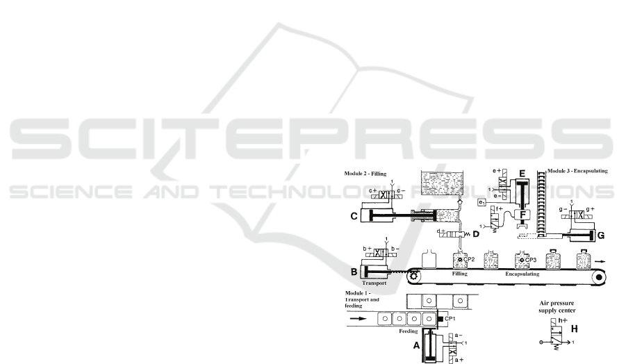
The case study corresponds to an automatic machine
of filling and encapsulating bottles (Fig. 1). This is
divided in three modules, transport and feeding,
filling and encapsulating. To increase the
productivity, is used a conveyor with several alveoli
for the bottles to allow the operation in simultaneous
of the three modules.
Figure 1: Case study plant.
The transport and feeding module is constituted by a
pneumatic cylinder (A) that is the responsible for the
bottles feeding of the conveyor and another
pneumatic cylinder (B) that executes the
step/incremental advance of the conveyor.
The filling module is composed by a volumetric
dispenser, a pneumatic cylinder (C) that actuate the
dispenser and an on/off valve (D) to open and close
the liquid supply.
SAFE CONTROLLERS DESIGN FOR HIBRID PLANTS - The Emergency Stop
173
The encapsulating module has a pneumatic cylinder
(G) to feed the cover, a pneumatic motor (F) to
screw the cover and a pneumatic cylinder (E) to
advance the cover. The cylinder (E) moves forward
until the existent cover, it retreats with this cover
during the retreat of (G), continuously it moves
forward again with rotation of the motor F to screw
the cover.
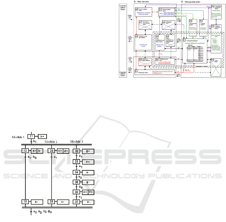
2.1 Base Controller Behaviour
Specification
Figure 2 shows the base SFC of the system
controller, corresponding only to the "Normal
production” mode. The basic sensors involved are:
two end-course-sensors for each cylinder (example:
cylinder A, sensor a0 and a1, respectively, retreated
and advanced) and a sensor of pressure e1, which
detects the point of contact/stop of the cylinder E in
any point of its course.
The valve D and the motor F don't have position
sensor because they are difficult to implement.
Figure 2: Base SFC specification controller.
On the other hand, in order to obtain the total
SFC controller, which includes all the operation
modes required for the correct operation of the
system, was used the graphic chart of GEMMA
because it allows the definition of the run and stop
machine tasks.
2.2 Total Controller Behaviour
Structure
Figure 3 shows the GEMMA graphic chart
developed for the case study presented. The
considered tasks are described to proceed:
Figure 3: GEMMA of the plant controller.
A1 – The task A1 "Stop in the initial state"
represents the task of the machine represented in the
Figure 1.
F1 – Coming of the task A1, when it occurs the
start command of the machine, it happens the change
for the task F1 "Normal production” (Filling and
automatic encapsulating) with the consequent
execution of base SFC presented in the figure 2.
A2 – When it happens the stop command of the
machine the run cycle finishes in agreement with the
condition described at the task A2 “Stop command
in the end of cycle”.
F2 – When the machine is "empty" (without
bottles) it is necessary to feed bottles progressively,
being the machine ready to begin the normal
production (task F1) when it has bottles in the
conveyor positions of the production modules 2 and
3, respectively. This operation is defined by the task
F2 “Preparation mode”.
F3 – The "Closing mode" of the task F3 allows
the reverse operation, that is, the progressive stop of
the machine with the exit of all of the bottles
(emptying of the machine).
D3 – When the encapsulating module is out of
service it can be decided to produce in any way, that
is, to perform the bottle filling in an automatic way
and posterior manual encapsulating, this is main
purpose of the task D3 "Production in any way".
D1 – In the case of a situation emergency to
occur, the task D1 “Emergency stop" is executed.
This stops all the run actions and closes the filling
valve to stop the liquid supply.
A5 – After the emergency stop (task D1), the
cleaning and the verification are necessary: this is
the purpose of the task A5 "Prepare to run after
failure“.
A6 – After the procedures of cleaning and
verification they be finished becomes necessary to
ICINCO 2009 - 6th International Conference on Informatics in Control, Automation and Robotics
174
perform the return to the initial task of the machine,
as described at the task A6 "O.P. (operative plant) in
the initial state".
F4 – For example, to the volume regulation of
the bottle liquid dispenser and adjustment of the
bottles feeder, a separate command for each
movement is required, according to the task F4
"Unordered verification mode”.
F5 – For detailed operation checks, a
semiautomatic command (only one cycle) it is
necessary to check the functioning of each module:
task F5 "Ordered verification mode".
To be possible the GEMMA evolution becomes
necessary existing transition conditions for the run
and stop operation modes, described previously.
These transition conditions will be accomplished
using GEMMA, as presented to proceed:
- To allow the progressive feeding demanded in
the preparation way (F2) and the progressive
discharge required in the closing way (F3) it will be
necessary to consider sensors that detect the bottles
presence under each one of the modules 1, 2, 3,
respectively, CP1, CP2, CP3 (Fig. 1);
- Also, it will be necessary a command panel that
supplies the transition conditions given by an
operator (Fig. 4).
Figure 4: Command panel of the system controller.
In the command panel, there is a main switch
that allows selecting the “automatic”,
“semiautomatic” and “manual” operations modes.
To the "automatic" option correspond:
- Two buttons "start" and "stop" whose action is
memorized in memory M;
- A switch HS3 to put "in service" or "out of
service" the module 3;
- A switch AA to control the bottles feeding
permission (cylinder A), to allow the emptying of
the machine.
These switches/buttons, and sensors CP1, CP2
and CP3, are the transition conditions of the tasks
A1, F1, F2, F3, A2 and D3, as shown in Figure 3.
The "semiautomatic" option corresponds to the
task F5 "Ordered verification mode", that allows
with the actuation of button (m), to check one cycle
operation of each modules, selected by the
"semiautomatic" switchc,d, or e.
The "manual" option corresponds to the tasks F4,
A5 and A6, which required a separate command
from each movement using a direct command on the
directional valves.
Finally, the AU button (Emergency stop) allows
pass to task D1 starting from all of the tasks.
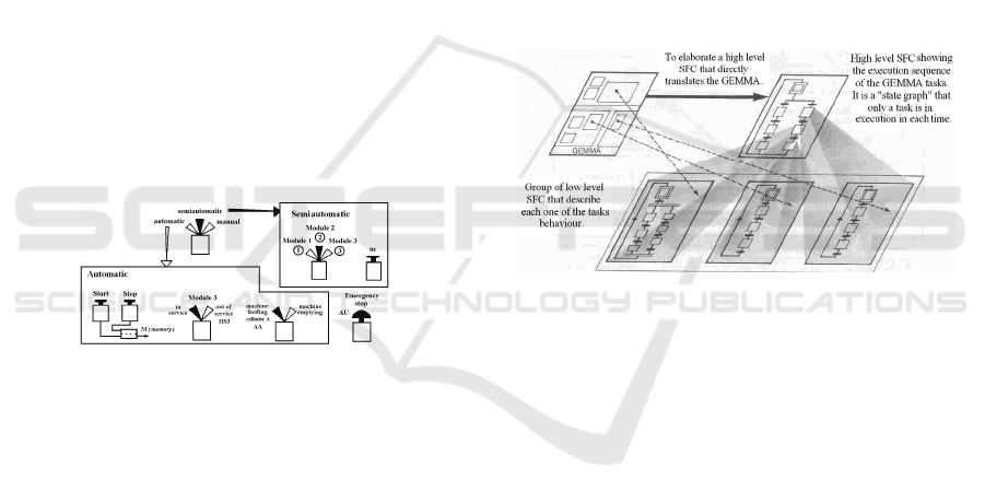
The implementation of total controller's
specification, based on GEMMA presented in figure
3, it can be realized using the following two
alternative methods:
- Multiple SFC – develop one SFC for each task;
- Single SFC – develop one SFC for all tasks.
The multiple SFC methodology is represented in
figure 5, it includes a high level SFC that translates
the GEMMA (main routine) and multiple SFC that
correspond to each task (subroutines).
On the other hand, the single SFC method
corresponds to the implementation of all GEMMA
tasks behaviour in a total SFC. This was the method
used in the presented case study (see section 4).
Figure 5: GEMMA implementation with multiple SFC.
3 EMERGENCY STOP
The emergency stop must always change the
controller task and it should be obligatorily available
in any state of the SFC controller.
The types of emergency stops are divided in two
main groups:
- Without emergency sequence - the actuation of
the emergency button stops the system/automatism
through the inhibition of the outputs and/or for stop
the evolution of SFC.
- With emergency sequence - the actuation of the
emergency button starts a particular predefined
procedure.
3.1 Without Emergency Sequence
The emergency without emergency sequence can be
performed in three alternative modes:
- Outputs inhibition;
- Evolution stop,
SAFE CONTROLLERS DESIGN FOR HIBRID PLANTS - The Emergency Stop
175
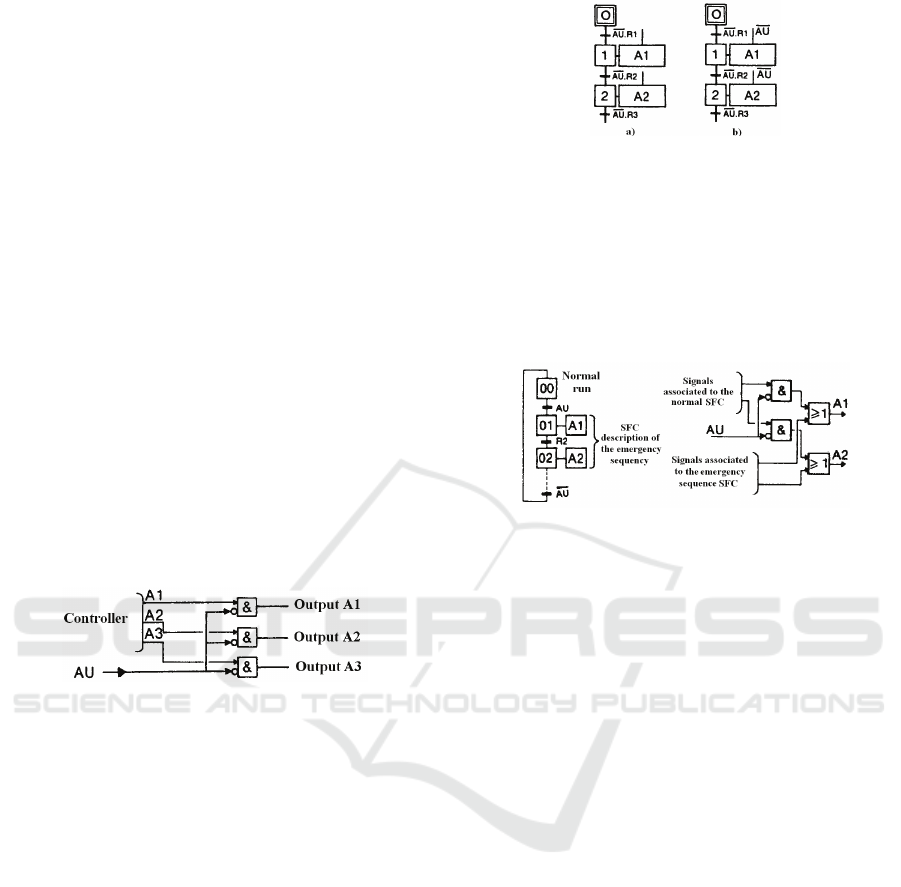
- Outputs inhibition and evolution stop.
In the case of outputs inhibition the actuation of
emergency button doesn’t stop by itself the
evolution of the SFC controller, but it inhibits the
outputs associated to their stages, as shown in the
figure 6. The outputs eventually ON (state 1) they
are turn OFF (state 0), as well as, usually the
evolution of SFC is stopped by the non fulfilment of
the receptivity’s.
This can be obtained through the insert of
inhibition functions in the interface with the machine
plant. In this case, after the occurrence of an
emergency stop, the actuators command should be
particularly well studied in agreement with the type
of expected response.
For instance, for the cylinders directional valves:
- One stable state valve (single control with
spring return), if it be demanded a cylinder return for
a given position.
- Two stable state valve (double control), if it be
demanded a stop at the end of the cylinder
movement.
- Valve with three positions (double control and
spring return), if it be demanded a cylinder stop in
the actual position.
Figure 6: Functional diagram of outputs inhibition.
In the other hand, in the case of evolution stop
the condition AU is present in all of the SFC
receptivity’s (Fig.7a). With the actuation of
emergency button AU, no receptivity can be
validated and, this way, the controller SFC cannot
steps forward. With the AU shutdown a new cycle
evolution is allowed.
It is of highlighted that in this situation, the
outputs associated to the active stages stay validated.
This way, the start movements can continue, which
be able to result in dangerous situations and/or to get
to a situation that originates a future blockade of the
SFC evolution.
Finally, also it is possible to use in simultaneous
the two described types of emergency stop without
emergency sequence, outputs inhibition and
evolution stop (Fig. 7b). This situation is the more
used in practice, when if it doesn't turn necessary the
use of an emergency sequence. Seen that has the
advantage of allowing, after the emergency button
shutdown, the pursuit of the evolution of the system
starting from the same instant in that it was stopped.
Figure 7: a - Evolution stop; b - Evolution stop and
outputs inhibition.
3.2 With Emergency Sequence
This type of emergency implies the introduction of
an emergency sequence. Through the activation of
the emergency button AU an emergency sequence
can be added to the normal run SFC (Fig. 8).
Figure 8: Introduction of an emergency sequence.
4 EMERGENCY STOP ADOPTED
SOLUTION
The emergency stop adopted for the case study
presented was obtained according the standards EN
418 and EN 60204-1.
According to the behaviour of the case study was
selected the emergency stop with emergency
sequence. The considered requirements that should
be accomplished by the emergency sequence are:
- Stop all of the movements;
- Stop the filling operation.
To obtain these procedures it was crucial the
selection of the type of the directional valves
appropriate to accomplish in simultaneous the
requirements of the emergency stop and the plant
behaviour.
The directional valves specifications used were
the type of control (single solenoid control with
spring return or double solenoid control) and number
of ways/ports.
The first security requirement referred, related
with the stop of the movements, was obtained by
stopping the air compressed supply to the directional
valves of the cylinders A, B, C, E, G and of the
motor F. For that, as shown in figure 1, the air
supply will be centralized and controlled through a
ICINCO 2009 - 6th International Conference on Informatics in Control, Automation and Robotics
176
directional valve 3/2 way normally closed with
spring return (H).
The second security requirement, related with
the stop the filling operation, was performed through
the turn OFF of the filling directional valve 2/2 way
normally closed with spring return (D).
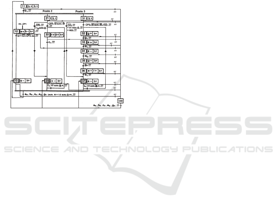
The figure 9 shows the total controller SFC
specification based on the GEMMA implementation
with the single SFC method (see section 2.2).
Figure 9: Total SFC controller specification with
emergence sequence.
All the controller specification, presented on the
previous figure, was simulated on Automation Studio
Software. The obtained results leaded to the conclusions
that all the requirements defined on the Emergency Stop
Standards, were accomplished.
Further, the specification was translated to Ladder
Diagrams according to the SFC algebraic formalization
and implemented on a Programmable Logic Controller
(PLC) adopted as the controller physical device. This part
of the developed work is not detailed on this publication.
5 CONCLUSIONS
It was presented, on a systematic way, the adopted
techniques for the emergency stop behavior
specification of automation systems.
The ways to translate the GEMMA graphical chart
to the low level specification was also presented and
discussed.
The standards (EN418, EN60204-1) related with the
stop emergency specifications were considered and
all the requirements were accomplished.
The obtained results, by simulation with Automation
Studio software, show that the adopted approach is
adequate.
Further work will be devoted, in one hand, to the
application of formal methods to verify some
important system’s behavior (taking into account the
discrete behavior of the system) and, in other hand,
the application of modeling techniques for hybrid
systems and respective tools for simulation and
formal verification.
REFERENCES
ADEPA, 1992. GEMMA (2nd Edition) – Guide d`Étude
des Modes de Marches et d`Arrêts.
Automation Studio, 2004. Famic Technologies inc.,
Automation Studio 5.0,
http://www.automationstudio.com.
Baresi L., Mauri M., Pezzè M., 2002. PLCTools: Graph
Transformation Meets PLC Design. Electronic Notes
in Theoretical Computer Science, Vol. 72, No. 2.
Elmqvist E., Mattson S., 1997. An Introduction to the
Physical Modelling Language Modelica. ESS'97.
Passau, Germany.
EN 418, 1992. Safety of machinery. Emergency stop
equipment, functional aspects. Principles for design.
European Standard.
EN 60204-1, 1997. Safety of Machinery - Electrical
Equipment of Machines - Part 1: General
Requirements-IEC 60204-1. European Standard.
Frey G., Litz L., 2000. Formal methods in PLC
programming. IEEE Conference on Systems, Man and
Cybernetics, SMC 2000, Nashville, October 8-11.
IEC 60848, 1998. Specification language GRAFCET for
sequential function chart. ed. 2.
Klein S., 2005. Fault detection of discrete event systems
using an identification approach. PhD Thesis,
University of Kaiserslautern.
Machado, J., Seabra, E. A. R., 2008. Real-Time Systems
Safety Control considering Human-Machine Interface.
ICINCO’2008, May 10-14, Funchal, Madeira,
Portugal,. 6p.
Machado, J., Seabra, E. A. R., Campos, J., Soares, F. O.,
Leão, C. P., Silva, J. C. L., 2008. Simulation and
Formal Verification of Industrial Systems Controllers.
Symp. Series in Mech.; Vol. 3, pp.461-470.
Otter M., Årzén K., Dressler I., 2005. TaskGraph - A
Modelica Library for Hierarchical Task Machines.
Modelica 2005 Proceedings.
Seabra, E. A. R., Machado, J., Silva, J. C. L., Soares, F.
O., Leão, C. P., 2007. Simulation and Formal
Verification of Real Time Systems: A Case Study.
ICINCO’2007, Angers, France; May 9-12, 6p.
Ramadge P. J. and Wonham W. M., 1987. Supervisory
control of a class of discrete event processes. SIAM J.
Control Optimization, 25(1), pp. 206-230.
Rossi O., 2004. Validation formelle de programmes
Ladder Diagram pour Automates Programmables
industriels. PhD Thesis, École Normale Supérieure de
Cachan.
SAFE CONTROLLERS DESIGN FOR HIBRID PLANTS - The Emergency Stop
177
