
THE FINS PROTOCOL FOR COMPLEX
INDUSTRIAL APPLICATTIONS
A Case Study
Júlio Costa, Nuno Carvalho
Industrial Electronics Department/ALGORITMI, University of Minho, Guimarães, Portugal
Filomena Soares
Industrial Electronics Department/ALGORITMI, University of Minho, Guimarães, Portugal
José Machado
Mechanical Engineering Department/CT2M, University of Minho, Guimarães, Portugal
Keywords: Complex Control Systems, Industrial networks, Industrial protocols, PLCs networks.
Abstract: This paper presents a comparative approach on the use of different industrial networks configurations and
industrial communication protocols. Some aspects, that may influence the right choice of the most indicated
protocol for each industrial network configuration, are discussed. It is presented a case study and two
configurations networks implementing two industrial communication protocols. The respective advantages
and disadvantages are presented. All the detailed aspects including the data exchange are presented too. The
obtained results are extrapolated for other similar industrial applications.
1 INTRODUCTION
This works appears on the context of developing and
implementing new solutions for industrial networks
implementation. This line of research is being
developed by a team from the School of Engineering
of University of Minho and involves some
departments of the School.
The first results, here presented, are the first one
obtained from an initial study that it is intended to be
more complex and exhaustive.
Industrial communications have significantly
evolved since their appearance in the 1970s. Faster
and more reliable communication protocols have
been proposed and deployed in industrial
applications (IEC 61784-2).
The necessity that the companies have to
improve their competitiveness has lead to many
developments on this field, related with more
complex industrial networks applications and with
more complex communication protocols elaboration.
This increasing of competitiveness is a constant
objective for all the companies in general and for the
Portuguese companies, in particular.
In order to facilitate the management and control
of manufacturing processes it is, currently, very
important the flexibility of the implemented
management and control systems for the
manufacturing processes. For that accomplishment,
it is necessary a fast access at the information,
means that allow a fast decisions according the
manufacturing process behavior and, more
important, the possibility of improvement of the
manufacturing systems efficiency.
With the development of the communication of
the industrial networks, with the evolution of the
industrial communication protocols and the
increasing of the exigency level - characteristic of
the manufacturing process control - the knowledge
and the know-how associated at these realities is
becoming crucial on the development and
improvement of competitiveness of the industrial
companies.
348
Costa J., Carvalho N., Soares F. and Machado J.
THE FINS PROTOCOL FOR COMPLEX INDUSTRIAL APPLICATTIONS - A Case Study.
DOI: 10.5220/0002249603480354
In Proceedings of the 6th International Conference on Informatics in Control, Automation and Robotics (ICINCO 2009), page
ISBN: 978-989-674-000-9
Copyright
c
2009 by SCITEPRESS – Science and Technology Publications, Lda. All rights reserved

In this paper it is intended to compare and
conclude about industrial network configurations
and to compare industrial communication protocols
too. Some propositions for the best communication
protocol to be applied on some industrial network
configurations are also presented.
In order to achieve the main goals proposed on
this paper, the paper is organized as follows: Section
1 used to present the challenge of the work. In
section 2 it is presented a background about
industrial networks and industrial communication
protocols. Further, section 3, it is presented a case
study that permits the application of two industrial
network configurations and, also, two industrial
communication protocols application. Section 4 is
devoted to the presentation of the developed work
followed by the Section 5, where are presented and
discussed the obtained results. Finally, section 6,
there are presented the main conclusions of this
study and some guidelines for the future work.
2 BACKGROUND
In this section it is presented a brief overview of
industrial networks and some of the most used
communication industrial protocols.
2.1 Industrial Networks
The industrial networks can be implemented
considering several types of controllers.
Among these controllers, the Programmable
Logic Controllers (PLCs) are the most used due to
their robustness when submitted to industrial
environments which are characterized by adverse
conditions (like magnetic fields, vibrations, dust,
noise, among others).
With the current increase of industrial networks,
the availability of user friendly environments and
software tools that allow a better use of the industrial
networks capabilities is also improved.
The access to different network nodes must be
fast and must allow supervising all the processes
even if they are physically independent.
An industrial network may have different
components; therefore, it implies that the connection
type between these components may be different,
leading to the need of using sub-networks. Thus, to
define some order and criteria on these links, it can
be considered a set of hierarchical levels related to a
common industrial network. These hierarchical
levels can be defined by different ways and using
different criteria. Nevertheless, the pyramid CIM
(Computer Integrated Manufacturing) (ISA-
dS95.01-1999) is a good approach for illustrating
these levels (Figure 1).
Figure 1: CIM Pyramid (ISA-dS95.01-1999).
The CIM Pyramid is divided in levels
concerning the type of application to be controlled.
The considered levels are Management, Control,
Process, and, finally, the Inputs and Outputs
variables.
The Management level is concentrated on all the
information concerning to the network. Usually, it is
used a Personal Computer (PC) in which it can be
seen all the performance of the plant using a
Supervisory Control and Data Acquisition (SCADA)
system (Pires and Oliveira, 2006).
At the Control level it is established the
connection between PCs and PLCs.
The Process level is characterized by the
controllers and PLCs for the industrial process
control.
Finally, the Inputs and Outputs level includes the
sensors and actuators devices. This is the lowest
level of the CIM Pyramid. It is also the closer level
to the plant, where the network is applied.
In the Management level, as in the Control level,
the type of network used is a Local Area Network
(LAN) (IEEE 802.1AB-2005) as for example the
Ethernet (Felser, 2005).
At the Process level other types of networks are
used. One of the most implemented is the
PROFIBUS network (PROFIBUS International, Liu
et al., 2007). Also, at this level, the Actuator/Sensor
Interface (AS-I) network may be used (Lee, 2001).
The Ethernet appears with the main goals of
reducing costs, increasing dependability, sharing the
information and the physical resources in the same
transmission environment by using a coaxial cable.
THE FINS PROTOCOL FOR COMPLEX INDUSTRIAL APPLICATTIONS - A Case Study
349

The Ethernet technology has, as physical
devices, the coaxial cables with small and large
diameter, or the plaited pair of cables.
With the Ethernet network some topologies are
possible: star, tree or ring type configurations. For
the communication between the several devices
there exist some transmission environments: the
Simplex, where the transmission is done in a
unilateral direction; the half duplex, where the
transmission is done from and to each device; and
the full duplex, where each device simultaneously
transmits and receives information.
The Profibus network has different
functionalities for its communication protocols: the
profibus Fieldbus Message Specification (FMS), the
Distributed Peripherals (DP) and the Process
Automation (PA), where the physical transmission is
done by RS485. The profibus FMS is a protocol
used on the PCs and PLCs communication, but
Ethernet network is substantially increasing on this
domain application. The DP profibus is used for the
communication between small PLCs and for the
communication between PLCs and the controllers.
With the transmission environment RS485, it can be
used a complexity until 32 devices, including the
first initial node of the connection. Usually, this
node is a small PLC. The PA profibus network is
implemented to link sensors and actuators,
connected to a master PLC that centralizes all the
relevant data to the control system.
The AS-I network is used for the lowest level of
automation systems. There are about 80 international
developer companies that use this type of network.
This is a low cost network and easy to expand.
Like Profibus, it is allowed the use of a maximum of
32 devices. The maximum allowed length is about
100 meters.
2.2 Industrial Communication
Protocols
With the increasing of the competitiveness and the
set of different PLC products existing in the market,
it is usual, in an industrial plant, to coexist different
types of PLCs. The communication between these
systems is necessary in order to accomplish all the
benefits proposed by the industrial networks.
For the communication between these physical
devices, different solutions in the set of industrial
communication protocols are used. The advantages
of universal protocols (open protocols) seem natural,
because they allow the exchanging of data and
information between different types of systems.
In this group of protocols, one of the most used
is the serial communication protocol. But there are
others, like the Synchronous Serial Interface (SSI)
and the Bi-directional Synchronous Serial Interface
(BiSS). As open protocol, the Profibus (previously
described) is also very used.
There are, also, other protocols that are restrict
and proprietary of the controllers’ manufacturers.
For instance, the Hostlink and the Factory Interface
Network Service (FINS) protocols are two examples
of a large set of these closed protocols (Kizza,
2005).
The main advantage of using closed protocols is
improving the simplicity of network implementation
and configuration. The manufacturers of these
protocols have well adapted software tools and a
very structured set of configurations that
considerably help the designers.
The main advantage of open protocols is that
they can be used and shared by different devices
from different manufacturers. Using these protocols
it is possible to exchange data and information
between several commercial devices. The
characteristics of these protocols are similar, no
matter the device manufacturer, so different
companies use them as a way to promote their own
products and also to increase the competiveness
between the device manufacturers.
In fact, if it is necessary to expand the industrial
network, adding new devices, these protocols have
real advantages when compared to the closed
protocols. In addition, they are at low cost. The main
reason to decrease the cost of these protocols is that
the devices manufacturers intend to increase the
competitiveness (Kizza, 2005).
3 CASE STUDY
The automated line production which was used in
this study is a didactic Modular Production System
(MPS) of the Mechanical Engineering Department
Automation Laboratory of University of Minho, in
Portugal. Although being didactic, this equipment is
a well achieved simulation of a real system. Its
command module is being used in real line
production systems. All the control tasks are assured
by a Programmable Logic Controllers (PLCs)
Network specially designed for the purpose (figure
2).
This system is composed by five modules,
named as follows:
Module 1 – Distribution
Module 2 – Test
ICINCO 2009 - 6th International Conference on Informatics in Control, Automation and Robotics
350
Module 3 – Processing
Module 4 – Transport
Module 5 – Separation
Figure 2: Modular Production System.
These modules have an independent control,
each one being controlled by a single PLC, all the
PLCs being controlled by a PC.
The identification of the component type is made
in the module 2. The control programming assure
that on the module 5, the components are assorted
by size, colour or material, as well as rejected
components, each one being directed to an
appropriated conveyor.
In order to obtain some results comparing the
communication protocols it was decided to
configure the control structure in two different kinds
of networks really implemented in industrial
systems.
In a first step, the PLCs corresponding to each
module were connected in a network, in a parallel
configuration, as shown in figure 3. All the
networked PLCs are at same level of control
(network N1).
Figure 3: Scheme of the implemented network (step 1 of
the study).
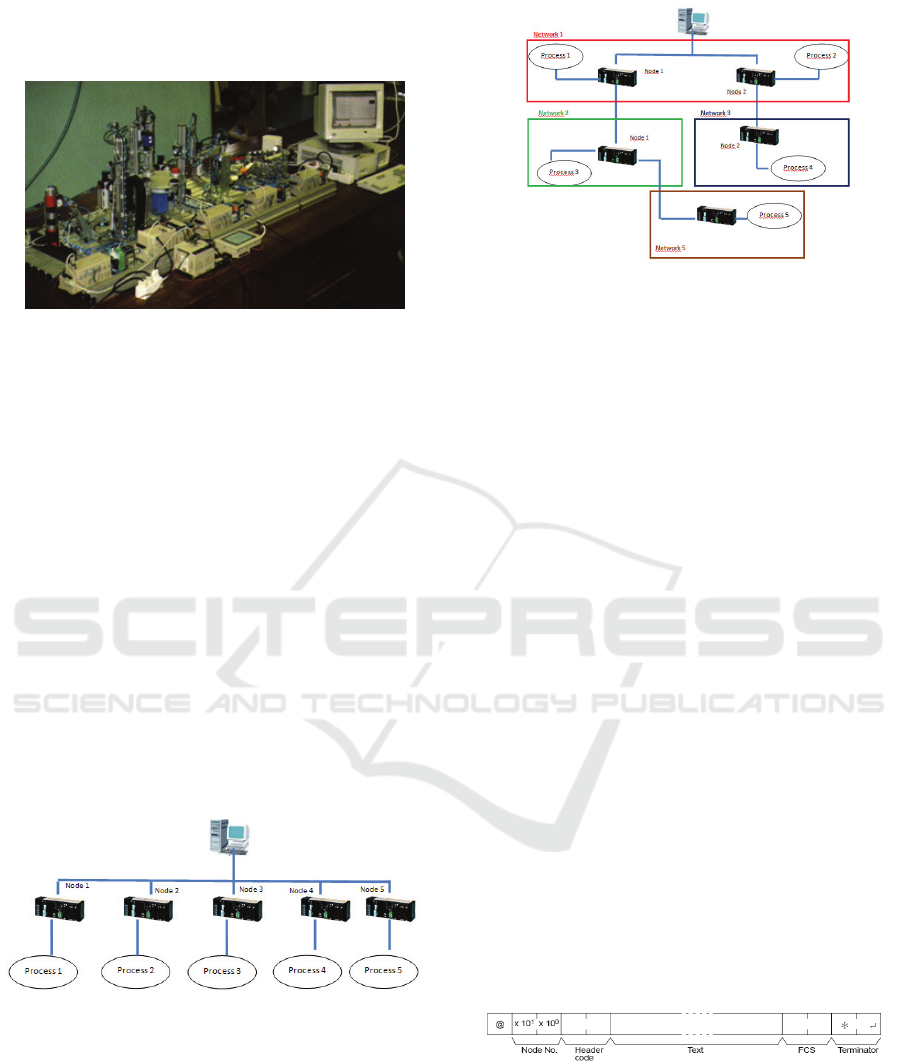
In a second step, the MPS was separated into
five independent modules, where each one
represents a sub-network, as illustrated in figure 4,
network N2.
Figure 4: Scheme of the implemented network (step 2 of
the study, with sub-networks).
The used protocols for this study were the
Hostlink and FINS protocols from OMRON
Company (www.omron.com).
On the first step approach it was used the
Hostlink protocol and on the second step approach it
was used the FINS protocol.
4 DEVELOPED WORK
Networks N1 and N2 were implemented
(www.omron.com).
In the case of network N1, Hostlink protocol is
often employed. Each PLC has a dedicate
identification number (ID). The configuration frame
includes: the PLC ID number, the definition of the
action to be performed, e.g. to read a process
variable value (counting pieces in a process line
production) or to send a command value to the
working system (switching on an actuator).
The command frame includes the following
fields (Figure 5): constant parameters definition, the
first one indicates the frame starting point and the
terminator parameter designates the ending point;
the node number is the PLC ID number for
communication; the header code and the text are the
definition of the action and the data to be exchanged
in the communication process, respectively.
Figure 5: Hostlink command frame.
The response frame to the previous command is
shown in Figure 6. The start and ending points are
identical to the command frame. The difference is in
the end code parameter definition which corresponds
to an indicator of success or error in the transmission
line established.
THE FINS PROTOCOL FOR COMPLEX INDUSTRIAL APPLICATTIONS - A Case Study
351
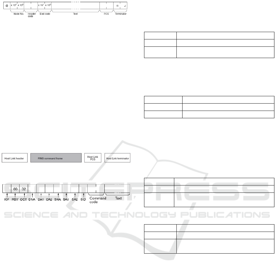
Figure 6: Hostlink response frame.
This protocol is adequate for using in a small
network with parallel PLCs configuration which can
be a constraint when working with complex control
systems. To overcome this limitation and when sub-
industrial networks are implemented (Network N2),
FINS protocol is an adequate solution.
Figure 7 shows the structure of the command
frame sent to the network to communicate to the
PLC. The frame is similar to the Hostlink protocol
but it includes the specific FINS command, the
action to be performed, the target sub-network and
the corresponding PLC, in order to establish the
communication. This frame is detailed in figure 8.
In the frame it must be defined the destination
PLC and to where (which network and PLC) the
response message should be returned.
Figure 7: FINS protocol frame.
Figure 8: Parameter specification in FINS command.
Between the FINS characteristic parameters, the
parameters DNA, DA, SNA and SA1 are particular
important, as they define the PLC communication
command target and the destination of the response
message. DNA is the destination network address,
DA1 is the destination node address and in order to
define to where the response message should be
sent, the SNA, source network address ans SA1,
source node address, must be configured.
5 RESULTS DISCUSSION
Hostlink and FINS protocols were tested and
compared in two types of industrial networks: a
simple network N1, represented in Figure 3 and a
more complex one, N2, shown in Figure 4.
First, network N1 was tested. Two values were
read from the PLC memory position Core Input
Output (CIO) starting from position number 10.
Table 1 shows the configuration of the command
frame for writing, sent by the personal computer
(PC) to the PLC, by using both protocols, Hostlink
and FINS.
Table 1: Command frame for writing.
Protocol Frame
Hostlink
@00WR000A0001000237*
FINS
@00FAF000000000102B0000A0000020001
000200*
Table 2 shows the response frame sent by the
PLC to the PC, also employing both protocols.
Table 2: PLC response frame to writing command.
Protocol Frame
Hostlink
@00WR0045*
FINS
@00FA00400000000102000040*
The test was repeated but for reading command
of two values in PLC memory CIO which are in
position 9. Tables 3 and 4 show the command for
reading sent by the PLC and the corresponding
response frame sent by the PLC.
Table 3: Command frame for reading.
Protocol Frame
Hostlink
@00RR000900034A*
FINS
@00FAF000000000101B000090000
0278*
Table 4: Answer table from PLC.
Protocol Frame
Hostlink
@00RR0000000001000243*
FINS
@00FA00400000000101000000010
00240*
Analyzing Tables 3 and 4 it is verified that the
frame lengths are different. This is due to the fact
that the configuration parameters are diverse. In this
case, network N1, Hostlink protocol is easier to
configure, the frames are shorter, being more
adequate for the application system.
A second configuration was tested, network N2,
where the MPS process is controlled by the PLC
connected to a specific sub-network.
As Hostlink protocol cannot be used in industrial
systems where sub-networks are configured, only
the FINS protocol was implemented.
Table 5 presents the command for writing sent
from the PC to the PLC positioned in a sub-network
and the corresponding PLC response command. The
command consists of writing two values starting in
position 10 of CIO memory.
ICINCO 2009 - 6th International Conference on Informatics in Control, Automation and Robotics
352

Table 5: FINS writing command/response frames.
FINS protocol Frame
Command code
@00FAF8000020101000000000001
02B0000A000002000100020A*
Response
command
@00FA00C0000200000001020000
010100000025002232*
Table 6 tests the command for reading two
positions in PLC (placed in the sub-network) CIO
memory starting from position number 10.
Table 6: FINS reading command/response frames.
FINS protocol Frame
Command code
@00FAF800002010100000000000
101B0000A0000020A*
Response
command
@00FA00C0000200000001010000
010100000025002231*
As it can be seen in Tables 3 to 6, the frames
lengths are different in all tested cases, being the
FINS frame larger than the Hostlink. FINS protocol
needs more parameters to configure the
communication. For a correct and successful data
transmission, all the FINS parameters must be
defined even if they have null value.
In the Hostlink code, the writing and reading
command frames make use of two specific
characters, namely, RR and WR, respectively.
In FINS protocol the code is implemented using
two hexadecimal values, four characters. For
example, the code 0101 is for reading and 0102 is
for writing. Both can be used to read and write in
any PLC memory position. On the contrary,
Hostlink protocol needs other commands to write in
a different memory position. Both frames signal
when the communication is successful.
Apart from having different frame lengths,
Hostlink and FINS have also different data
transmission capacity. FINS has a maximum
capacity of 1115 characters while Hostlink has a
lower capacity, 131 characters.
In summary, with FINS protocol we can access
the whole network, including the PLCs that are in a
sub-network. By using such a network it is possible
to monitor and manage the whole line production
from a working place.
For a correct use of both protocols, it is
necessary to know the network type. If two PLCs are
connected by a profibus link, the PLC slave cannot
be accessed if both master and slave PLCs are in the
same network as the PC. In profibus network, the
slave device periodically sends to the master the
memory positions, configure by the network
manager.
6 CONCLUSIONS AND FUTURE
WORK
This paper presents part of the on-going work
regarding industrial networks design for complex
systems.
An automated line production, a didactic
Modular Production System (MPS), was used as the
case-study. In spite of being didactic, this equipment
is a well achieved simulation of a real world
controlled system. All the control tasks are assured
by a Programmable Logic Controllers Network
specially designed for the purpose.
The communications protocols Hostlink and
FINS used as information coordination methods
between the PLCs and the production equipment
control system were described and tested.
Although being a proprietary communication
protocol, FINS becomes particular important due to
its simplicity, economy of time and development
costs.
In the near future, we are going to implement,
test and discuss other types of industrial protocols
using the demonstration system. An extensively
comparative study for evaluating the protocols’
performance will be carried on.
REFERENCES
IEC 61784-2: Industrial communication networks –
Profiles - Part 2: Additional fieldbus profiles for
realtime networks based on ISO/IEC 8802-3, available
at www.iec.ch
ISA-dS95.01-1999, Draft Standard, Enterprise - Control
System Integration, Part 1: Models and Terminology,
November, available at
1999www.mel.nist.gov/sc5wg1/isa95part1-d14.pdf)
Pires, P. S. M. and Oliveira, L. A. H. G., 2006, Security
aspects of SCADA and corporate network
interconnection: An overview, Proceedings of the
International Conference on Dependability of
Computer Systems (DEPCOS-RELCOMEX’06), pages
127–134, May.
IEEE 802.1AB-2005 - IEEE Standard for Local and
metropolitan area networks Station and Media Access
Control Connectivity Discovery; available at
www.ieee.org
Felser, M., 2005, Real-time Ethernet - industry
prospective, Proceedings of the IEEE, Volume 93,
Issue 6, June Page(s): 1118 – 1129
THE FINS PROTOCOL FOR COMPLEX INDUSTRIAL APPLICATTIONS - A Case Study
353

PROFIBUS International: PROFINET: Technology and
Application, System Description, Document number:
4.132, Issue April 2006, available at
www.profibus.com
Liu, J., Fang, Y., Zhang, D., 2007, PROFIBUS-DP and
HART Protocol Conversion and the Gateway
Development, Second IEEE Conference on Industrial
Electronics and Applications
Lee, K., 2001, Sensor Networking and Interface
Standardization, IEEE Instrumentation and
Measurement Technology Conference, Budapest,
Hungary, May 21-23.
Kizza, J.M., 2005, Security Threats to Computer
Networks, Computer Communications and Networks
Part II, Springer.
Spratt, Michael P.; Albrecht, Alan; Curcio, Joe; Dove,
Dan; Goody, Steve, 1994, An Overview of IEEE
802.12 Demand Priority, HP Labs Technical Reports,
available at
http://www.hpl.hp.com/techreports/94/HPL-94-17.html
ICINCO 2009 - 6th International Conference on Informatics in Control, Automation and Robotics
354
