
MODEL-DRIVEN DEVELOPMENT OF SOFTWARE
CONFIGURATION MANAGEMENT SYSTEMS
A Case Study in Model-driven Engineering
Thomas Buchmann, Alexander Dotor and Bernhard Westfechtel
Angewandte Informatik 1, Universit
¨
at Bayreuth, D-95540 Bayreuth, Germany
Keywords:
Model-driven development, Software configuration management, Software product line.
Abstract:
Software configuration management (SCM) is the discipline of controlling the evolution of large and complex
software systems. Current SCM systems are themselves large and complex. Usually, their underlying models
are hard-wired into the program code, which is written manually. In contrast, we present a modular and model-
driven approach to software configuration management which (a) reduces development effort by replacing
coding with creating executable models and (b) provides a product line supporting the configuration of an
SCM system from loosely coupled, reusable components. In addition to improving SCM support, our intent
is to use our system as a large case study for evaluating languages and tools for model-driven development.
1 INTRODUCTION
Software configuration management (SCM) is the dis-
cipline of controlling the evolution of large and com-
plex software systems. A wide variety of SCM tools
and systems has been implemented, ranging from
small tools such as RCS (Tichy, 1985) over medium-
sized systems such as CVS (Vesperman, 2006) or
Subversion (Collins-Sussman et al., 2004) to large-
scale industrial systems such as Adele ClearCase
(White, 2003). The current state of practice is charac-
terized as follows:
• SCM systems are large. For example, even the
code base of the GNU CVS project comprises
about 300,000 lines of code. CVS is still a rather
small tool compared to a commercial system for
large enterprises such as ClearCase.
• SCM systems are similar. For example, almost
all commercial and open source systems are based
on version graphs, which are used to manage the
evolution of software objects.
• The underlying models are defined only implicitly
by the program code, i.e., the model is hard-wired
into the respective system.
• SCM systems are hard to adapt to modified re-
quirements. For example, although Subversion
provides similar functionality as CVS (at least
from a bird’s eye view), the developers of Sub-
version decided to start over from scratch.
These observations have motivated us to launch a
project for developing a model-driven and modular
SCM system (MOD2-SCM (Buchmann et al., 2008)):
• The system is based on an explicit domain model
for SCM. This makes it easier to communicate
and reason about the model.
• The model is executable. Thus, development ef-
fort is reduced by generating code from the model.
• The system is designed to support a product line
for SCM systems. To this end, the executable
domain model is composed from loosely coupled
components which may be configured by defining
the features of the respective target system.
In addition to improving SCM support, our intent
is to use our system as a large case study for evalu-
ating languages and tools for model-driven develop-
ment. The research is built on the hypothesis that
model-driven development improves the software de-
velopment process. However, this cannot be simply
taken for granted. Rather, the hypothesis has to be
checked carefully, and both achievements and limita-
tions have to be identified.
309
Buchmann T., Dotor A. and Westfechtel B. (2009).
MODEL-DRIVEN DEVELOPMENT OF SOFTWARE CONFIGURATION MANAGEMENT SYSTEMS - A Case Study in Model-driven Engineering.
In Proceedings of the 4th International Conference on Software and Data Technologies, pages 309-316
DOI: 10.5220/0002250303090316
Copyright
c
SciTePress
2 APPROACH
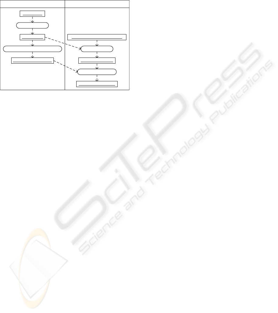
In our approach, we follow a model-driven product
line engineering process (Figure 1). In product line
Domain Engineering
Develop Executable Domain Model
Application Specific Requirements
Executable Domain Model
Feature Model
SCM Domain
Configured SCM System
Feature Configuration
Configure SCM System
Configure Features
Analyze Domain
Application Engineering
Figure 1: Engineering process.
engineering, a distinction is made between domain
and application engineering (Pohl et al., 2005). In do-
main engineering, the domain is analyzed, and soft-
ware is developed to support the respective domain.
In application engineering, a specific application, i.e.,
an instance of the product line, is created. While do-
main engineering requires a full-fledged development
process, application engineering is reduced in our ap-
proach to a configuration process. The steps of the
engineering process are described below:
Analyze Domain. The SCM domain is analyzed by
investigating and classifying SCM systems. The
result of this analysis is documented by a fea-
ture model, which is based on FODA (Feature-
Oriented Domain Analysis (Chang et al., 1990)).
The feature model describes mandatory, optional,
and alternative features of the SCM systems to be
built with the product line.
Develop Executable Domain Model. An exe-
cutable domain model is developed for the feature
model. To this end, we use Fujaba (Z
¨
undorf,
2001), an object-oriented modeling language and
CASE tool. The domain model comprises both
a structural model, defined by class diagrams,
and a behavioral model, defined by story dia-
grams (similar to UML 2.0 interaction overview
diagrams).
Configure Features. From the feature model, fea-
tures are selected for the SCM system to be built.
This results in a feature configuration.
Configure SCM System. The executable domain
model is configured automatically according to
the selected feature configuration.
3 RELATED WORK
About a decade ago, a few research projects were ded-
icated to the development of a uniform version model.
E.g., in ICE (Zeller and Snelting, 1997) version mod-
els were represented with logical expressions for ex-
pressing visibilities and constraints.
(van der Lingen and van der Hoek, 2003) pro-
poses a component-based architecture for SCM sys-
tems. Components may be viewed as variation points
offering different policies for storage, hierarchy, lock-
ing, distribution, etc.
Only a few approaches have been dedicated to
model-driven product lines of SCM systems. In Bam-
boo (Whitehead and Gordon, 2003; Whitehead et al.,
2004), version models are defined in an extended ER
data model (Containment Modeling Framework). An
SCM system is generated from a CMF model.
The PhD thesis of Kov
ˆ
se (Kov
ˆ
se, 2005) investi-
gates a product line approach to the model-driven de-
velopment of versioning systems. The user of the
product line defines a version model as a UML pro-
file; stereotypes and tagged values are used to param-
eterize the behavior of modeling elements.
Among the approaches described above, only
Bamboo and the work of Kov
ˆ
se combine model-
driven development and software product line engi-
neering. MOD2-SCM is unique with respect to be-
havioral modeling of SCM systems: In all systems
discussed above, behavior has to be programmed. In
MOD2-SCM, behavior is modeled with story dia-
grams, from which Fujaba generates executable code.
4 FEATURE MODEL
A feature is a property that is relevant to some stake-
holder and is used to capture commonalities or to dis-
tinguish among products in a product line. A feature
model consists of one or more feature diagrams. Fig-
ure 2 shows a feature diagram for a part of the SCM
domain. The diagram was created with FeaturePlugin
for Eclipse (Antkiewicz and Czarnecki, 2004). Filled
and unfilled circles represent mandatory and optional
features, respectively. An unfilled fork denotes an
exclusive-or selection, i.e., exactly one of the child
features (unfilled squares) has to be selected. Finally,
in the case of a filled fork at least one of the child fea-
tures has to selected; here, a filled square indicates a
mandatory child feature. Crosses and ticks represent
a feature configuration (Section 6).
The feature diagram distinguishes between the
Client (not considered further) and the Server. With
respect to the History, the alternatives Base (no his-
ICSOFT 2009 - 4th International Conference on Software and Data Technologies
310
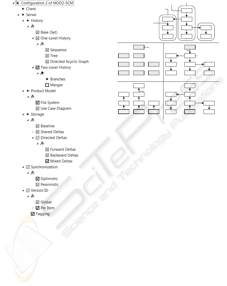
Figure 2: Feature model and feature configuration
tory), One-Level History (with subfeatures Sequence,
Tree, Directed Acyclic Graph) and Two-Level History
are provided. In the latter case, Branches are manda-
tory, and
Merges are optional. Product Model refers
to the types of items under version control, e.g.,
File
System
or Use Case Diagram. Storage is used to con-
trol the storage mechanism:
Baseline if deltas are not
used,
Shared Deltas, and Directed Deltas as shown in
Figure 3. With respect to
Synchronization, we dis-
tinguish between
Optimistic and Pessimistic. Finally,
Version ID contains a feature group for Global or Per
Item
system-defined identification, and an optional
feature
Tagging for user-defined names.
a) Version Graph
1.3.1.1
1.3.1.2
1.2.1.1
1.2.1.2
1.2.1.3
1.1
1.2
1.3
1.4
Trunk
Side Branch
Version
Successor Relationship
Baseline
b1) No Deltas
1.1
1.2.1.1 1.2
1.31.2.1.2 1.3.1.1
Reconstructed
b2) Forward Deltas
1.1
1.2.1.1 1.2
1.31.2.1.2 1.3.1.1
Forward Delta
1.41.2.1.3 1.3.1.2 1.41.2.1.3 1.3.1.2
b3) Backward Deltas
1.1
1.2.1.1 1.2
1.31.2.1.2 1.3.1.1
Backward
Delta
b4) Mixed Deltas
1.1
1.2.1.1 1.2
1.31.2.1.2 1.3.1.1
1.41.2.1.3 1.3.1.2 1.41.2.1.3 1.3.1.2
Figure 3: Logical organization of a version graph (a) and
alternative physical organizations (b)
In a product line, it is essential to provide for
orthogonal feature combination. For example, Fig-
ure 3 illustrates that the history model and the stor-
age model may be combined in an orthogonal way.
Figure 3a displays an RCS/CVS-like version graph,
which has explicit branches (two-level history). Part b
of the figure illustrates alternative physical organi-
zations (ways of storing versions). Thus, a version
graph may be stored in different ways. Conversely, a
given storage model may be combined with different
version graphs (not shown here).
5 EXECUTABLE DOMAIN
MODEL
This section presents cutouts of the executable
domain model realizing the feature model defined
above. The presentation demonstrates
• how the features are mapped into the executable
domain model,
• how the domain model supports orthogonal com-
bination of features, and
• how the behavioral model may be defined in a
high-level graphical notation.
Figure 2: Feature model and feature configuration.
tory), One-Level History (with subfeatures Sequence,
Tree, Directed Acyclic Graph) and Two-Level History
are provided. In the latter case, Branches are manda-
tory, and Merges are optional. Product Model refers
to the types of items under version control, e.g., File
System or Use Case Diagram. Storage is used to con-
trol the storage mechanism: Baseline if deltas are not
used, Shared Deltas, and Directed Deltas as shown in
Figure 3. With respect to Synchronization, we dis-
tinguish between Optimistic and Pessimistic. Finally,
Version ID contains a feature group for Global or Per
Item system-defined identification, and an optional
feature Tagging for user-defined names.
In a product line, it is essential to provide for
a) Version Graph
1.3.1.1
1.3.1.2
1.2.1.1
1.2.1.2
1.2.1.3
1.1
1.2
1.3
1.4
Trunk
Side Branch
Version
Successor Relationship
Baseline
b1) No Deltas
1.1
1.2.1.1 1.2
1.31.2.1.2 1.3.1.1
Reconstructed
b2) Forward Deltas
1.1
1.2.1.1 1.2
1.31.2.1.2 1.3.1.1
Forward Delta
1.41.2.1.3 1.3.1.2 1.41.2.1.3 1.3.1.2
b3) Backward Deltas
1.1
1.2.1.1 1.2
1.31.2.1.2 1.3.1.1
Backward
Delta
b4) Mixed Deltas
1.1
1.2.1.1 1.2
1.31.2.1.2 1.3.1.1
1.41.2.1.3 1.3.1.2 1.41.2.1.3 1.3.1.2
Figure 3: Logical organization of a version graph (a) and
alternative physical organizations (b).
orthogonal feature combination. For example, Fig-
ure 3 illustrates that the history model and the stor-
age model may be combined in an orthogonal way.
Figure 3a displays an RCS/CVS-like version graph,
which has explicit branches (two-level history). Part b
of the figure illustrates alternative physical organi-
zations (ways of storing versions). Thus, a version
graph may be stored in different ways. Conversely, a
given storage model may be combined with different
version graphs (not shown here).
5 EXECUTABLE DOMAIN
MODEL
This section presents cutouts of the executable do-
main model realizing the feature model defined
above. The presentation demonstrates
• how the features are mapped into the executable
domain model,
• how the domain model supports orthogonal com-
bination of features, and
• how the behavioral model may be defined in a
high-level graphical notation.
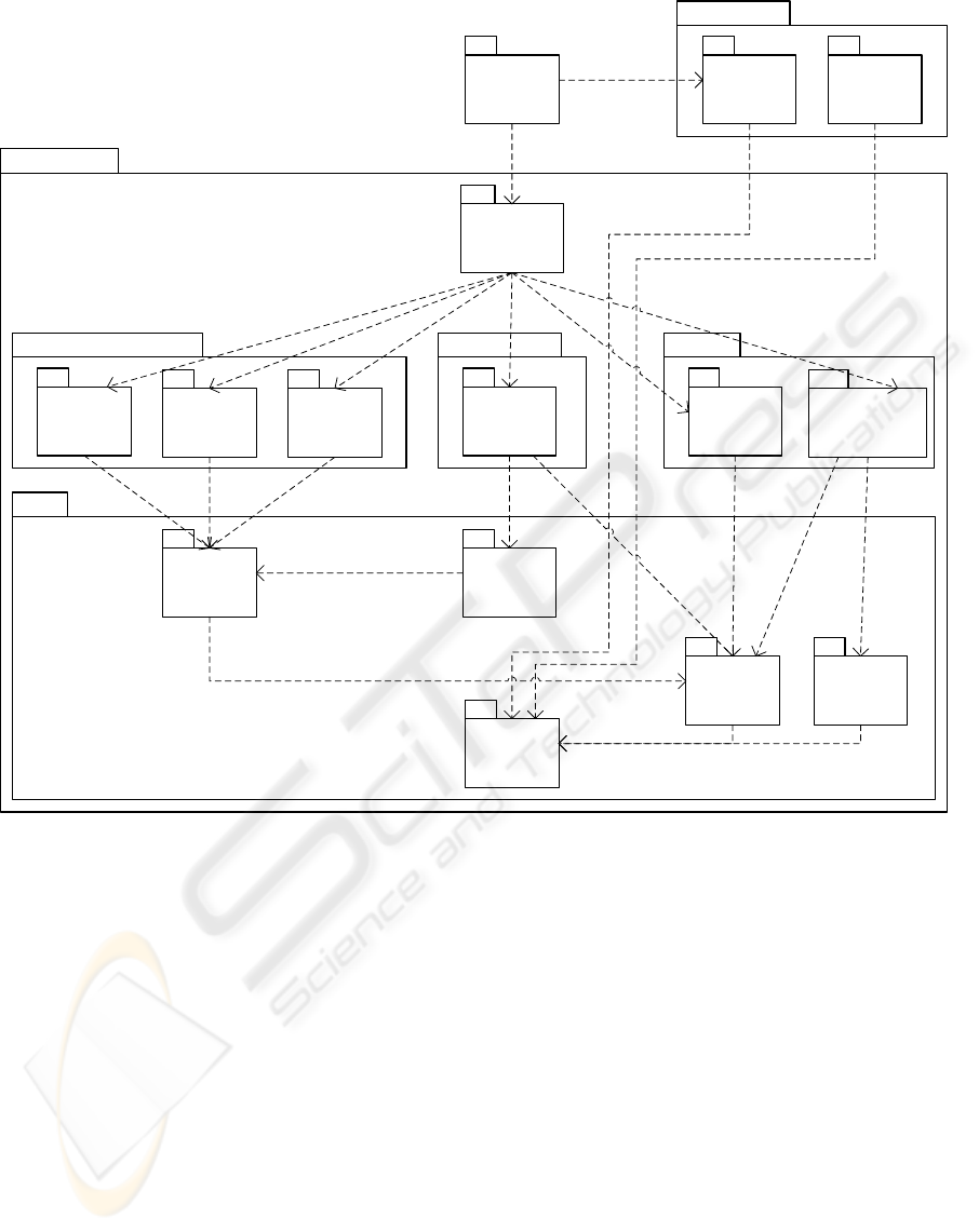
5.1 Package Diagram
Figure 4 displays the model architecture as a pack-
age diagram, using UML 2.0 notation. In addition
MODEL-DRIVEN DEVELOPMENT OF SOFTWARE CONFIGURATION MANAGEMENT SYSTEMS - A Case Study
in Model-driven Engineering
311
Product
Storage Delta
Core
Versions
Versioned
Items
Versioned Items
Base
{feature =
Base}
History {feature = Per Item}
Sequence
{feature =
Sequence}
Branches
{feature =
Branches,
Tagging}
Baseline
{feature =
Baseline}
Storage
Directed Deltas
{feature =
Directed Deltas}
Single Item
Configurable
Server
Version Model
File System
{feature =
File System}
Product Model
CVS
Workspace
Manager
Use Cases
{feature =
Use Cases}
<<import>>
<<import>> <<import>> <<import>>
<<import>>
<<import>> <<import>> <<import>>
<<import>> <<import>> <<import>> <<import>> <<import>>
<<import>>
<<import>>
<<import>>
Figure 4: Package diagram with feature annotations.
to nesting, packages are related by public imports,
which work transitively. Packages are related to the
feature model by tagged values: The tag feature is
assigned the supported feature(s) as value(s). Some
features are still missing because they have not been
implemented yet.
Version Model contains the nested package Core,
which provides basic, generic functionality on top of
which higher-level packages are built. Generic means
that the Core addresses common rather than discrimi-
nating features. Basic implies that the assumptions to
be met by higher-level packages are minimized.
Discriminating features are introduced above the
Core. History deals with version graphs and currently
supports the features Base, Sequence, and Branches.
So far, all subpackages support the identification of
versions per item, i.e., identification by global num-
bers such as e.g. in Subversion is not supported yet.
Storage provides storage of baselines and directed
deltas. Versioned Items is built on top of the Core sub-
package of the same name. Its subpackage Single Item
adds a storage to the version set (in the Core package,
versioned items are still completely independent from
the storage mechanism). Finally, Configurable Server
provides a uniform interface to the server managing
the repository.
The Version Model depends neither on the Storage
nor on the Product model. For the latter, two sample
alternatives (file systems and use case diagrams) are
provided. Finally, CVS Workspace Manager offers a
CVS-like workspace manager, relying on the file sys-
tem, branches, and mixed deltas.
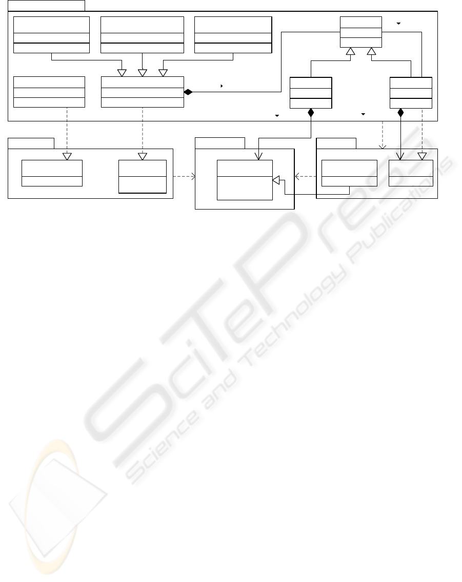
5.2 Class Diagrams
In the next step, the model architecture is refined into
a set of class diagrams. As an example, Figure 5
shows a class diagram (extending over multiple pack-
ICSOFT 2009 - 4th International Conference on Software and Data Technologies
312
Storage.DirectedDeltas
Core.Delta
Core.Storage
+duplicate()
+getItemId()
+setItemId()
«interface»
IProductItem
+compare()
«interface»
IDeltifiableItem
+apply()
«interface»
IDelta
+store()
+restore()
«interface»
IStorage
+createStorage()
«interface»
IStorageFactory
Core.Product
contains
decorates
StorageItem
+storageId
1
*
ForwardDeltaStorage
{feature = Forward Deltas}
BackwardDeltaStorage
{feature = Backward Deltas}
MixedDeltaStorage
{feature = Mixed Deltas}
DeltaStorageDeltaStorageFactory
hasNext
stores
1
*
BaselineItem
+apply()
DeltaItem
<<import>>
<<import>>
<<import>>
<<import>>
0..1
1
0..1
1
Figure 5: Class diagram for the storage model
5.2 Class Diagrams
In the next step, the model architecture is refined into
a set of class diagrams. As an example, Figure 5
shows a class diagram (extending over multiple pack-
ages) for the storage model, which relies on minimal
assumptions regarding the items to be stored. The
interface
IProductItem of package Product defines a
few methods to be supported by each class of storable
items:
duplicate() for copying an item, and get() and
set() methods for an item identifier, which is used to
uniquely identify the item to be versioned. The sub-
package
Storage of package Core introduces an in-
terface
IStorage with store() and restore() methods,
which refer to
IProductItems, and an interface for a
storage factory, offering a
createStorage() method.
Please note that
Storage is still independent of the
Delta package, which introduces an interface IDelti-
fiableItem
extending IProductItem with a compare()
method, and an interface IDelta, which is used to rep-
resent (directed) deltas between deltifiable items and
offers an
apply() method.
Implementations of storages are provided in the
subpackage
Storage of package Version Model.In
the subpackage
Storage.DirectedDeltas, the abstract
class
DeltaStorage partially implements the interface
IStorage by means of some auxiliary methods to be
called by its subclasses. A delta storage stores a set
of storage items, each of which is identified uniquely
by an externally assigned storage identifier. The ab-
stract class
StorageItem is refined into the subclasses
Baseline, which wraps a product item, and DeltaItem,
which both extends and decorates a delta. Each of
the features
Forward, Backward, and Mixed Deltas is
supported by a respective subclass of
DeltaStorage.
Finally, the package offers a factory class for creating
one of these storages.
The storage model is orthogonal to the history
model. The package
DirectedDeltas knows how to
store a new item relatively to a predecessor item.
Here, the term “predecessor” does not refer to a suc-
cessor relationship in a version graph. Rather, it
merely implies that this item must be already present
when the new item is to be stored. Furthermore, the
storage identifier must be supplied by the caller of
the
store() method. Its meaning — actually a version
identifier — is not known to the storage.
5.3 Story Diagrams
The next step consists in the realization of the meth-
ods defined in class diagrams. In Fujaba, a method
may be programmed by a story diagram, from which
executable Java code is generated. A story diagram is
an activity diagram with nodes of two kinds: A state-
ment activity consists of a fragment of Java code, al-
lowing for seamless integration of textual and graph-
ical programming. A story pattern is a communica-
tion diagram composed of objects and links; objects
may be decorated with method calls. Elements with
dashed lines represent optional parts of story patterns.
A crossed element denotes a negative application con-
dition. In addition to method calls, a story pattern
may describe structural changes: Objects and links to
Figure 5: Class diagram for the storage model.
ages) for the storage model, which relies on minimal
assumptions regarding the items to be stored. The
interface IProductItem of package Product defines a
few methods to be supported by each class of storable
items: duplicate() for copying an item, and get() and
set() methods for an item identifier, which is used to
uniquely identify the item to be versioned. The sub-
package Storage of package Core introduces an in-
terface IStorage with store() and restore() methods,
which refer to IProductItems, and an interface for a
storage factory, offering a createStorage() method.
Please note that Storage is still independent of the
Delta package, which introduces an interface IDelti-
fiableItem extending IProductItem with a compare()
method, and an interface IDelta, which is used to rep-
resent (directed) deltas between deltifiable items and
offers an apply() method.
Implementations of storages are provided in the
subpackage Storage of package Version Model. In
the subpackage Storage.DirectedDeltas, the abstract
class DeltaStorage partially implements the interface
IStorage by means of some auxiliary methods to be
called by its subclasses. A delta storage stores a set
of storage items, each of which is identified uniquely
by an externally assigned storage identifier. The ab-
stract class StorageItem is refined into the subclasses
Baseline, which wraps a product item, and DeltaItem,
which both extends and decorates a delta. Each of
the features Forward, Backward, and Mixed Deltas is
supported by a respective subclass of DeltaStorage.
Finally, the package offers a factory class for creating
one of these storages.
The storage model is orthogonal to the history
model. The package DirectedDeltas knows how to
store a new item relatively to a predecessor item.
Here, the term “predecessor” does not refer to a suc-
cessor relationship in a version graph. Rather, it
merely implies that this item must be already present
when the new item is to be stored. Furthermore, the
storage identifier must be supplied by the caller of
the store() method. Its meaning — actually a version
identifier — is not known to the storage.
5.3 Story Diagrams
The next step consists in the realization of the meth-
ods defined in class diagrams. In Fujaba, a method
may be programmed by a story diagram, from which
executable Java code is generated. A story diagram is
an activity diagram with nodes of two kinds: A state-
ment activity consists of a fragment of Java code, al-
lowing for seamless integration of textual and graph-
ical programming. A story pattern is a communica-
tion diagram composed of objects and links; objects
may be decorated with method calls. Elements with
dashed lines represent optional parts of story patterns.
A crossed element denotes a negative application con-
dition. In addition to method calls, a story pattern
may describe structural changes: Objects and links to
be created or deleted are decorated with the stereo-
type <<create>> (green) or <<destroy>> (red),
respectively. Furthermore, := and == denote attribute
assignments and equality conditions, respectively.
In the following, we present one example to il-
lustrate the style of programming with story patterns.
The store() method of class MixedDeltaStorage (Fig-
ure 6) is supplied with the item to be stored and an
externally assigned storage identifier. Please note that
MODEL-DRIVEN DEVELOPMENT OF SOFTWARE CONFIGURATION MANAGEMENT SYSTEMS - A Case Study
in Model-driven Engineering
313
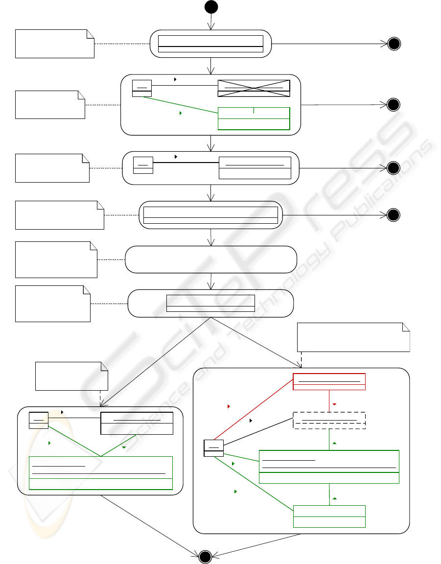
MixedDeltaStorage::store(item : IProductItem; storageID : String; context : Map) : Boolean
1 : Check if new item
is actually deltifiable
[failure]
newItem := (IDeltifiableItem) item;
String predID := (String) context.get("predID");
IDeltifiableItem predDeltaItem :=
(IDeltifiableItem) this.restore(predID, context);
[success]
5 : Retrieve storage id
of predecessor item
and restore the
predecessor
predDelta := (Delta) predItem
6 : Succeeds if the
predecessor item
is stored as a delta,
and fails otherwise
7 : Store new delta
as forward delta
[success]
this predDelta : Delta
storageID == predID
<<create>>
newDelta : Delta :=
new Delta(newItem.compare(predDeltaItem))
storageID := storageID
stores
stores
<<create>>
<<create>>
hasNext
this
<<create>>
stores
stores
<<create>>
<<create>>
hasNext
newDelta : Delta :=
new Delta(predDeltaItem.compare(newItem))
storageID := predID
<<create>>
newBaseline : Baseline
storageID := storageID
oldBaseline : Baseline
<<destroy>>
oldFirstDelta : Delta
hasNext
<<destroy>>
<<destroy>>
stores
stores
<<create>>
hasNext
[failure]
8 : Store old baseline as delta,
store new item as baseline,
and maintain reconstruction chain
true
this
stores
<<create>>
<<create>>
newBaseline : Baseline
storageID := storageID
stores
anItem : StorageItem
2 : Store first item
as baseline
true
[success]
this
stores
anItem : StorageItem
storageID == storageID
[failure]
3 : Has storageID
already been used?
false
false
[success]
predItem := this.selectPredItem(context)
[failure]
4 : Retrieve predecessor
item via context
parameter
false
[failure]
[success]
Figure 6: Story diagram for storing an item (mixed deltas).
ICSOFT 2009 - 4th International Conference on Software and Data Technologies
314

only deltifiable items can be stored; furthermore, the
storage identifier must not have been used before. If
the item is the first one to be stored, it is stored as a
baseline. Otherwise, the item is stored as a forward
delta if its predecessor is a delta, and as a backward
delta it its predecessor is a baseline.
The method store() does not assume a specific his-
tory model. Rather, it calls the method selectPred-
Item(), which retrieves the predecessor item (if any)
from the context parameter. This is a minimal as-
sumption in the case of directed deltas: The context
relative to which the new item is to be stored has to
be known. Conversely, the method for adding a new
version (not shown) does not depend on the storage
model. Rather, it merely calls the store() method of
the generic interface IStorage.
6 CONFIGURATION PROCESS
In the first step of the configuration process shown on
the right-hand side of Figure 1, the application engi-
neer describes a feature configuration for the feature
model of Section 4. Ticks and crosses in Figure 2
represent selected and disabled features, respectively.
The figure displays a CVS-like configuration (two-
level history without merge relationships, file system
as product model, mixed deltas, optimistic synchro-
nization, version identification per item, and tagging).
The second step – configuring the SCM sys-
tem – is performed automatically. When a server
is created, the selected features are used to in-
stantiate respective factories supporting these fea-
tures. For example, for the sample feature config-
uration instances of BranchedHistoryFactory (pack-
age Branches) and DeltaStorageFactory (package Di-
rectedDeltas) are created. These specific factories im-
plement generic interfaces on which the rest of the
code depends.
The server is independent from the product model
since it depends only on generic interfaces. For ex-
ample, when a version is added to the repository, an
item is passed to the server which is accessed through
generic interfaces. Therefore, the server need not be
configured with respect to the product model.
7 DISCUSSION
7.1 Executable Domain Model
The main reason for using Fujaba consists in its sup-
port for executable models. The added value com-
pared to other CASE tools is provided by story dia-
grams and their compilation into executable code. In
contrast, code generation from class diagrams is sup-
ported by numerous other CASE tools, as well, e.g.,
EMF (Steinberg et al., 2009).
More specifically, story patterns are those ele-
ments of story diagrams which significantly raise the
level of abstraction above conventional programming
languages such as Java. In contrast, the control flow
does not raise the level of abstraction. Some devel-
opers may prefer graphical over textual notation of
control flow. On the other hand, it is easy to lose ori-
entation in large story diagrams with complex control
flow. Thus, a modeler using Fujaba should keep the
principles of structured programming in mind.
7.2 Model Architecture and Design
The executable domain model has to be designed for
reuse and change. To this end, we have applied estab-
lished object-oriented design principles and patterns
to minimize the coupling of components. In addition,
we have invested significant effort in the design of a
model architecture, which defines the overall struc-
ture at a larger scale than the rather fine-grained level
on which design patterns operate. In this paper, we
have used a UML package diagram to represent the
model architecture. With the help of packages, the
coupling between architectural units cannot be con-
trolled adequately for the following reasons:
• Public imports work transitively. Thus, the dia-
gram does not tell which packages in the transitive
closure are actually used.
• A public element may always be referenced
through its full qualified name. These depen-
dencies are not reflected in the package diagram,
which cannot constrain the use of elements.
• An imported element may even be modified in
an importing namespace ((Object Management
Group, 2007), p. 143). Thus, the definition of an
element may be spread over multiple packages.
7.3 Feature Modeling and
Configuration
We have applied feature modeling to define common
and discriminating features of SCM systems. The un-
derlying concepts are simple to understand; a feature
model is an intuitive and useful means to define the
capabilities of a product line. So far, we have defined
no constraints on the combination of features (apart
from those constraints which are expressed directly
in the feature diagram itself). In fact, an essential
MODEL-DRIVEN DEVELOPMENT OF SOFTWARE CONFIGURATION MANAGEMENT SYSTEMS - A Case Study
in Model-driven Engineering
315

goal of our project consists in building a product line
for SCM systems where features may be combined as
freely as possible.
We have annotated the domain model manually
with features such that elements of the domain model
may be traced back to the feature model. These an-
notations are performed at a coarse-grained level, i.e.,
coarse-grained units such as packages or classes are
decorated with features rather than fine-grained units
such as attributes, associations, methods, parameters,
story patterns, etc. This approach keeps the multi-
variant architecture manageable.
Currently, code is generated for the complete do-
main model supporting all features. A feature con-
figuration is used to fix the parameters passed to the
method which is responsible for creating a server (see
Section 6). While this approach, which has been re-
alized on top of Fujaba, supports flexible selection of
features even at runtime, it also requires to deliver the
code for the complete product line to each individual
customer. This can be avoided by modifying the Fu-
jaba compiler such that only the code for the selected
features is generated (Buchmann and Dotor, 2009).
8 CONCLUSIONS
We presented a model-driven and modular approach
to the development of SCM systems. Furthermore,
we discussed the experiences we have gained so far
in applying model-driven product line engineering to
this application domain. Development of the product
line is still under way. Currently, the domain model
consists of 87 classes and interfaces with 283 meth-
ods. The code base comprises 19,284 lines of (almost
exclusively generated) Java code.
REFERENCES
Antkiewicz, M. and Czarnecki, K. (2004). FeaturePlugin:
Feature modeling plug-in for Eclipse. In Burke, M. G.,
editor, Proceedings of the 2004 OOPSLA Workshop
on Eclipse Technology eXchange (ETX 2004), pages
67–72, British Columbia, Canada. ACM Press.
Buchmann, T. and Dotor, A. (2009). Constraints for a fine-
grained mapping of feature models and executable do-
main models. In Proceedings of the First Interna-
tional Workshop on Model-Driven Product Line En-
gineering (MDPLE 2009), Twente, The Netherlands.
http://www.feasiple.de/workshop en.html.
Buchmann, T., Dotor, A., and Westfechtel, B. (2008).
MOD2-SCM: Experiences with co-evolving models
when designing a modular SCM system. In Proceed-
ings of the 1st International Workshop on Model Co-
Evolution and Consistency Management, Toulouse,
France.
Chang, K. C., Cohen, S. G., Hess, J. A., Novak, W. E.,
and Peterson, A. S. (1990). Feature-oriented domain
analysis (FODA) feasibility study. Technical Report
CMU/SEI-90-TR-21, Software Engineering Institute,
Carnegie Mellon University, Pittsburgh, Pennsylva-
nia.
Collins-Sussman, B., Fitzpatrick, B. W., and Pilato, C. M.
(2004). Version Control with Subversion. O’Reilly &
Associates, Sebastopol, California.
Kov
ˆ
se, J. (2005). Model-Driven Development of Version-
ing Systems. PhD thesis, University of Kaiserslautern,
Kaiserslautern, Germany.
Object Management Group (2007). OMG Unified Model-
ing Language (OMG UML), Infrastructure, V 2.1.2.
Needham, Massachusetts, formal/2007-11-04 edition.
Pohl, K., B
¨
ockle, G., and van der Linden, F. (2005). Soft-
ware Product Line Engineering: Foundations, Princi-
ples and Techniques. Springer, Berlin, Germany.
Steinberg, D., Budinsky, F., Paternostro, M., and Merks,
E. (2009). EMF Eclipse Modeling Framework. The
Eclipse Series. Addison-Wesley, Upper Saddle River,
NJ, 2nd edition.
Tichy, W. F. (1985). RCS – A system for version control.
Software: Practice and Experience, 15(7):637–654.
van der Lingen, R. and van der Hoek, A. (2003). Dissecting
configuration management policies. In (Westfechtel
and van der Hoek, 2003), pages 177–190.
Vesperman, J. (2006). Essential CVS. O’Reilly & Asso-
ciates, Sebastopol, California.
Westfechtel, B. and van der Hoek, A., editors (2003). Soft-
ware Configuration Management: ICSE Workshops
SCM 2001 and SCM 2003, LNCS 2649, Portland,
Oregon. Springer.
White, B. A. (2003). Software Configuration Management
Strategies and Rational ClearCase. Object Technol-
ogy Series. Addison-Wesley, Reading, Massachusetts.
Whitehead, E. J., Ge, G., and Pan, K. (2004). Automatic
generation of hypertext system repositories: a model
driven approach. In 15th ACM Conference on Hy-
pertext and Hypermedia, pages 205–214, Santa Cruz,
CA. ACM Press.
Whitehead, E. J. and Gordon, D. (2003). Uniform com-
parison of configuration management data models. In
(Westfechtel and van der Hoek, 2003), pages 70–85.
Zeller, A. and Snelting, G. (1997). Unified versioning
through feature logic. ACM Transactions on Software
Engineering and Methodology, 6(4):397–440.
Z
¨
undorf, A. (2001). Rigorous object oriented software de-
velopment. Technical report, University of Paderborn,
Germany.
ICSOFT 2009 - 4th International Conference on Software and Data Technologies
316
