
INDOOR WIRELESS LOCALISATION NETWORK USING A
MOBILE PHONE INTERFACE
Matthew D’Souza
Autonomous Systems Laboratory, CSIRO ICT Centre, Brisbane, Australia
Montserrat Ros
School of Electrical, Computer and Telecommunications Engineering, University of Wollongong, Wollongong, Australia
Adam Postula
School of Information Technology and Electrical Engineering, The University of Queensland, Brisbane, Australia
Keywords: Indoor Localisation, Wireless Sensor Network, Mobile Phone.
Abstract: In recent years, indoor localisation and movement tracking of people and objects has generated interest for a
variety of applications ranging from transport to health care. We present a localisation network designed to
track people in an indoor environment. The localisation network consists of static nodes placed at
predetermined locations in a building. Users carry a mobile node to track their current position. The mobile
node has onboard motion sensors to detect a person’s heading direction and motion state. A dynamic
tracking mode was used to determine a person’s position. The dynamic tracking model was implemented
using a Multi-Hypothesis Estimation algorithm. The dynamic tracking model determines the mobile node’s
position by using the mobile node’s proximity to static nodes, mobile node’s motion sensor information and
the building’s floor-plan. We found that by using a multi-hypothesis estimation algorithm, robust
localisation accuracy, could be achieved in real-time. The position resolution of the localisation network
was found to have a maximum error between 1m and 3.5m. Further work involves extensive testing the
localisation network with multiple mobile nodes and over a larger test region. Other areas involve
investigating how multiple mobile nodes placed on a user can be used to improve the estimate of the user’s
position.
1 INTRODUCTION
Tracking the position of people or objects has uses
for a wide range of applications in transport
management, agriculture and health domains. Our
paper presents a wireless localisation network that
uses inertial sensors to track a person's position in an
indoor environment. The localisation network also
used a dynamic tracking model based on a Multi-
Hypthosis Estimation algorithm. The dynamic
tracking model allowed the localisation network to
achieve robust localisation accuracy with low cost
inertial sensors and radio transceivers.
The localisation network consists of static nodes
placed at predetermined positions throughout a
building. The user carries a mobile node which
localises their position. The static nodes are used to
determine the presence of the user within a
particular region of a building. The user’s position is
determined by the dynamic tracking model. The
dynamic tracking model uses the mobile node’s
movement information (heading), proximity
information from the nearest static node and
building’s floor-plan to track the mobile node. The
user can also view their current position using a
mobile phone.
Our localisation network architecture is based on
the localisation network by Klingbeil et al (Klingbeil
and Wark, 2008). One of the disadvantages of that
Localisation Network was the use of power
consuming sensors in their mobile node, such as a
magnetometer to detect a user’s heading with respect
45
D’Souza M., Ros M. and Postula A. (2009).
INDOOR WIRELESS LOCALISATION NETWORK USING A MOBILE PHONE INTERFACE.
In Proceedings of the International Conference on Wireless Information Networks and Systems, pages 45-50
DOI: 10.5220/0002261200450050
Copyright
c
SciTePress
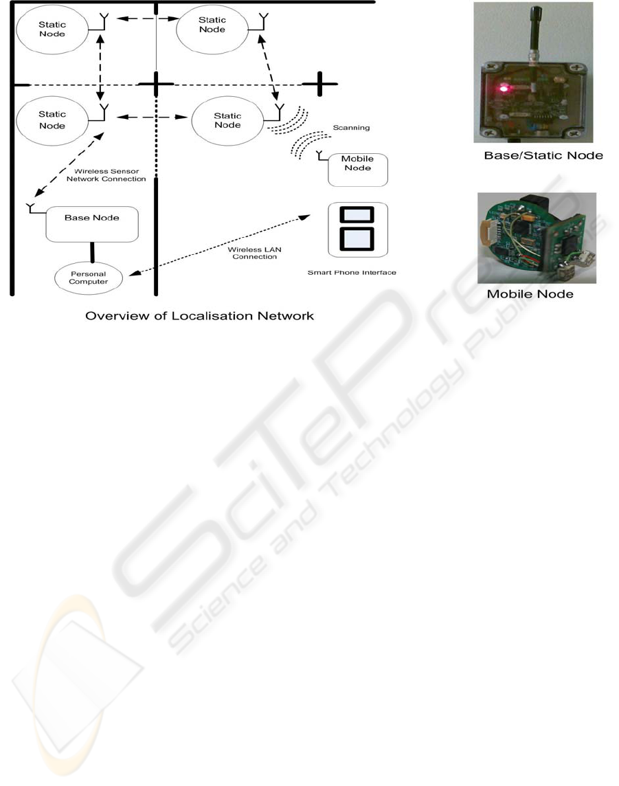
Figure 1: Localisation Network Overview.
to magnetic north. Another disadvantage was the use
of a relatively large mobile node, which was found
to be too cumbersome to attach to people.
Our localisation network uses the Fleck Nano
wireless sensor platform to implement the mobile
node and the Fleck
TM
-3 wireless platform for the
static nodes. The Fleck Nano platform was designed
to be a small, inexpensive wireless sensor with
minimal computation resources that can be used to
complement other sensor platforms.
The contributions of this paper can be
summarised as:
• Implementation of a localisation network for
position tracking.
• Experimental use of small, unobtrusive,
wireless sensors for position and motion
monitoring.
• Use of a Multi-Hypthesis Estimation based
dynamic position tracking model.
• Development of a mobile phone user interface.
This paper is organized into 6 sections. Section 2
presents a review of related work. Section 3
discusses the implementation of the localisation
network. Section 4 presents the dynamic position
tracking model. Section 5 discusses the testing
conducted. Conclusions and futher areas of
investigation are discussed in Section 6.
2 RELATED WORK
Different types of wireless technologies, such as
GPS have been investigated for outdoor and indoor
location systems. Unfortunately, GPS is not suitable
for indoor use and this has led to research into the
use of other wireless technologies including UWB
(Schwarz et al., 2005), ultrasonic and GSM (Otsason
et al., 2005) platforms.
Lamarca et al (Hightower et al., 2006, LaMarca
et al., 2005) describes the Placelab geophysical
location system which localises users in an urban
environment. The Placelab system uses the Received
Signal Strength Indicators (RSSI) from Wireless
LAN hotspots and GSM broadcast towers to
determine a user's position. The Placelab software
uses a database of known wireless LAN hotspots
and GSM broadcast towers. The Placelab software
can be used with a PDA or laptop with wireless
LAN or GSM connectivity. Localisation accuracy is
stated as being less then GPS, with 20-25m using
wireless LAN and 100 to 150m for GSM broadcast
towers.
A classical case of using wireless beacons for
navigation is the Active Badge project, presented in
(Want et al., 1992). The Active Badge project
achieved a 5-10m accuracy using infrared. The
main drawback of this platform is that it required
line of sight between beacons.
WINSYS 2009 - International Conference on Wireless Information Networks and Systems
46
An extension of the Active Badge project was
the ORL location system by (Ward et al., 1997)
which developed a prototype network of ultrasonic
beacons to perform real-time tracking of tagged
mobile devices in an office environment. Other
ultrasonic location systems such as the Cricket Mote
(Priyantha et al., 2000).
3 LOCALISATION NETWORK
An overview of the localisation network, seen in
Figure 1, consisted of static nodes placed at
predetermined positions on a building level. The
mobile node is carried by a user, which localises
their current position. The static nodes are used to
determine a mobile node’s regional position and
general heading. The base node displays the current
position of the mobile nodes. This section describes
an overview of the network topology and also
describes the implementation of the localisation
network.
3.1 Base Node
The base node was implemented using the Fleck
TM
-3
wireless sensor platform (Corke et al., 2007). This
platform has been used for a variety of wireless
sensor applications particularly for environmental
monitoring (Corke et al., 2007). The Fleck
TM
-3 uses
the Atmega128 micro-controller along with the
Nordic NRF905 radio transceiver operating in the
ISM band. The Fleck
TM
-3 also incorporates a real-
time clock chip to reduce micro-controller overheads
for timing operations.
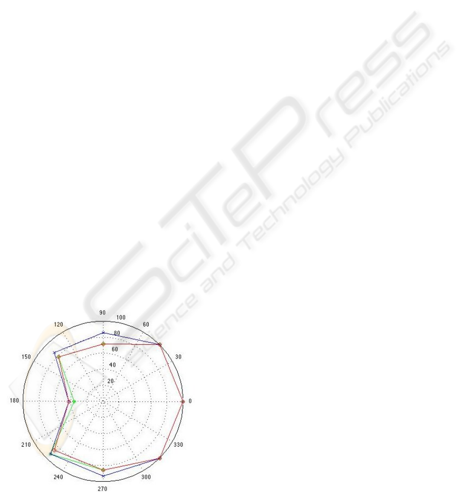
Figure 2: Fleck Nano Packet Delivery Ratio (%) vs
Antenna Angular Direction.
An operating system called Fleck Operating
System (FOS) was used to provide a priority-based,
non-preemptive (cooperative) threading
environment. This has the advantage of a simple
concurrent programming model. All application
software on the static and base nodes ran on top of
FOS. The static node can be seen in Figure 1.
The base node is connected via a serial
connection to a Personal Computer (PC). The PC
implements the dynamic position tracking model
used to track the location of the mobile node. The
model displays a building floor-plan with the current
position of the mobile node.
3.2 Static Node
The Static Node was also implemented using the
Fleck
TM
-3 platform. The primary function of the
static node is to compute the packet delivery ratio of
nearby mobile nodes. The packet deliver ratio is
calculated by counting the number of messages
received from the mobile node. Once the mobile
node’s current packet delivery ratio has been
calculated, it forwards this and the mobile node’s
accelerometer data to the base node.
The static nodes are connected to the base node
via a wireless multi-hop network. The wireless
multi-hop network employs the Link Quality Multi-
Hop Network Routing communication protocol
(Stephen et al., 2008). The advantage of using a
wireless multi-hop network is that static nodes only
have to be within range of at least one other static
node. This allows static and base nodes to be easily
deployed in an indoor environment. Each static node
will relay a received message to either the base
station or the nearest static node neighbour.
3.3 Mobile Node
The Fleck Nano platform was used to implement the
mobile node. It consists of a Nordic 915Mhz RF
transceiver, onboard microcontroller, a 3-axis
accelerometer and 2-axis gyroscope for motion
detection. Figure 1 shows the Fleck Nano as a
mobile node. It uses a coin cell battery as a power
source. The dimensions are 25mm x 20mm. The
Fleck Nano’s small physical profile and onboard
accelerometer is advantageous for our application
because it is unobtrusive. The range of the Fleck
Nano’s RF transceiver’s range was limited to
approximately 7m by setting the lowest transmission
power level. This allows improves the localisation
resolution of the mobile node.
INDOOR WIRELESS LOCALISATION NETWORK USING A MOBILE PHONE INTERFACE
47
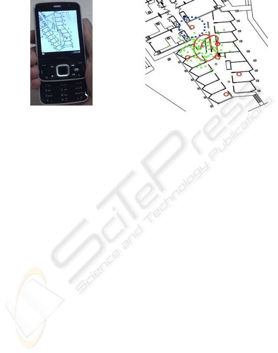
Figure 3: Mobile Phone User Interface Application.
The packet delivery ratio was used to estimate
the link quality of the RF Channel because the Fleck
Nano’s Nordic RF transceiver does not detect the
RSSI of intercepted transmissions. Packet delivery
ratio is a measure of many packets was received
over a wireless link. The directional sensitivity of
the Fleck Nano was measured in terms of antenna
angular direction and packet delivery ratio. Figure 2
shows the angular direction sensitivity of the Fleck
Nano’s antenna, which was tested by rotating the
Fleck Nano away from a static node. The Fleck
Nano has a high packet delivery ratio in its forward
direction (0 degrees) but a poor packet delivery ratio
in its reverse direction (180 degrees).
The two inertial sensors integrated with the
monitoring node were an accelerometer and a
gyroscope. Accelerometers measure the acceleration
force caused by walking. The accelerometer used on
the mobile node was the SCA3100 3-axis
accelerometer from VTI Technologies (VTI
Technologies). The SCA3100 has a sensitivity of
20mg and a maximum range of ±2g. The dynamic
position tracking model used the accelerometer
information to determine if the mobile node was
moving.
The gyroscope was used to determine the
heading of the user by measuring how much the user
has turned horizontally. Gyroscopes measure the
angular velocity of a moving object. The angular
velocity can be used to measure the directional
heading the object is moving in. The 2-axis
gyroscope module used was the IDG-300
(InvenSense) from Invensense. The IDG-300 has a
maximum range of ±500°/s.
Figure 4: Graphical User Display showing the Floor-Plan.
Red Circles represent Static Nodes, Green Dots represent
position estimates, Blue Dots high light nearest Static Node and
Red line illustrates path of Mobile Node.
3.3.1 Mobile Phone User Interface
A Nokia N96 Mobile Phone can be used to view the
user’s current position. The Mobile Phone
communicates via a Wireless LAN connection to the
base node’s PC as seen in Figure 1. The mobile
phone interface is shown in Figure 3. The mobile
phone application dynamically updates the display
using the coordinates calculated by the mobile node.
The application was implemented using Python
scripting.
4 DYNAMIC POSITION
TRACKING MODEL
The Dynamic Position Tracking model used a Monte
Carlo Multi-hypothesis estimation algorithm or
Particle Filtering. The model runs on a PC and
positions are updated every time a packet is received
from a mobile node. Figure 4 shows the graphical
user interface, which displays the current position of
a mobile node on the building’s floor-plan. The
model computes the mobile node’s position by
combining three key pieces of information:
• Proximity of static nodes determined by the
mobile node’s packet delivery ratio.
• Motion and heading information derived from
the onboard inertial sensors.
• Position of the mobile node on the floor-plan.
WINSYS 2009 - International Conference on Wireless Information Networks and Systems
48
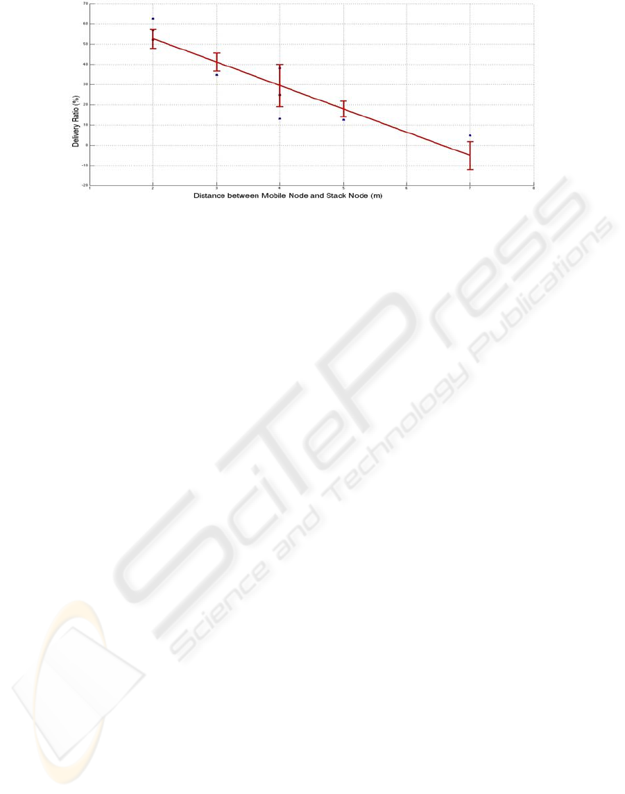
Figure 5: Separation Distance between Mobile and Static Nodes (m) vs Packet Delivery Ratio (%).
As shown in Figure 4, each green dot or particle
represents a random estimate of the mobile node’s
position. The red circles represent the static nodes.
The blue dots highlight the static node within range
of the mobile node. The mobile node’s path is
shown by the red line. The dynamic tracking model
uses the static-mobile node proximity and the mobile
node’s motion information (acceleration movement
and angular heading) to estimate the next position of
each particle (green dot). The position of the mobile
node is computed by averaging the coordinates of
the particles’ positions.
4.1 Proximity Estimation
The proximity of the mobile node to static nodes is
determined by the packet delivery ratio. Figure 5
shows the linear relation between the packet delivery
ratio and the separation distance between the static
node and sequence number. The separation distance
between the static and mobile node is used by the
dynamic tracking model to estimate a region where
the mobile node is likely to be situated.
4.2 Heading Estimation
The packet delivery ratio is also used to estimate the
heading of the mobile node. Figure 2 shows the
relation between the packet delivery ratio and the
mobile node’s antenna angular direction. The
mobile node’s onboard motion accelerometer and
gyroscope sensors are also used to determine it’s
heading. The acceleration sensor is used to
determine if the mobile node is moving and the
gyroscope is used to estimate the direction the user
has turned. The gyroscope can be used to detect
sudden changes in heading that cannot be detected
using the packet delivery ratio and antenna angular
direction relation.
4.3 Floor-Plan Map
The floor-plan map was used by the dynamic
tracking model to ensure that the mobile node’s
estimated position was valid. Validity is determined
by checking if the mobile node has to transverse
through a wall or barrier, in-order to move to its
predicted position. If this is found to be the case,
then the dynamic tracking model will then re-
estimate the mobile node’s position until it
determines that the node’s position is in a valid
location.
5 EVALUATION
Initial testing of the localisation network involved
placing static nodes in the level of a building and
having a user walk around while carrying a mobile
node. Testing was also performed using a robot that
moved at a constant velocity. Initial test showed that
the static nodes should be placed 5m apart provide
the most optimal coverage for the mobile nodes’
packet delivery ratio to be reliably estimated and for
the mobile node to relay its onboard motion data to
the base node via the static nodes. The position
resolution of the localisation network was found to
have a maximum error between 1m and 3.5m.
6 CONCLUSIONS AND FURTHER
WORK
In this paper we presented a localisation network
that tracks people in an indoor environment. The
localisation network consisted of static nodes placed
at known positions in a building. Users carry a
mobile node to track their current position. The
INDOOR WIRELESS LOCALISATION NETWORK USING A MOBILE PHONE INTERFACE
49

static nodes communicated with a base node that
was connected to a PC. The dynamic tracking
model, implemented on the PC, determined a user’s
position based on a Multi-Hypothesis Estimation
algorithm.
The base and static nodes were implemented
using the Fleck
TM
-3 platform. Our localisation
network uses the Fleck Nano platform for mobile
inertial sensing. The Fleck Nano platform is ideal for
our purposes because it has an onboard integrated
microcontroller and wireless transceiver, an
accelerometer for inertial sensing and also has a
small form factor. The user was also able to use a
mobile phone to view their current position. The
mobile phone was connected via a WLAN link to
the base node’s PC.
We also developed a dynamic position tracking
model for improving the localisation tracking of the
mobile node. The model used a Monte Carlo Multi-
hypothesis estimation algorithm. The model
determines the mobile node’s position by combining
the mobile node’s proximity to static nodes, heading
from onboard gyroscope and antenna angular
position and the building’s floor-plan. We found that
by using multi-hypothesis estimation we could
achieve robust localisation accuracy, in realtime.
The position resolution of the localisation network
was found to have a maximum error between 1m
and 3.5m.
Further work involves extensive testing the
localisation network with multiple mobile nodes and
over a larger test region. Other areas of investigation
involve looking at how multiple mobile nodes
placed on a person, can be used to improve the
estimate of the person’s position. We will also
investigate the use of the motion sensitive mobile
phones for estimating a person’s position.
ACKNOWLEDGEMENTS
The authors acknowledge the support provided to
this project by the Urban Interfaces Project,
Australasian CRC for Interaction Design (ACID).
REFERENCES
Corke, P., Valencia, P., Sikka, P., Wark, T. & Overs, L.
(2007) Long-duration solar-powered wireless sensor
networks. Proceedings of the 4th workshop on
Embedded networked sensors. Cork, Ireland, ACM.
Hightower, J., LaMarca, A. & Smith, I. E. (2006) Practical
Lessons from Place Lab. Pervasive Computing, IEEE,
5, 32-39.
InvenSense IDG-300 Integrated Dual-Axis Gyroscope,
2009,
http://www.invensense.com/products/idg_300.html.
Klingbeil, L. & Wark, T. (2008) A Wireless Sensor
Network for Real-Time Indoor Localisation and
Motion Monitoring. Proceedings of the 7th
international conference on Information processing in
sensor networks. IEEE Computer Society.
LaMarca, A., Chawathe, Y., Consolvo, S., Hightower, J.,
Smith, I., Scott, J., Sohn, T., Howard, J., Hughes, J.,
Potter, F., Tabert, J., Powledge, P., Borriello, G. &
Schilit, B. (2005) Place Lab: device positioning using
radio beacons in the wild. Pervasive Computing. Third
International Conference, PERVASIVE 2005.
Proceedings (Lecture Notes in Computer Science Vol.
3468). Springer-Verlag. 2005, 116-33.
Otsason, V., Varshavsky, A., LaMarca, A. & de Lara, E.
(2005) Accurate GSM indoor localization. UbiComp
2005: Ubiquitous Computing 7th International
Conference, UbiComp 2005. Proceedings (Lecture
Notes in Computer Science Vol. 3660) . Springer-
Verlag. 2005, 141-58.
Priyantha, N. B., Chakraborty, A. & Balakrishnan, H.
(2000) The Cricket location-support system. MobiCom
2000. Proceedings of the Sixth Annual International
Conference on Mobile Computing and Networking.
ACM. 2000, 32-43.
Schwarz, V., Huber, A. & Tuchler, M. (2005) Accuracy of
a commercial UWB 3D location/tracking system and
its impact on LT application scenarios.
Stephen, R., Wen, H. & Peter, C. (2008) An empirical
study of data collection protocols for wireless sensor
networks. Proceedings of the workshop on Real-world
wireless sensor networks. Glasgow, Scotland, ACM.
VTI Technologies Data Sheet: SCA3100-D04 3-Axis High
Performance Accelerometer With Digital SPI
Interface, 2009, http://www.vti.fi/midcom-
serveattachmentguid-
15dea0383c2711ddbf604fe1cb479fb09fb0/sca3100-
d04_accelerometer_datasheet_82_688_00_d.pdf.
Want, R., Hopper, A., Falcao, V. & Gibbons, J. (1992)
The active badge location system. ACM Transactions
on Information Systems, 10, 91-102.
Ward, A., Jones, A. & Hopper, A. (1997) A new location
technique for the active office. Personal
Communications, IEEE [see also IEEE Wireless
Communications], 4, 42-47.
WINSYS 2009 - International Conference on Wireless Information Networks and Systems
50
